Key Takeaways
- Core idea: A steady flow process is an open-system control-volume process where mass and energy cross the boundary but do not accumulate inside over time.
- Engineering use: It is the main model behind turbines, compressors, pumps, nozzles, diffusers, throttling valves, boilers, condensers, and heat exchangers.
- What controls it: The result depends on mass flow rate, enthalpy change, heat transfer, shaft work, velocity change, elevation change, and justified assumptions.
- Practical check: Start with the full energy balance, then remove heat, work, kinetic energy, or potential energy terms only when the device physics support it.
Table of Contents
Introduction
A steady flow process is a thermodynamic process where fluid moves through a control volume while the properties inside the control volume remain constant with time. Mass and energy can cross the boundary, but there is no net buildup of mass or energy during steady operation, making the model essential for open-system devices.
Steady Flow Process Diagram
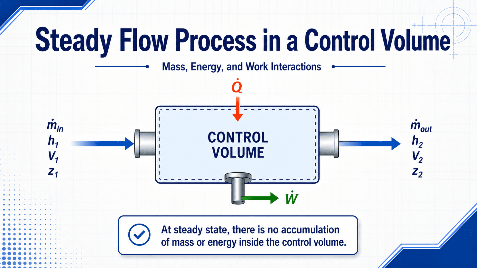
The key idea is the fixed control volume: fluid enters, fluid leaves, and heat or work may cross the boundary, but the control volume itself is not filling, emptying, warming up, or cooling down with time.
What Is a Steady Flow Process?
A steady flow process is an open-system process where the state of the control volume does not change with time. Pressure, temperature, density, velocity, and energy inside the device may vary from one location to another, but at any fixed location they remain constant during steady operation.
This is different from a closed-system process, where a fixed mass is followed as it expands, compresses, heats, or cools. In a steady flow process, the engineer fixes a region in space around the device and tracks the mass and energy entering and leaving that region.
| Term | Meaning in a steady flow process |
|---|---|
| Steady | Properties at a fixed location do not change with time during the analysis period. |
| Flow | Mass crosses the control volume boundary through one or more inlets and outlets. |
| Process | Energy interactions occur through flowing mass, heat transfer, shaft work, kinetic energy, and potential energy. |
| Control volume | A fixed region in space used to analyze an open system such as a turbine, compressor, nozzle, or heat exchanger. |
Steady Flow vs Steady-State Steady-Flow
Many thermodynamics texts use steady flow process and steady-state steady-flow process closely together. The important condition is that the control volume has no net accumulation of mass or energy with time. The flow can still change from inlet to outlet; it just does not change with time at a fixed point during steady operation.
Steady Flow Process vs Closed-System Process
A steady flow process is usually analyzed as an open-system control-volume problem because mass crosses the system boundary. A closed-system process follows a fixed mass, so no mass crosses the boundary.
| Steady flow process | Closed-system process |
|---|---|
| Mass crosses the control volume boundary. | The same fixed mass is followed through the process. |
| Usually uses enthalpy because flow work matters. | Often uses internal energy for non-flow energy storage. |
| Common for turbines, compressors, pumps, nozzles, and heat exchangers. | Common for piston-cylinder devices, rigid tanks, and closed containers. |
| Steady operation removes mass and energy accumulation terms. | Energy storage in the system may change during the process. |
How Steady Flow Works in a Control Volume
Steady flow analysis begins by drawing a control volume around the equipment. The control surface cuts through the inlet and outlet flow areas and may also be crossed by heat transfer, shaft work, electrical work, or other energy interactions.
Mass balance
For a simple one-inlet, one-outlet steady flow device, the mass flow rate entering equals the mass flow rate leaving. More complex devices may have multiple inlets and outlets, but the same idea holds: total mass flow in equals total mass flow out when there is no accumulation.
Energy balance
Energy can enter or leave as heat, work, enthalpy carried by mass, kinetic energy, and potential energy. Under steady operation, the energy stored inside the control volume is constant, so the incoming and outgoing rates must balance after accounting for heat and work.
Multiple inlets and outlets
For multiple inlets and outlets, the same balance is applied using sums of \(\dot{m}h\), \(\dot{m}V^2/2\), and \(\dot{m}gz\) terms for each stream. Mixing chambers, heat exchangers, and separators often require this more general control-volume view.
In real thermodynamics problems, \(h_1\) and \(h_2\) usually come from steam tables, refrigerant tables, ideal-gas property tables, equations of state, or software after pressure, temperature, quality, or composition are known.
Steady-Flow Energy Equation
The steady-flow energy equation is the First Law of Thermodynamics written for a control volume at steady state. The rate form is useful when calculating power or heat-transfer rate:
The per-unit-mass form is useful when working with property tables in kJ/kg:
In compact form, the equation says that the net heat added minus the net work produced equals the change in flow energy, kinetic energy, and potential energy of the fluid stream.
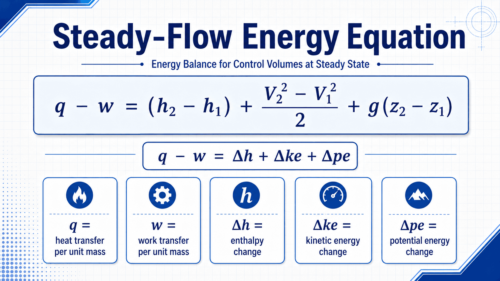
- \(q\) Heat transfer per unit mass, commonly in kJ/kg. Positive when heat enters the control volume using the sign convention shown here.
- \(w\) Work transfer per unit mass, commonly in kJ/kg. Positive here when work is produced by the control volume.
- \(h\) Specific enthalpy, commonly in kJ/kg. It includes internal energy plus flow work.
- \(V^2/2\) Kinetic energy per unit mass. Use consistent units and convert J/kg to kJ/kg when combining it with tabulated enthalpy values.
- \(gz\) Potential energy per unit mass. Often small in compact equipment, but important in elevation-sensitive flow systems.
Flowing fluid must be pushed into and out of a control volume. Enthalpy is useful because it combines internal energy and flow work into one property, which is why \(h\), not just \(u\), appears in most steady-flow device equations.
Some textbooks use work input as positive or write the equation with all terms moved to the other side. The physics is the same as long as the chosen heat and work sign convention is used consistently from start to finish.
Common Steady Flow Devices
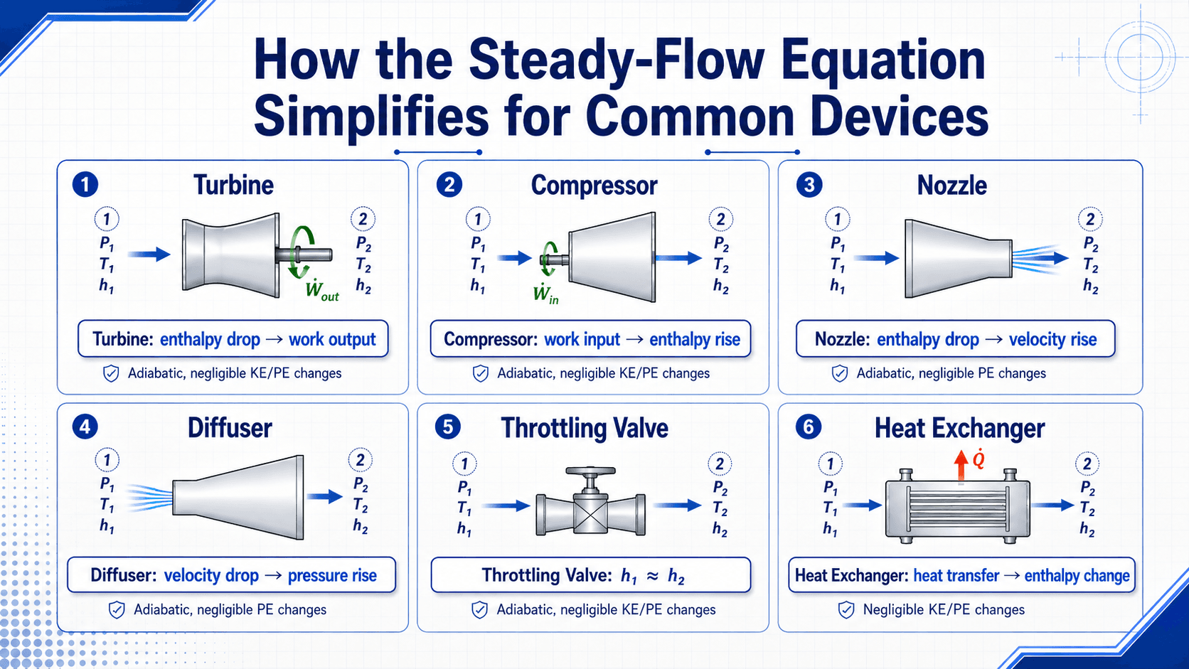
The most common steady flow devices are turbines, compressors, pumps, nozzles, diffusers, throttling valves, boilers, condensers, and heat exchangers. Each device keeps a different part of the energy equation because each one is designed to do a different job.
| Device | Common simplification | Engineering meaning |
|---|---|---|
| Turbine | Often adiabatic, negligible kinetic and potential energy changes | Fluid enthalpy decreases as shaft work is produced. |
| Compressor | Often adiabatic, negligible kinetic and potential energy changes | Shaft work input raises the fluid enthalpy and usually pressure. |
| Pump | Liquid flow, small temperature change, negligible kinetic and potential energy changes | Work input mostly increases pressure energy in the liquid. |
| Nozzle | Adiabatic, no shaft work, often negligible potential energy change | Enthalpy drop is converted into higher velocity. |
| Diffuser | Adiabatic, no shaft work, often negligible potential energy change | Velocity decreases and pressure typically rises. |
| Throttling valve | Adiabatic, no shaft work, negligible kinetic and potential energy changes | Enthalpy is approximately constant, so \(h_1 \approx h_2\). Temperature may still change for real gases and refrigerants. |
| Heat exchanger | No shaft work, usually negligible kinetic and potential energy changes | Heat transfer between streams changes enthalpy. |
Pump approximation for incompressible liquids
For liquid pumps, a useful approximation is based on specific volume and pressure rise:
This approximation is most useful for liquids because their specific volume changes very little with pressure compared with gases.
Heat exchanger two-stream balance
For an insulated heat exchanger with negligible external heat loss, the heat lost by the hot stream is approximately the heat gained by the cold stream:
Key Assumptions That Control the Result
A steady flow process is only as accurate as its assumptions. The largest mistakes usually come from deleting terms without checking whether the device behavior actually supports that simplification.
| Factor | Why it matters | Engineering implication |
|---|---|---|
| Steady-state operation | The mass and energy stored inside the control volume must remain constant with time. | Startup, shutdown, filling, blowdown, and rapidly changing load usually require unsteady analysis. |
| Heat transfer | Some devices are well insulated, while others are designed specifically to transfer heat. | Assuming adiabatic behavior is reasonable for some turbines and nozzles, but not for boilers, condensers, or heat exchangers. |
| Shaft work | Turbines, compressors, and pumps exchange mechanical work through a shaft. | Ignoring work in rotating equipment usually produces a physically wrong energy balance. |
| Kinetic energy change | Velocity changes can dominate nozzles, diffusers, jets, and high-speed gas flows. | Neglecting \(V^2/2\) is acceptable in many heat exchangers but dangerous in nozzle and diffuser problems. |
| Potential energy change | Elevation change is often small in compact machinery but important in tall piping systems or hydropower contexts. | Use judgment before dropping the \(gz\) term when vertical elevation differences are significant. |
If velocity changes from 50 m/s to 150 m/s, the kinetic energy change is \((150^2 – 50^2)/2 = 10{,}000 \, \text{J/kg} = 10 \, \text{kJ/kg}\). That conversion matters because steam tables and refrigerant tables usually list enthalpy in kJ/kg.
Steady Flow Process Examples
Steady flow examples are best understood by matching the device to the dominant energy conversion. A turbine converts enthalpy drop into work output, a nozzle converts enthalpy drop into velocity increase, and a throttling valve is commonly modeled as approximately constant enthalpy.
Example 1: Turbine Work Output
Consider a turbine operating at steady state. Steam enters with a specific enthalpy of \(h_1 = 3200 \, \text{kJ/kg}\) and exits with a specific enthalpy of \(h_2 = 2500 \, \text{kJ/kg}\). The turbine is well insulated, and kinetic and potential energy changes are small.
With \(q \approx 0\), \(\Delta ke \approx 0\), and \(\Delta pe \approx 0\), the equation reduces to:
The turbine produces approximately \(700 \, \text{kJ}\) of work per kilogram of steam. If the mass flow rate were \(5 \, \text{kg/s}\), the idealized shaft power would be about \(3500 \, \text{kW}\), before accounting for mechanical losses and turbine efficiency.
Example 2: Nozzle Exit Velocity
In a nozzle, shaft work is zero and heat transfer is often small. If potential energy change is negligible, an enthalpy drop becomes kinetic energy. A large velocity increase is not a side detail in nozzle problems; it is usually the purpose of the device.
Example 3: Throttling Valve
A throttling valve is commonly modeled as adiabatic with no shaft work and negligible kinetic and potential energy changes. The result is approximately constant enthalpy, \(h_1 \approx h_2\). This does not mean pressure or temperature remain constant.
Example 4: Heat Exchanger
In a steady-flow heat exchanger, shaft work is usually zero and kinetic and potential energy changes are often small. The main energy interaction is the enthalpy change of each fluid stream as heat is transferred from the hot stream to the cold stream.
A turbine should usually show an enthalpy drop when it produces work. A compressor or pump should require work input. A nozzle should show a velocity increase. If the result contradicts the device function, review the sign convention and assumptions.
Steady Flow Problem-Solving Checklist
Use this checklist before simplifying a steady-flow problem. It helps prevent the most common error: jumping to a memorized device equation before the system boundary and energy interactions are clear.
Draw the control volume, label every inlet and outlet, identify heat and work directions, write the full mass and energy balance, then simplify only the terms that are physically small for that specific device.
| Check or decision | What to look for | Why it matters |
|---|---|---|
| Define the control volume | Place the boundary around the actual device and cut through all inlet and outlet streams. | The boundary determines which heat, work, and mass terms belong in the equation. |
| Confirm steady operation | Look for constant operating conditions, stable mass flow, and no filling or draining behavior. | If the control volume is accumulating mass or energy, the steady-flow equation is incomplete. |
| Identify the device function | Decide whether the device produces work, consumes work, changes velocity, transfers heat, or restricts flow. | The device function tells you which energy term is likely dominant. |
| Check kinetic energy | Compare inlet and outlet velocities, especially in nozzles, diffusers, jets, and high-speed gas systems. | Velocity terms can be small in heat exchangers but central in flow-acceleration devices. |
| Check units | Convert \(V^2/2\) from J/kg to kJ/kg when combining it with tabulated enthalpy values. | Unit inconsistency can make a correct setup produce a wrong numerical answer. |
Before accepting a steady-flow result, check whether the sign of work matches the device, whether the enthalpy change is physically reasonable, and whether any neglected kinetic-energy term could be large enough to affect the conclusion.
Steady Flow vs Unsteady Flow vs Uniform Flow
Many thermodynamics mistakes come from confusing steady flow, unsteady flow, and uniform flow. These terms describe different things, so they should not be used interchangeably.
| Concept | Meaning | Example |
|---|---|---|
| Steady flow | Properties at a fixed location do not change with time. | A turbine operating at constant load after startup. |
| Unsteady flow | Properties inside the control volume change with time. | A tank filling, draining, or depressurizing. |
| Uniform flow | Properties do not change from one location to another along the flow field. | An idealized section of fully developed pipe flow. |
| Steady but non-uniform flow | Properties are constant with time but vary by location. | A steady nozzle where velocity increases from inlet to outlet. |
In thermodynamics, steady flow is usually the important condition because it lets engineers remove accumulation terms from the control-volume mass and energy balances.
Engineering Judgment and Field Reality
Real equipment is rarely perfectly steady. Turbines follow changing grid demand, compressors cycle with controls, heat exchangers foul over time, valves drift, and pumps move along their performance curves. The steady flow process is still useful because many devices can be approximated as steady over the time interval being analyzed.
The practical question is not whether the device is perfectly steady. The practical question is whether the variation is small enough that a steady-state energy balance gives a useful engineering answer.
A device can look steady from a control-room trend but still be thermodynamically misleading if sensors are poorly placed, heat loss is ignored, or inlet and outlet states are averaged across changing load conditions.
When This Breaks Down
The steady flow model breaks down when storage inside the control volume becomes important or when the assumptions used to simplify the equation no longer represent the real device.
- During startup or shutdown, because mass and energy inside the control volume may change rapidly with time.
- During filling, draining, blowdown, charging, or venting processes, because accumulation is part of the problem.
- In highly transient operation, such as compressor surge, rapid valve movement, or pressure-wave behavior.
- When heat loss, leakage, friction, or mechanical losses are large enough to change the outlet state or power balance.
- When multi-inlet or multi-outlet mixing is oversimplified as a one-inlet, one-outlet device.
Common Mistakes and Practical Checks
Most steady flow errors are setup errors, not algebra errors. The equation is straightforward once the control volume, sign convention, and assumptions are correct.
- Using a closed-system energy equation for an open system where mass crosses the boundary.
- Using internal energy \(u\) where enthalpy \(h\) is needed for a flowing fluid.
- Dropping kinetic energy terms in nozzles, diffusers, and high-speed gas flow.
- Assuming a device is adiabatic just because the problem statement does not emphasize heat transfer.
- Mixing J/kg and kJ/kg when adding velocity terms to tabulated enthalpy values.
- Assuming \(h_1 \approx h_2\) in a throttling valve means temperature must remain constant.
Do not simplify the equation from memory. Start with the full steady-flow energy equation, then remove terms only after the device physics justify it.
Useful References and Design Context
Steady flow process analysis is a core thermodynamics method rather than a single design code. Strong references usually come from thermodynamics textbooks, university engineering notes, and equipment-specific design standards for turbines, compressors, pumps, and heat exchangers.
- Control-volume thermodynamics reference: First Law of Thermodynamics for Control Volumes explains flow work, enthalpy, and the energy balance framework used for steady-flow devices.
- Project-specific criteria: Equipment analysis may also depend on manufacturer data, test conditions, design margins, operating controls, and owner requirements.
- Engineering use: Engineers use steady-flow references to choose assumptions, check energy balances, estimate power or heat duty, and decide whether a simplified device model is physically reasonable.
Frequently Asked Questions
A steady flow process is a thermodynamic process where mass flows through a control volume while the properties inside the control volume remain constant with time. Mass and energy may cross the boundary, but there is no net accumulation of mass or energy inside the control volume during steady operation.
The steady-flow energy equation is used to balance heat transfer, shaft work, enthalpy change, kinetic energy change, and potential energy change across an open system. Engineers use it for turbines, compressors, pumps, nozzles, diffusers, throttling valves, boilers, condensers, and heat exchangers.
The steady-flow equation uses enthalpy because flowing fluid must do flow work as it enters and leaves a control volume. Enthalpy combines internal energy and flow work, which makes it the most convenient property for open-system energy balances.
Steady flow means properties at a point do not change with time, while uniform flow means properties do not change from one location to another. A flow can be steady but non-uniform, such as flow through a nozzle where velocity changes along the device but remains stable at each location.
No. A steady flow process can include heat transfer. Steady only means the properties inside the control volume do not change with time. Heat exchangers, boilers, and condensers are steady-flow devices where heat transfer is usually the main energy interaction.
Summary and Next Steps
A steady flow process is the thermodynamics model used when fluid continuously passes through a control volume while the stored mass and energy inside remain constant with time. It is the foundation for analyzing open-system devices such as turbines, compressors, pumps, nozzles, diffusers, valves, and heat exchangers.
The most important workflow is to draw the control volume, identify mass flow, heat transfer, work transfer, and property changes, then simplify the steady-flow energy equation only when the device physics justify it.
Where to go next
Continue your learning path with related Turn2Engineering resources.
-
Control Volumes
Learn how system boundaries are chosen for open-system thermodynamics problems.
-
First Law of Thermodynamics
Review the conservation-of-energy principle behind steady-flow energy analysis.
-
Unsteady Flow Process
Compare steady control-volume analysis with filling, draining, startup, and transient flow behavior.