
Direct Answer
A protective relay is a power-system protection device that monitors electrical quantities such as current, voltage, frequency, impedance, phase angle, or differential current and issues a trip, alarm, blocking, or control command when an abnormal condition meets its operating logic.
The relay normally does not interrupt fault current itself. Instead, it senses the condition, applies protection settings and logic, and commands a circuit breaker or other interrupting device. Reliable protection therefore depends on the entire chain: CTs and VTs, relay settings, trip logic, DC control power, breaker performance, coordination, communications, and testing.
How Protective Relays Work From Fault Detection to Breaker Trip
Protective relays operate as part of a chain. If any link in that chain fails, the fault may not be cleared as intended.
CTs and VTs/PTs provide scaled current and voltage signals to the relay.
The relay applies protection elements, timing, directional logic, differential logic, communications, and blocking conditions.
The relay energizes a trip circuit so the breaker opens and isolates the protected zone.
CT and VT/PT Inputs
Current transformers and voltage transformers provide isolated, scaled measurements. Their ratio, polarity, burden, saturation behavior, grounding, and wiring all affect relay performance. A correct relay setting with an incorrect CT ratio or polarity is still an incorrect protection scheme.
Relay Logic and Settings
The relay compares measured quantities against pickup values, time curves, impedance zones, differential restraint, directional logic, frequency thresholds, or other programmed conditions. Modern relays may combine many functions in one device.
Trip Circuit and Breaker Operation
When the trip logic asserts, the relay output typically energizes a DC trip circuit, breaker trip coil, or lockout relay. Breaker clearing time is part of the total fault-clearing time and must be considered during coordination and equipment-protection studies.
The relay makes the protection decision. The breaker performs the high-energy interruption. Both must work correctly for the fault to clear.
Zones of Protection and Primary vs. Backup Protection
A protection zone is the section of the power system a relay scheme is responsible for clearing. Good protection defines those zones clearly and provides backup if the primary relay, breaker, wiring, or communication path fails.
| Concept | What it means | Why it matters |
|---|---|---|
| Primary protection | Protection intended to clear faults inside its assigned zone first | Limits damage and outage area |
| Backup protection | Protection that operates if the primary scheme fails | Provides a second clearing path, usually with intentional delay |
| Overlapping zones | Adjacent protection zones overlap around breakers, CTs, or boundaries | Reduces unprotected gaps |
| CT-defined zone | CT placement often establishes a differential or directional measurement boundary | Wrong CT location, ratio, or polarity can create blind spots or false operation |
| Breaker-failure backup | Additional logic trips surrounding breakers if a commanded breaker fails to clear | Prevents a stuck breaker from leaving the fault energized indefinitely |
Swipe horizontally to view all table columns.
If the one-line diagram, CT wiring, breaker arrangement, and relay settings do not agree on the protected zone, the protection scheme should be reviewed before relying on it.
Common Protective Relay Functions and Device Numbers
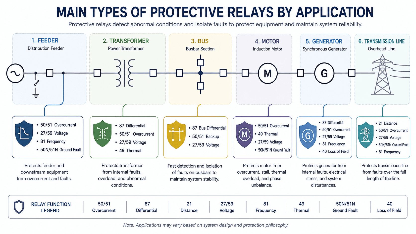
Modern numerical relays often contain many protection functions in one device. The function number identifies the protection logic; it does not necessarily represent a separate physical relay.
| Function | Device number | What it detects | Typical application |
|---|---|---|---|
| Instantaneous overcurrent | 50 | Current above pickup with little intentional delay | Fast clearing for high-current faults where coordination permits |
| Time overcurrent | 51 | Current above pickup with intentional or inverse-time delay | Feeders, transformers, motors, and backup protection |
| Directional overcurrent | 67 | Overcurrent in a selected direction | Parallel feeders, looped systems, DER, and networks with multiple sources |
| Differential | 87 | Difference between current entering and leaving a defined zone | Transformers, buses, generators, motors, and line protection |
| Distance | 21 | Apparent impedance from relay location to fault | Transmission line protection zones |
| Undervoltage / overvoltage | 27 / 59 | Voltage outside acceptable limits | Motors, generators, buses, interconnections, system supervision |
| Frequency | 81 | Underfrequency, overfrequency, or frequency-rate conditions | Generation, islanding, load shedding, system stability schemes |
| Negative sequence | 46 | Unbalance and negative-sequence current | Generators and motors |
| Thermal | 49 | Thermal accumulation or heating effect | Motors, transformers, generators, cables |
| Synch-check | 25 | Voltage, frequency, and phase-angle conditions before closing | Breaker closing between energized buses or sources |
| Automatic reclosing | 79 | Post-trip reclosing logic | Overhead lines where many faults are temporary |
Swipe horizontally to view all table columns.
For detailed treatment of one of the most selective methods, see Differential Protection. For broader fault-current context, see Fault Analysis.
Protective Relay Coordination: Pickup, Timing, and Selectivity
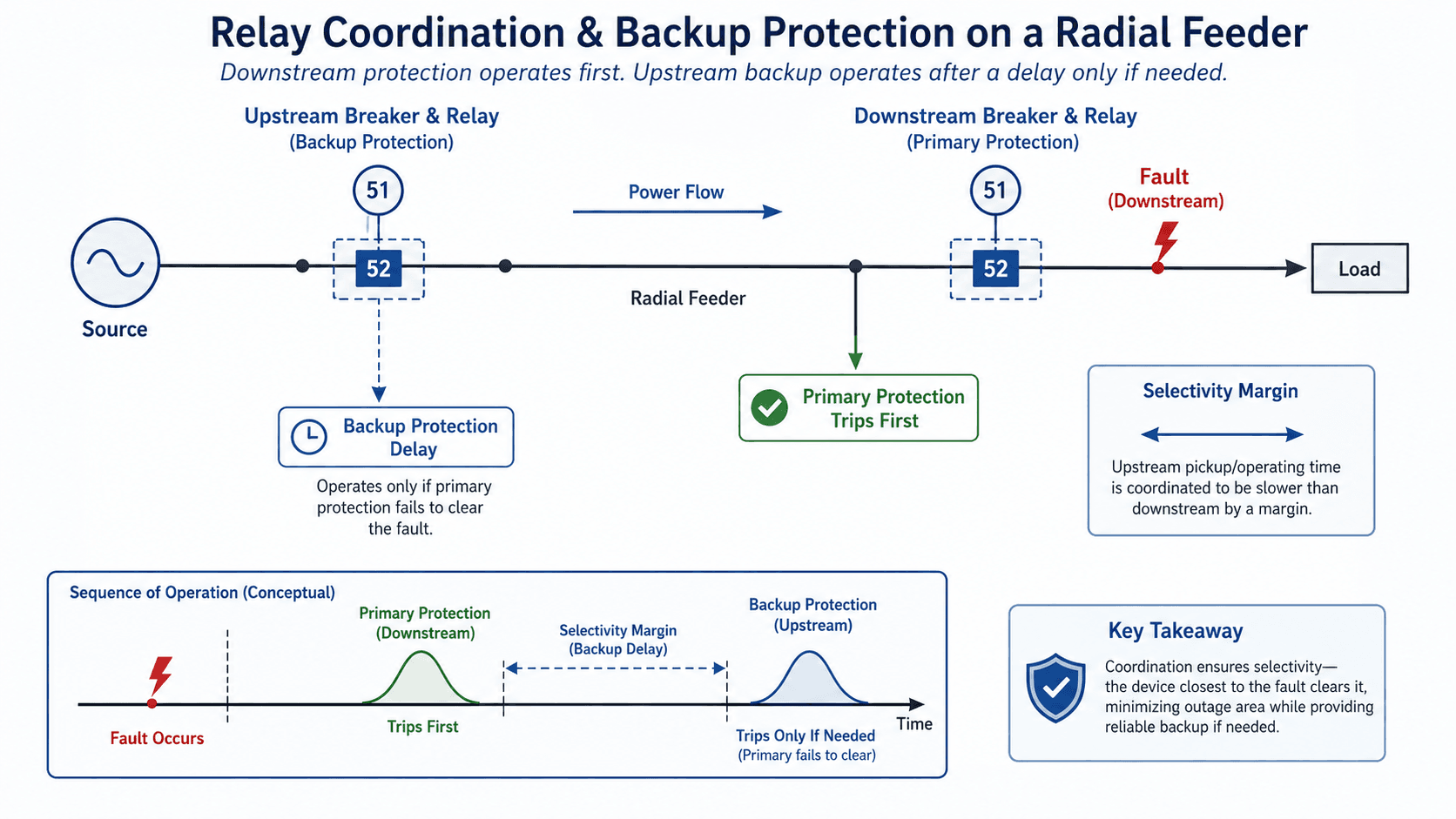
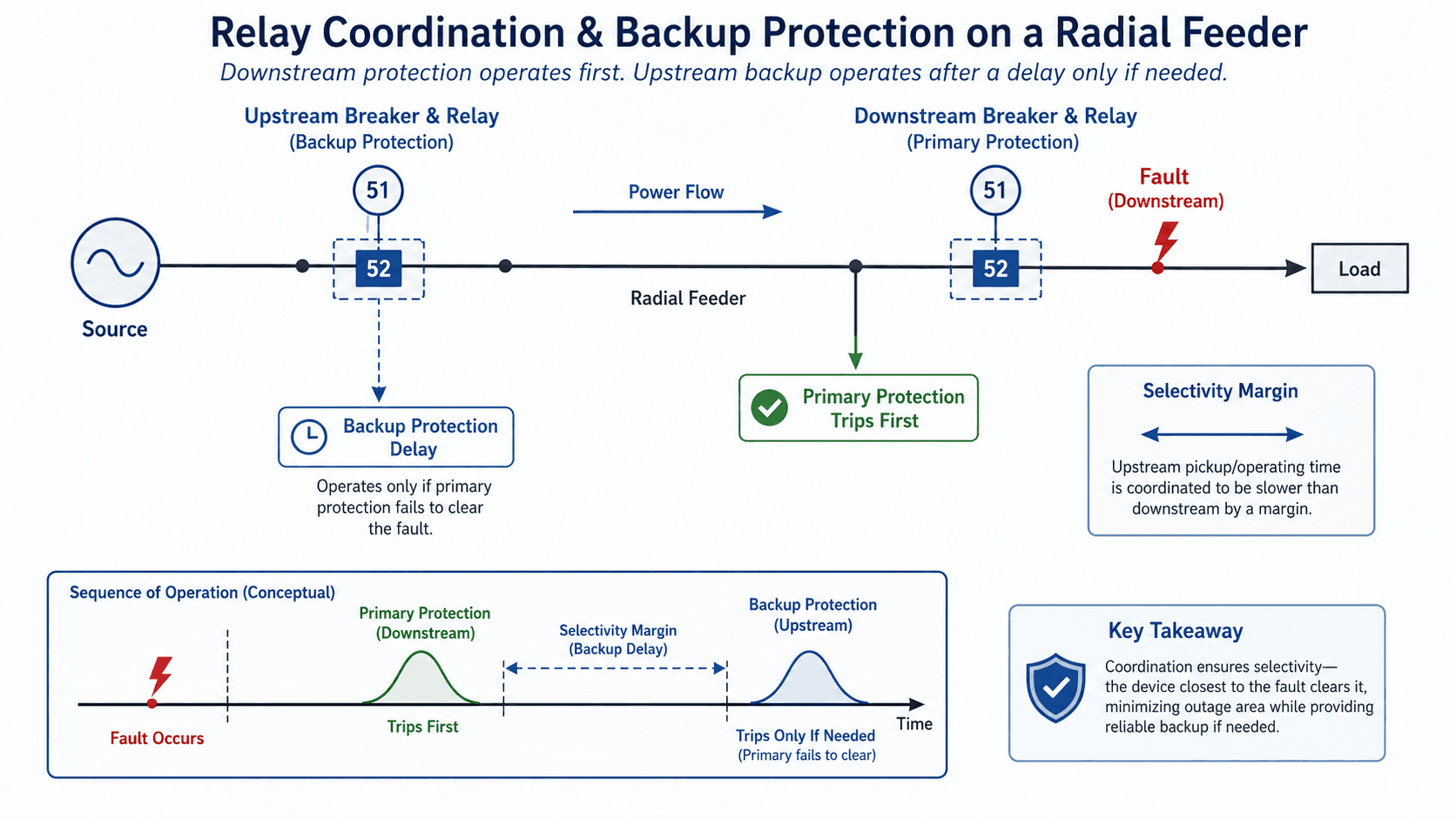
Coordination means the protection closest to the fault should normally clear first while upstream devices remain available as delayed backup.
-
Determine maximum load and minimum fault current.
The relay must avoid normal load and expected inrush while remaining sensitive to the lowest fault current it must detect.
-
Select pickup.
Pickup should be above acceptable operating current and below the minimum relevant fault level, subject to equipment and coordination constraints.
-
Select time curve and delay.
Inverse-time or definite-time settings allow downstream devices to operate first while preserving upstream backup.
-
Include breaker clearing time.
Relay operating time is only part of total fault-clearing time. Breaker opening and interruption must also fit the coordination margin.
-
Check alternate system conditions.
Tie breakers, generators, DER, source changes, maintenance configurations, and weak-source conditions can change fault magnitude and direction.
| Setting concept | Meaning | Main risk if wrong |
|---|---|---|
| Pickup | Threshold at which an element begins to operate | Too low: nuisance trips; too high: missed faults |
| Time delay | Intentional delay after pickup | Too short: loss of selectivity; too long: excessive fault duration |
| Curve family | Relationship between current magnitude and operating time | Poor matching with downstream fuses, reclosers, or relays |
| Instantaneous element | Fast high-current element | Overreach into downstream zones if set too low |
| CT ratio | Primary-to-secondary current conversion used by relay | Every current-based setting can be wrong if ratio is wrong |
Swipe horizontally to view all table columns.
NERC PRC-027-1 addresses coordination of protection systems so protective devices installed to detect and isolate faults operate in the intended sequence on Bulk Electric System elements: NERC PRC-027-1.
Where Protective Relays Are Used
Protective relays are applied wherever faults or abnormal operating conditions could damage equipment, destabilize the system, or create unacceptable outage risk.
| Equipment | Common protection | Typical engineering concern |
|---|---|---|
| Distribution feeder | 50/51, ground fault, directional overcurrent, reclosing | Selective clearing, minimum fault sensitivity, DER impact, restoration |
| Transformer | 87T differential, overcurrent, restricted ground fault, thermal, pressure-related protection | Internal faults, inrush restraint, CT mismatch, backup protection |
| Bus | Bus differential, breaker failure, backup overcurrent | Very fast clearing, CT saturation, zone definition |
| Motor | 49 thermal, 46 negative sequence, overcurrent, ground fault, undervoltage | Locked rotor, overload, unbalance, starting current |
| Generator | Differential, reverse power, loss of field, frequency, voltage, negative sequence | Machine damage, excitation failure, synchronization, system disturbances |
| Transmission line | 21 distance, line differential, directional comparison, pilot schemes, backup overcurrent | Fast selective line clearing, communication dependency, power swings, source changes |
Swipe horizontally to view all table columns.
For line-specific protection, see Transmission Line Protection.
Electromechanical, Static, and Numerical Protective Relays
Protective relays have evolved from mechanical measurement elements to microprocessor-based devices that can combine protection, logic, metering, oscillography, event recording, communications, and automation in one platform.
| Relay type | How it works | Strengths | Limitations |
|---|---|---|---|
| Electromechanical | Coils, induction disks, magnetic forces, springs, contacts | Rugged, intuitive, visible operation | Limited functionality, mechanical wear, calibration drift |
| Static | Analog electronic measurement and logic | Faster operation and fewer moving parts | Less flexible than numerical devices; aging electronics |
| Numerical / digital | Digitally samples inputs and applies software-based protection logic | Multiple functions, event records, metering, logic, communications | Settings management, firmware, cybersecurity, configuration complexity |
Swipe horizontally to view all table columns.
A numerical relay can contain dozens of functions, but only the enabled, correctly configured, correctly mapped, and properly tested functions actually protect the system.
IEC 60255-1 establishes common requirements for measuring relays and protection equipment used in power-system protection schemes: IEC 60255-1.
Protective Relay Testing, Commissioning, and Maintenance
A relay should be tested as part of the complete protection scheme, not only as a standalone device.
-
Verify settings and configuration.
Check CT/VT ratios, enabled elements, pickup, timing, logic equations, setting groups, communications, and output mapping.
-
Perform injection testing.
Secondary injection can verify pickup, timing, directional behavior, differential restraint, voltage/frequency elements, and metering.
-
Test the complete trip path.
Verify the relay output, DC control power, lockout relay if used, trip coil, breaker auxiliary contacts, and actual breaker operation.
-
Verify communication-assisted schemes.
End-to-end testing checks permissive, blocking, line differential, teleprotection, time synchronization, and channel behavior.
-
Review event records after operations.
Oscillography, sequence-of-events records, relay targets, and breaker status help determine whether a trip was correct, delayed, unwanted, or caused by a settings or wiring problem.
A relay target or trip LED proves only that the relay logic asserted an output. It does not prove that the breaker opened, the fault cleared, or the intended protection zone was isolated.
Protective Relay Field Review Checklist
The highest-value relay review is usually a complete signal-to-action check that compares drawings, settings, wiring, breaker behavior, and actual system configuration.
| Check | What to verify | Failure risk |
|---|---|---|
| Protected zone | CT locations, breaker boundaries, primary/backup reach | Blind spot, overreach, or wrong breaker operation |
| CT ratio and polarity | Installed ratio, wiring polarity, residual/neutral connections | False trips, missed faults, wrong directional/differential operation |
| VT/PT source | Ratio, phase rotation, fuse status, grounding, source side | Wrong voltage magnitude or angle used in logic |
| Pickup and timing | Maximum load, inrush, motor starting, minimum fault current, coordination margins | Nuisance operation or inadequate sensitivity |
| Trip circuit | DC source, fuses, lockout relay, trip coil, auxiliary contacts, supervision | Relay trips but breaker does not open |
| Enabled logic | Setting group, element enables, logic equations, blocking bits, output contacts | Protection function exists in hardware but is not actually active |
| System configuration | Tie status, generators, DER, temporary feeds, alternate operating modes | Fault magnitude or direction no longer matches study assumptions |
| Post-event data | Oscillography, SOE, targets, breaker timing, communication status | Incorrect root-cause conclusion after a trip |
Swipe horizontally to view all table columns.
Protection can become outdated after transformer replacements, utility source changes, DER additions, generator changes, feeder reconfiguration, or breaker upgrades. Material system changes should trigger a review of fault current, coordination, and relay settings.
Protective Relay Engineering References
Protective relay design and settings must be tied to applicable standards, equipment manuals, utility criteria, short-circuit studies, coordination studies, and commissioning procedures.
- IEC 60255-1 — Measuring Relays and Protection Equipment Common requirements for measuring relays and protection equipment used in power-system protection.
- NERC PRC-027-1 — Coordination of Protection Systems Coordination requirements for protection systems so faults are isolated in the intended sequence on the Bulk Electric System.
- NERC — Protection and Control Standards Current protection and control standards covering coordination, relay performance, maintenance, misoperations, and fault behavior.
Frequently Asked Questions
What is the main purpose of a protective relay?
A protective relay detects faults or abnormal electrical conditions and issues a trip, alarm, blocking, or control command so the affected equipment can be isolated or protected.
Does a protective relay interrupt fault current?
Usually no. The relay makes the protection decision and commands a breaker, recloser, or other interrupting device that physically opens the circuit.
What is the difference between 50 and 51 relays?
A 50 element is instantaneous overcurrent protection with little intentional delay. A 51 element is time-overcurrent protection that adds a time delay, often using an inverse-time curve, to coordinate with other devices.
What is an 87 differential relay?
An 87 differential element compares current entering and leaving a defined protection zone. A significant mismatch can indicate an internal fault inside equipment such as a transformer, bus, generator, motor, or line.
Why is relay coordination important?
Coordination allows the protection closest to the fault to operate first while upstream devices remain available as delayed backup. This limits outage area and avoids unnecessary tripping of healthy equipment.
What information is needed to set a protective relay?
Typical inputs include a current one-line diagram, CT/VT ratios, maximum load, minimum and maximum fault current, equipment ratings, breaker clearing time, protected-zone boundaries, operating configuration, and the required coordination or protection philosophy.
Summary and Next Step
Protective relays are the measurement and decision layer of power-system protection. They monitor electrical quantities, apply protection logic, and command breakers or other devices to isolate faults and abnormal operating conditions.
Strong relay protection depends on more than the relay itself: protection zones, CT/VT performance, settings, coordination, DC control power, breaker clearing time, communications, testing, and system configuration all determine whether the scheme works correctly.