Key Takeaways
- Core idea: Voltage regulation measures how well delivered voltage stays near its intended value as load and operating conditions change.
- Engineering use: Engineers use it to evaluate transformers, feeders, customer voltage, regulator settings, load flow results, and voltage-control equipment.
- What controls it: Load current, impedance, power factor, reactive power flow, tap settings, feeder length, and distributed generation all affect voltage.
- Practical check: A good result must be checked against voltage location, load case, equipment ratings, operating limits, and field behavior.
Table of Contents
Introduction
Voltage regulation is the ability of a power system, transformer, generator, or distribution feeder to maintain voltage near its intended value as load changes. It is both a percent calculation and a practical operating objective because poor regulation can cause low customer voltage, overvoltage, motor starting problems, nuisance trips, equipment stress, and inefficient power delivery.
Why Voltage Changes When Load Changes
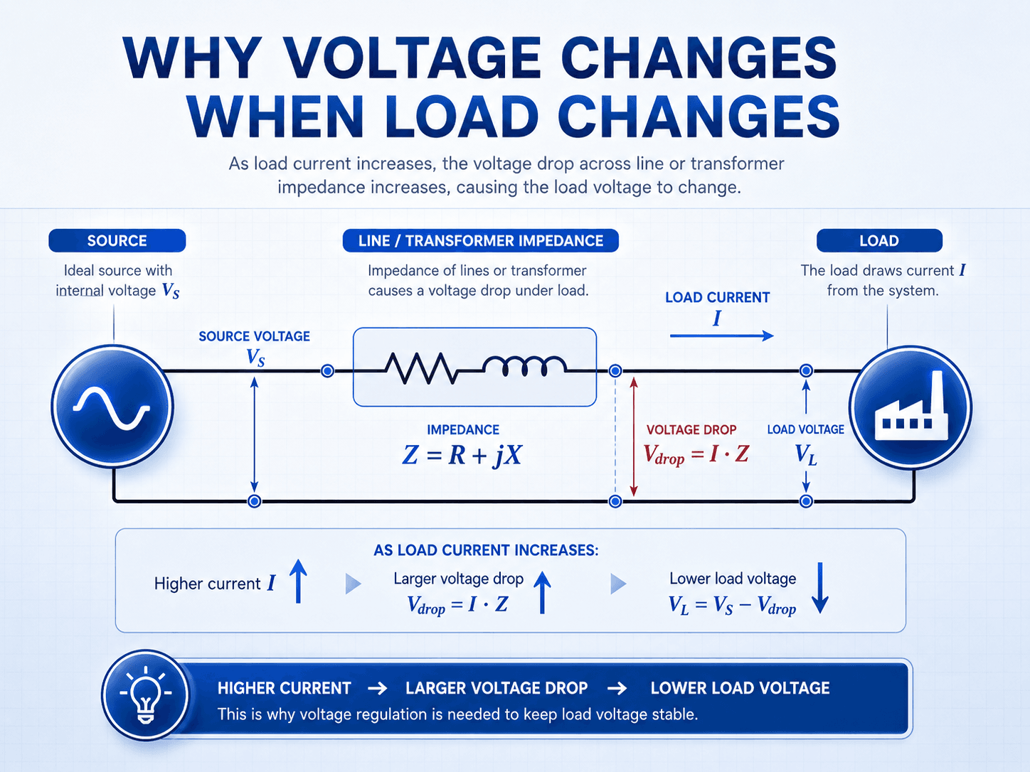
Read the diagram from left to right: the source supplies voltage, impedance creates a drop as current increases, and the load receives a lower voltage unless the system has enough voltage-control support.
What Is Voltage Regulation?
Voltage regulation describes how much delivered voltage changes between operating conditions. For a transformer, generator, or power supply, it is commonly expressed as the percent change from no-load voltage to full-load voltage. For a distribution feeder or power system, it also describes the practical control of voltage so buses and customers remain within an acceptable operating range.
The important engineering point is that voltage regulation is location-dependent. A substation bus can look acceptable while the end of a long feeder is low. A transformer secondary can regulate well at light load but sag under peak load. A solar-heavy feeder can have acceptable voltage during evening load but high voltage during midday export.
| Use of the term | Meaning | Common power systems context |
|---|---|---|
| Percent voltage regulation | The calculated voltage change between no-load and loaded operation. | Transformers, generators, power supplies, and introductory power systems calculations. |
| System voltage regulation | The process of keeping voltage within an acceptable operating band as load and generation change. | Distribution feeders, substations, customer service voltage, voltage regulators, capacitors, and smart inverters. |
Voltage regulation is not only about keeping a number close to nominal voltage. It is about keeping equipment and customer voltage usable across the actual load range, power factor range, tap settings, and operating scenarios the system will experience.
Voltage Regulation Formula
The common percent voltage regulation equation compares the voltage at no load with the voltage at full load. This version is often used for transformers, generators, and introductory power systems calculations.
- \(V_{no\text{-}load}\) Voltage measured or calculated when the load current is approximately zero, usually in volts or per unit.
- \(V_{full\text{-}load}\) Voltage measured or calculated at the specified load condition, usually rated load or the scenario being evaluated.
- \(\%VR\) Percent voltage regulation. A smaller positive value usually means voltage changes less from no load to full load.
Some transformer references use no-load voltage in the denominator instead of full-load voltage. Always check the convention used by the textbook, manufacturer data sheet, utility standard, or project calculation template before comparing results.
In feeder studies, engineers often think in terms of voltage drop and voltage profile instead of only no-load versus full-load regulation. A simplified relationship is:
This simplified expression shows the central idea: load current \(I\) flowing through impedance \(Z\) creates voltage drop. In real AC systems, resistance, reactance, phase angle, power factor, transformer taps, and reactive power support determine the actual voltage profile.
Transformer Voltage Regulation
Transformer voltage regulation describes how much the secondary voltage changes from no load to load. Even if the primary voltage is steady, the transformer secondary voltage can drop because load current flows through winding resistance and leakage reactance inside the transformer.
Transformer impedance, load current, and load power factor all matter. A resistive load, inductive motor load, and capacitive load can create different secondary-voltage behavior even when the apparent power is similar. That is why transformer voltage regulation is usually evaluated with both load magnitude and power factor in mind.
| Transformer condition | Typical voltage behavior | Engineering implication |
|---|---|---|
| Light load | Secondary voltage is usually close to the no-load value. | Voltage may appear acceptable even if the transformer will sag under peak load. |
| Full load at lagging power factor | Voltage drop is usually more noticeable because reactive current interacts with leakage reactance. | Motor-heavy loads may need closer voltage review than a simple kW-only check suggests. |
| Leading power factor | Voltage drop can be reduced and, in some cases, voltage can rise. | Over-applied capacitors or inverter VAR settings can create unexpected voltage behavior. |
| High transformer percent impedance | More internal voltage drop occurs for the same load current. | Short-circuit duty may be lower, but voltage regulation can be less stiff under load. |
When transformer voltage regulation looks poor, check the actual loading, transformer percent impedance, tap position, power factor, and whether the measured low voltage is caused by the transformer or by downstream conductors.
Voltage Regulation vs Voltage Drop
Voltage regulation and voltage drop are related, but they are not the same thing. Voltage drop is a loss of voltage across impedance while current flows. Voltage regulation describes how well the system maintains voltage as load or operating conditions change.
| Concept | What it describes | How engineers use it |
|---|---|---|
| Voltage drop | The voltage difference between two points caused by current flowing through conductor, cable, line, or transformer impedance. | Used to check feeders, branch circuits, cables, transformer secondaries, long runs, and end-of-line voltage. |
| Voltage regulation | The change in delivered voltage between operating conditions, or the system’s ability to hold voltage near a target range. | Used to evaluate transformers, generators, distribution feeders, regulator settings, capacitor placement, and voltage-control performance. |
| Voltage stability | The ability of the power system to maintain acceptable voltages after disturbances or under stressed reactive power conditions. | Used in broader system planning and stability studies, especially when reactive support and load behavior become limiting. |
A voltage drop calculation may explain why voltage is low at one point, but it does not by itself prove that the whole system has acceptable voltage regulation across all load conditions.
How Load Current, Impedance, and Power Factor Affect Voltage Regulation
Voltage regulation becomes worse when a system has high current, high impedance, or operating conditions that increase reactive voltage drop. The most important physical mechanism is simple: current must flow through conductors, transformer windings, and other equipment that have resistance and reactance.
Line and transformer impedance
Every feeder, cable, transformer winding, and connection has impedance. Resistance contributes to real power loss and voltage drop. Reactance affects voltage drop differently depending on current phase angle. That is why two loads with the same current magnitude can create different voltage behavior if their power factors are different.
Lagging and leading power factor
Inductive loads such as motors commonly operate at lagging power factor, which can increase voltage drop across system reactance. Leading power factor can sometimes reduce drop or create voltage rise, especially when capacitor banks or inverter VAR controls are over-applied.
| Load condition | Typical effect on voltage regulation | Why it matters |
|---|---|---|
| Unity power factor | Voltage drop mainly follows the resistive and total impedance path. | Useful reference case, but many real loads are not exactly unity power factor. |
| Lagging power factor | Usually worsens voltage regulation. | Reactive current increases voltage drop across reactance, especially on inductive feeders and transformers. |
| Leading power factor | Can reduce voltage drop or produce negative regulation. | Capacitive current can offset reactive voltage drop or cause voltage rise under some conditions. |
| Solar or DER export | Can create voltage rise instead of voltage drop. | Reverse power flow can change how regulators, line drop compensation, and inverter controls behave. |
Load changes over time
Distribution systems rarely operate at one fixed load. Morning ramp, industrial motor starts, HVAC peaks, evening residential load, capacitor switching, and solar export can all move voltage up or down. A voltage regulation review should therefore consider more than one operating case.
Voltage Regulation in a Distribution Feeder
Distribution feeder voltage regulation is the process of keeping customer voltage within an acceptable band from the substation to the end of the feeder. The farther a load is from the source, the more line impedance and load current can affect the delivered voltage. Engineers often evaluate this with a load flow analysis because bus voltages, reactive power, and feeder loading interact throughout the system.
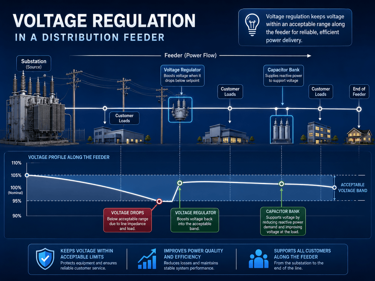
In a planning or operations study, engineers may review the voltage profile under peak load, light load, contingency operation, motor starting, or distributed energy export. A feeder can need voltage boost during heavy load and voltage reduction or VAR absorption during high solar export.
Regulator setpoint and regulation point
A voltage regulator does not make the entire feeder perfect. It controls voltage at its sensing point or calculated regulation point. Customers before and after that point may see different voltage behavior, especially when load distribution changes along the feeder.
Line drop compensation can estimate voltage farther downstream by using current and impedance settings, but it can be misleading if the load shifts, the feeder is reconfigured, or distributed generation reverses power flow. This is why regulator setpoint, bandwidth, time delay, line drop compensation, and reverse-flow settings must be reviewed together.
End-of-line voltage complaints often show up only during certain hours, seasons, or operating states. A single spot measurement may miss the worst condition unless the load pattern, feeder switching state, regulator tap position, and capacitor status are understood.
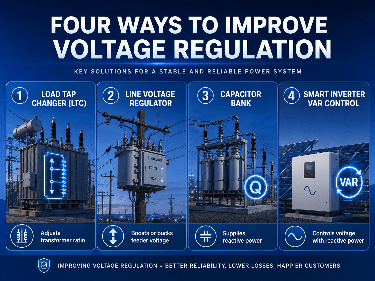
Common Methods Used to Improve Voltage Regulation
Voltage regulation can be improved by reducing voltage drop, changing voltage setpoints, adding reactive power support, or controlling how voltage responds to load and generation changes. The best method depends on whether the problem is steady low voltage, voltage rise, reactive power demand, conductor impedance, or poor control coordination.
| Method | What it changes | Best use case | Watch for |
|---|---|---|---|
| Load tap changer | Adjusts transformer ratio to raise or lower secondary voltage. | Substation or transformer voltage control across changing load levels. | Coordination with downstream regulators and avoiding excessive tap operations. |
| Line voltage regulator | Boosts or bucks feeder voltage at a selected point along the line. | Long feeders, rural feeders, and end-of-line low voltage conditions. | Setpoint, bandwidth, time delay, line drop compensation, reverse power flow, and regulator hunting. |
| Capacitor bank | Supplies reactive power locally and can reduce reactive current flow. | Feeders with lagging power factor, high reactive demand, or voltage sag under load. | Overvoltage at light load, switching transients, harmonics, and poor placement. |
| Conductor or feeder upgrade | Reduces impedance by using larger conductors, shorter routing, or stronger source paths. | Voltage drop problems caused mainly by long runs or undersized conductors. | Cost, constructability, outage planning, and whether reactive power is the real issue. |
| Smart inverter VAR control | Absorbs or supplies reactive power to influence local voltage. | Feeders with solar, storage, or inverter-based distributed energy resources. | Utility requirements, control settings, capability limits, and interaction with other devices. |
Worked Voltage Regulation Example
A transformer secondary measures 244 V at no load and 232 V at full load. Using full-load voltage as the reference, the percent voltage regulation is:
If the calculation convention uses no-load voltage as the reference, the same measurements give:
How to interpret the result
Both results show that the delivered voltage changes by about five percent between no load and full load. The engineering interpretation is similar, but the reference convention must be stated so results are not compared incorrectly.
Why the example is not the whole design check
The formula gives a useful comparison, but it does not show where the voltage drop occurs. In a real system, the transformer, service conductors, feeder, motor load, capacitor bank, and regulator settings may each contribute to the final voltage seen by the load.
What Is a Good Voltage Regulation Percentage?
A “good” voltage regulation percentage depends on the equipment, system voltage level, project criteria, and operating case. Lower regulation usually means a stiffer voltage source, but a single percentage should not be treated as a universal pass or fail limit.
| Result pattern | General interpretation | Engineering caveat |
|---|---|---|
| Near 0% | Very little voltage change between operating points. | May indicate a stiff source, light loading, or an idealized calculation case. |
| Low single digits | Often reasonable for many equipment-level examples. | Still must be compared to equipment requirements, utility criteria, and the actual location of the load. |
| Higher positive value | Voltage is dropping more noticeably under load. | Check load current, feeder length, conductor size, transformer impedance, and power factor. |
| Negative regulation | Voltage rises under the evaluated condition instead of dropping. | Can occur with leading power factor, capacitor over-application, light load, or distributed generation export. |
Do not evaluate voltage regulation by percentage alone. Check whether the actual voltage remains acceptable at the equipment terminals, service point, bus, or feeder location that matters for the study.
Common Causes of Poor Voltage Regulation
Poor voltage regulation usually means the system voltage changes too much between load conditions or cannot stay within the required voltage band. The cause may be electrical, operational, or control-related.
| Cause | What happens | Typical engineering response |
|---|---|---|
| Long feeder or service run | Voltage falls as current flows through line impedance. | Review conductor size, feeder routing, voltage regulator placement, or load transfer options. |
| High load current | Larger current creates larger voltage drop through the same impedance. | Check peak demand, load balancing, transformer loading, and conductor capacity. |
| Lagging power factor | Reactive current increases voltage drop across inductive reactance. | Evaluate capacitor banks, VAR support, motor loads, or power factor correction strategy. |
| Overloaded transformer | Transformer internal impedance causes secondary voltage to sag under load. | Review transformer rating, percent impedance, tap position, loading profile, and future growth. |
| Incorrect regulator settings | Voltage may hunt, remain too low, run too high, or regulate the wrong point. | Review setpoint, bandwidth, time delay, line drop compensation, and reverse-flow settings. |
| Distributed generation backfeed | Voltage can rise during export, especially on lightly loaded feeders. | Review smart inverter settings, regulator coordination, feeder hosting capacity, and utility interconnection rules. |
Voltage Regulation Sanity Check Table
Use this table when a voltage regulation calculation, load flow result, or field voltage measurement looks questionable. The goal is to identify whether the voltage issue is caused by load, impedance, reactive power, control settings, or the wrong operating scenario.
Start with the voltage location, then check the operating case, load current, power factor, system impedance, regulator/tap status, and reactive power support before deciding whether the solution is a settings change, equipment upgrade, conductor change, or study revision.
| Voltage regulation check | What to look for | Why it matters |
|---|---|---|
| Confirm the voltage location | Substation bus, transformer secondary, feeder midpoint, service entrance, or end-of-line load. | Voltage regulation can look acceptable at the source while still being poor at the farthest load. |
| Review load current and timing | Peak load, motor starting, seasonal HVAC load, industrial process load, or coincident demand. | Higher current increases voltage drop through the same impedance. |
| Check power factor | Lagging motor load, capacitor switching, leading conditions, or inverter VAR behavior. | Reactive current can strongly affect voltage drop and voltage rise in AC systems. |
| Inspect impedance assumptions | Transformer percent impedance, conductor size, feeder length, cable data, and per-unit base values. | Bad impedance data can make a voltage study appear precise while producing the wrong conclusion. |
| Verify control device settings | Tap position, regulator bandwidth, time delay, line drop compensation, capacitor control, and inverter setpoints. | Voltage-control devices can solve the problem or create hunting, overvoltage, or poor coordination. |
| Compare multiple scenarios | Heavy load, light load, reverse power flow, feeder switching, contingency operation, and future load growth. | A system may pass one case but fail another if the voltage-control strategy is not robust. |
Engineering Judgment and Field Reality
Real voltage regulation problems often appear as customer complaints, motor starting issues, nuisance equipment trips, inverter curtailment, or unexplained voltage alarms. The calculation may be straightforward, but the diagnosis usually requires understanding the operating state at the time of the problem.
Field voltage can change with feeder reconfiguration, capacitor bank status, regulator tap position, conductor temperature, transformer loading, distributed generation output, and customer load mix. In many cases, the hardest part is not calculating voltage regulation; it is choosing the operating case that actually represents the problem.
A voltage snapshot is useful, but a time-series trend is often better. Voltage complaints tied to solar export, HVAC peaks, or motor starts may disappear by the time a technician arrives unless the event is captured with logging or monitoring.
When This Breaks Down
Simplified voltage regulation calculations are useful for understanding the concept, but they can break down when the system behavior is dynamic, unbalanced, nonlinear, or controlled by multiple devices.
- Unbalanced three-phase feeders: A single average voltage may hide one phase that is low or high.
- Motor starting and transient events: Steady-state regulation does not fully capture short-duration voltage dips, inrush current, or recovery behavior.
- High distributed generation: Solar export can create voltage rise instead of voltage drop, especially on lightly loaded feeders.
- Multiple control devices: Tap changers, regulators, capacitors, and smart inverters can interact if setpoints and time delays are not coordinated.
- Harmonics and waveform distortion: Voltage magnitude alone does not describe all power quality problems.
Common Mistakes and Practical Checks
Many voltage regulation errors come from applying a correct formula to the wrong condition. A transformer percent regulation calculation, a feeder voltage drop calculation, and a load flow voltage profile each answer a different question.
- Using nominal voltage as proof of acceptable operation: Nominal voltage is a reference, not a guarantee that voltage stays acceptable under all load cases.
- Ignoring power factor: Lagging and leading conditions can change voltage behavior even when kW load appears similar.
- Checking only the source bus: The worst voltage is often downstream, especially near the end of long feeders or heavily loaded branches.
- Assuming capacitors always help: Capacitors can improve lagging reactive demand but may create overvoltage or switching issues if poorly applied.
- Not checking reverse power flow: Distributed generation can reverse feeder current and change how regulators and line drop compensation behave.
Do not treat a low percent voltage regulation value as a complete pass. The result still needs to be checked against the actual location, operating scenario, voltage band, equipment capability, and control settings.
Standards, Voltage Ranges, and Design References
Voltage regulation work often needs a reference point for nominal voltage ratings and operating voltage ranges. The engineering concept should be understood first, then project criteria, utility requirements, equipment ratings, and applicable standards can be used to judge whether voltage is acceptable.
| Voltage term | Meaning | Why it matters in voltage regulation |
|---|---|---|
| Nominal voltage | The named voltage class or reference voltage for the system. | Provides the baseline for discussing voltage range, equipment rating, and percent deviation. |
| Service voltage | Voltage at the service point or utility delivery point. | Helps distinguish utility-side voltage regulation from customer-side voltage drop. |
| Utilization voltage | Voltage at the equipment terminals after customer-side wiring voltage drop. | Determines what motors, controls, inverters, and utilization equipment actually experience. |
- ANSI C84.1: ANSI C84.1 electric power systems voltage ratings and operating tolerances provides a useful reference for nominal voltage ratings and operating tolerances for 60 Hz electric power systems above 100 V.
- Project-specific criteria: Utility service rules, owner requirements, interconnection agreements, equipment nameplates, and local design criteria may control the final acceptable voltage range.
- Engineering use: Engineers use voltage references alongside load flow studies, feeder voltage profiles, regulator settings, field measurements, and equipment ratings to decide whether voltage regulation is acceptable.
Frequently Asked Questions
Voltage regulation is the ability of a power system, transformer, generator, feeder, or voltage-control device to keep voltage close to its intended value as load changes. In calculations, it is often expressed as the percent change between no-load and full-load voltage.
A common percent voltage regulation formula is no-load voltage minus full-load voltage, divided by full-load voltage, multiplied by 100. Some transformer references use no-load voltage as the denominator, so the reference convention should always be stated.
No. Voltage drop is the reduction in voltage across conductors, transformers, or impedance while current flows. Voltage regulation describes how well the system maintains voltage over changing load conditions or how much voltage changes between reference operating points.
Poor voltage regulation is commonly caused by long feeders, high load current, undersized conductors, transformer impedance, lagging power factor, overloaded equipment, incorrect regulator settings, capacitor switching problems, or voltage rise from distributed generation.
Voltage regulation can be improved with transformer tap changes, line voltage regulators, capacitor banks, conductor upgrades, reactive power control, better load balancing, and smart inverter VAR control where distributed energy resources are present.
Summary and Next Steps
Voltage regulation explains how well voltage is maintained as load changes. In simple calculations, it compares no-load and full-load voltage. In real power systems, it is also a design and operations problem involving feeders, transformers, reactive power, tap settings, line regulators, capacitors, and inverter controls.
The most useful voltage regulation review checks the voltage location, load scenario, current, power factor, impedance data, regulator behavior, and field conditions. A good result is not just a small percentage; it is a system that keeps voltage acceptable across the operating cases that matter.
Where to go next
Continue your learning path with related Turn2Engineering resources.
-
Load Flow Analysis
Learn how bus voltages, voltage profiles, real power, reactive power, and equipment loading are evaluated in steady-state power system studies.
-
Distribution Lines
Review how feeder conductors, impedance, loads, and line length affect voltage delivery across distribution systems.
-
Power System Efficiency
Explore how losses, power factor, reactive power, and operating conditions affect efficient power delivery.