Key Takeaways
- Core idea: A control volume is a region chosen for analysis where mass and energy may cross the control surface.
- Engineering use: Engineers use control volumes to analyze turbines, compressors, pumps, nozzles, diffusers, heat exchangers, valves, and mixing chambers.
- What controls it: The boundary, inlet and outlet states, mass flow rates, heat transfer, work transfer, velocity, elevation, and steady-flow assumption control the balance.
- Practical check: A control-volume solution is only as good as the boundary you draw and the terms you justify keeping or neglecting.
Table of Contents
Introduction
A control volume is a selected region in space used to analyze an open thermodynamic system where mass crosses the boundary. Instead of following a fixed amount of matter, engineers draw a control surface around a device or flow region and balance mass, heat, work, and energy entering and leaving it.
Control Volume vs Control Mass
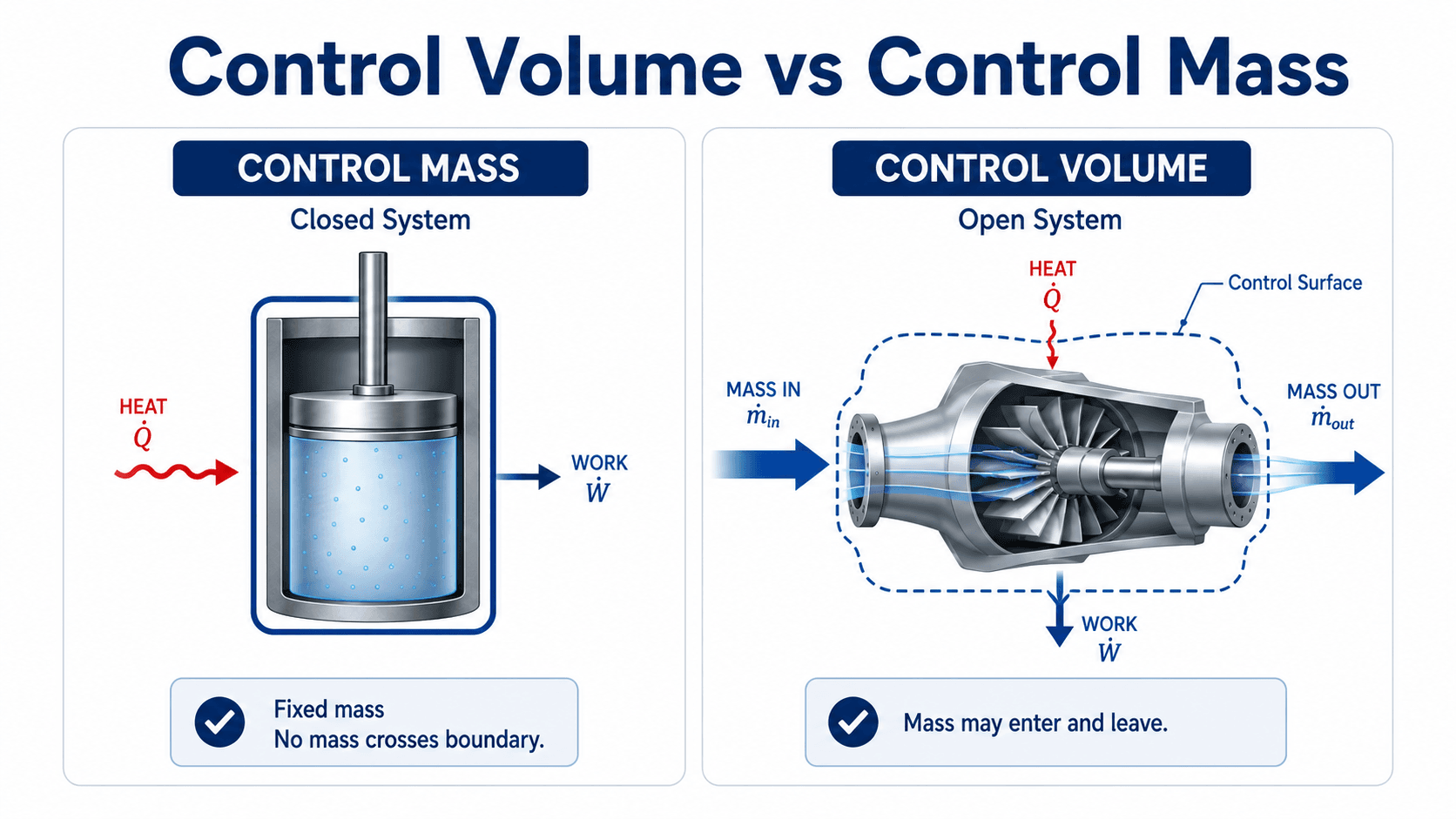
Notice the boundary first. In a closed system, the same mass remains inside the system. In a control volume, flow crosses the control surface, so the analysis must include mass-flow energy terms.
What is a Control Volume?
A control volume is an analysis region used in thermodynamics, fluid mechanics, and energy systems when mass may enter or leave the region. The boundary around that region is called the control surface. The boundary can follow a real piece of equipment, such as a pump casing, or it can be an imaginary surface drawn around a pipe junction, mixing chamber, or section of duct.
An open system is a thermodynamic system where mass can cross the boundary. Because that mass carries energy, open-system thermodynamics usually requires a control-volume approach instead of a closed-system equation.
Control Surface Meaning
The control surface is the boundary of the control volume. Every inlet, outlet, heat-transfer path, work interaction, leakage path, and moving boundary that crosses this surface must be included in the analysis. A poor control surface can make the equation look correct while the physical model is wrong.
Connection to the Reynolds Transport Theorem
Control-volume equations are connected to the Reynolds Transport Theorem, which converts conservation laws written for a system into equations written for a region in space. For most thermodynamics pages, the full derivation is not needed, but the idea matters: a control volume is a way to apply conservation of mass, energy, and momentum to flowing systems.
If mass crosses the boundary, treat the problem as a control-volume problem. If the same fixed mass remains inside the boundary, a closed system or control-mass model may be more appropriate.
How Control Volume Boundaries Work
The control surface is where all accounting happens. Mass may cross at inlets and outlets, heat may cross due to temperature difference, and work may cross through shafts, moving boundaries, electrical devices, or other mechanical interactions. The way the boundary is drawn determines what terms appear in the balance equations.
Fixed, moving, and deforming control volumes
Many introductory thermodynamics problems use a fixed control volume around a steady device, such as a turbine or heat exchanger. In more advanced problems, the control volume may move or deform, such as a filling tank, expanding jet, moving engine component, or unsteady flow region. The same conservation logic applies, but the accumulation and boundary terms become more important.
Real boundaries and imaginary boundaries
A control volume does not need to match the physical walls exactly. For a pump, the boundary might follow the casing. For a pipe tee, the boundary might cut through three pipe sections. For a nozzle, the boundary might include only the internal flow passage. A good boundary makes the known states easy to identify and avoids unnecessary unknowns.
Momentum balance context
In thermodynamics, control-volume problems usually focus on mass and energy. In fluid mechanics, the same control-volume idea is also used for momentum balances, such as forces on pipe bends, nozzles, jets, and turbomachinery.
Control Volume Selection Examples
Choosing the right control volume is an engineering decision. The best boundary is usually the one that captures the important physics while minimizing unknown heat, work, loss, and property terms.
| Problem | Good control volume | Why this boundary works |
|---|---|---|
| Turbine power | Around the turbine casing | Captures inlet state, outlet state, shaft work output, and any heat transfer across the casing. |
| Heat exchanger | Around one stream or around both streams | Changes whether heat transfer appears as an external term or as energy exchanged internally between streams. |
| Pump performance | Around the pump only, or around the pump plus connected piping | Determines whether the analysis includes only pump shaft work and pressure rise or also pipe losses and elevation change. |
| Mixing chamber | Around the mixing junction | Captures all inlet streams and the combined outlet state. |
| Filling tank | Around the tank | Requires unsteady accumulation terms because mass and energy inside the tank change over time. |
If the equation has too many unknowns, do not immediately assume the problem is impossible. Redraw the control volume and see whether a different boundary reduces unknown heat transfer, shaft work, pressure losses, or intermediate states.
Conservation of Mass for a Control Volume
The mass balance says that the rate of mass accumulation inside the control volume equals the total mass flow rate entering minus the total mass flow rate leaving. This is the first check in almost every open-system thermodynamics problem because the energy balance depends on the same inlet and outlet flows.
General Control Volume Mass Balance Equation
For steady-flow operation, the amount of mass inside the control volume does not change with time. The mass balance then simplifies to:
- \(m_{CV}\) Mass inside the control volume, usually in kg or lbm.
- \(\dot{m}\) Mass flow rate crossing the control surface, usually in kg/s, lbm/s, or slug/s.
- \(\rho A V\) Common flow relation for mass flow rate when density, area, and average velocity are known.
In a single-inlet, single-outlet steady-flow device, the inlet mass flow rate equals the outlet mass flow rate. In mixing chambers, manifolds, heat exchangers, and pipe networks, several inlets and outlets may need to be summed.
Control Volume Energy Balance
The energy balance extends the First Law of Thermodynamics to open systems. Instead of only tracking heat, work, and stored energy, the control-volume form also tracks the energy carried across the control surface by mass flow.
In the diagram below, first identify the dashed control surface, then follow each arrow crossing that boundary. Every crossing represents a term that may need to appear in the energy balance.
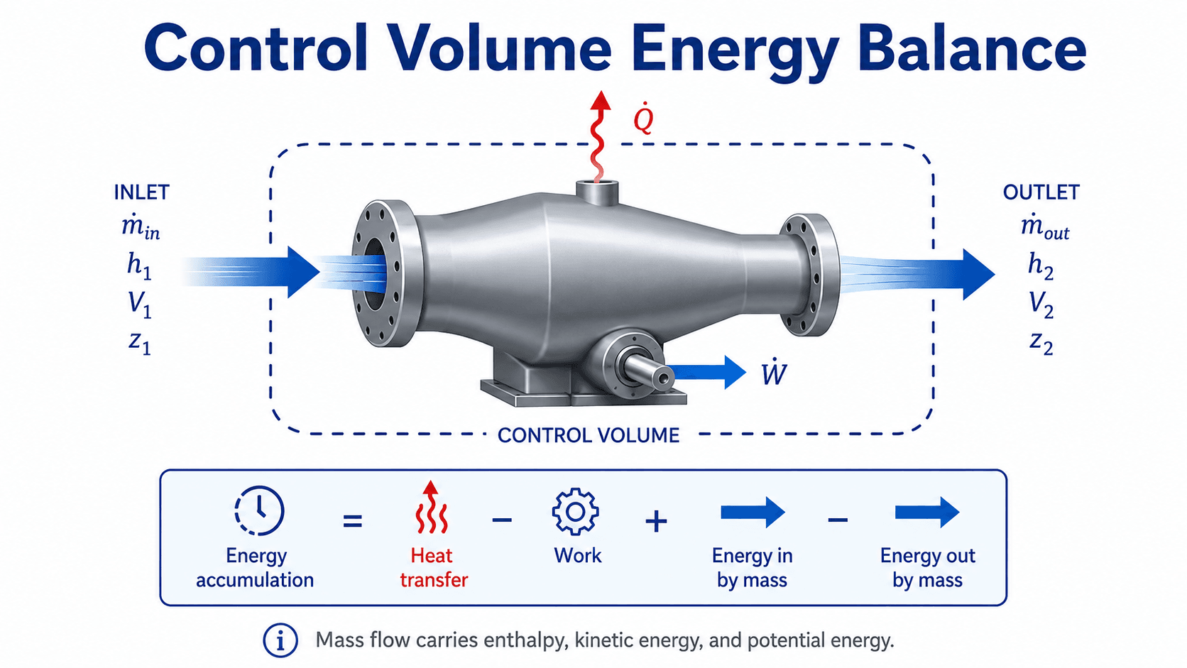
For many thermodynamics problems, the energy carried by flowing mass is expressed using enthalpy, kinetic energy, and potential energy. Enthalpy is especially important because it combines internal energy with the flow work needed to push mass across the control surface.
General Control Volume Energy Equation
This page uses the convention that \(\dot{Q}\) is positive into the control volume and \(\dot{W}\) is positive out of the control volume. If your textbook defines compressor work input as positive, the algebraic signs may look different even though the physics is the same.
- \(\dot{Q}\) Rate of heat transfer into the control volume, commonly in W, kW, Btu/hr, or horsepower.
- \(\dot{W}\) Rate of work transfer; in this page’s convention, \(\dot{W}\) is positive when work leaves the control volume, such as turbine shaft output.
- \(h\) Specific enthalpy, commonly in kJ/kg or Btu/lbm, including internal energy plus flow work.
- \(V^2/2\) Specific kinetic energy term, important in nozzles, diffusers, jets, and high-speed flow.
- \(gz\) Specific potential energy term, important when elevation changes are large enough to matter.
The signs and units must be handled consistently. In SI units, \(V^2/2\) gives J/kg, so divide by 1000 before combining it with enthalpy in kJ/kg. In real thermodynamics problems, enthalpy values usually come from steam tables, refrigerant tables, ideal-gas property tables, or validated property software.
Steady Flow Energy Equation
The steady flow energy equation is the most common control-volume equation used in introductory and applied thermodynamics. It applies when the properties inside the control volume do not change with time, even though mass and energy continue to flow through it.
This single-inlet, single-outlet form is useful for turbines, compressors, pumps, nozzles, diffusers, and many heat-transfer devices. The equation becomes much simpler when justified assumptions remove terms.
| Device or process | Common simplification | What engineers check before simplifying |
|---|---|---|
| Turbine | Often adiabatic with shaft work output. | Whether heat loss, velocity change, or pressure drop details are important to the required accuracy. |
| Compressor | Often treated as adiabatic with shaft work input. | Whether cooling, intercooling, or significant heat rejection changes the energy balance. |
| Pump | Pump-only control volumes often focus on shaft work and pressure rise. | Full pump-system control volumes may also require elevation change and pipe losses. |
| Nozzle | No shaft work; enthalpy converts to velocity. | Kinetic energy is usually important and should not be dropped automatically. |
| Heat exchanger | Usually no shaft work; heat moves between streams. | Whether the control volume encloses one stream or both streams changes the heat-transfer term. |
| Throttling valve | Often modeled with \(h_1 \approx h_2\). | This assumes negligible heat transfer, negligible kinetic and potential energy changes, and no shaft work. |
For more background on the property that makes open-system energy balances compact, see the Turn2Engineering guide to enthalpy. For thermal interactions across a boundary, the guide to heat transfer provides the supporting concept.
Steady vs Unsteady Control Volumes
The first major modeling decision is whether the control volume is steady or unsteady. A steady control volume can still have mass flow, heat transfer, and work transfer, but the amount of mass and energy stored inside the region does not change with time.
| Control volume type | What changes with time? | Common examples | Equation impact |
|---|---|---|---|
| Steady flow | Mass and energy stored inside the control volume remain approximately constant. | Turbines, pumps, compressors, nozzles, diffusers, and operating heat exchangers. | Accumulation terms are dropped from the mass and energy balances. |
| Unsteady flow | Mass, pressure, temperature, internal energy, or phase distribution changes with time. | Filling tanks, draining tanks, startup, shutdown, blowdown, and charging systems. | Accumulation terms must remain in the governing equations. |
Do not ask only whether flow exists. Ask whether the mass and energy stored inside the control volume are changing during the period being analyzed.
Common Control Volume Applications
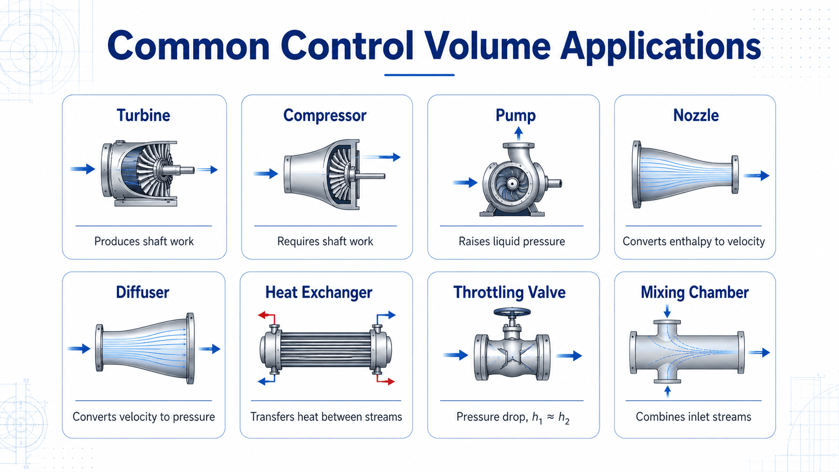
Control volumes are used whenever the useful engineering question is about a device, region, or flow passage rather than a fixed amount of matter. That is why the method appears throughout power generation, HVAC, refrigeration cycles, propulsion, process piping, and fluid machinery.
In the infographic below, focus on what each device changes. Some devices convert enthalpy into work, some require work input, and others mainly change velocity, pressure, temperature, or stream mixing.
| Device | Usually important | Often negligible | Main result |
|---|---|---|---|
| Turbine | Enthalpy drop and shaft work output. | Heat loss, potential energy, and sometimes kinetic energy. | Power output. |
| Compressor | Enthalpy rise and shaft work input. | Potential energy and sometimes kinetic energy. | Power input. |
| Pump | Shaft work, pressure rise, and sometimes elevation change. | Kinetic energy change in many pump-only analyses. | Liquid pressure increase or required pump power. |
| Nozzle | Enthalpy and kinetic energy. | Work, potential energy, and often heat transfer. | Exit velocity. |
| Diffuser | Kinetic energy reduction and pressure recovery. | Work and potential energy. | Pressure rise from slowing the flow. |
| Heat exchanger | Stream enthalpies and heat transfer between streams. | Shaft work, kinetic energy, and potential energy. | Outlet temperature, heat duty, or stream energy balance. |
| Throttling valve | Pressure drop and phase behavior. | Work, heat transfer, kinetic energy, and potential energy in the ideal model. | Outlet state with \(h_1 \approx h_2\). |
| Mixing chamber | Mass balance and stream enthalpies. | Shaft work and often heat transfer. | Mixed outlet state. |
Before solving a device problem, ask what the device is supposed to change: pressure, velocity, temperature, enthalpy, phase, composition, or shaft power. That usually tells you which energy terms deserve attention.
Which Control Volume Equation Should You Use?
A control-volume problem becomes easier when the modeling choice is made before the math starts. Use the physical situation to choose the equation form, then simplify it only after the boundary is clear.
Start with the boundary. If mass crosses it, use a control-volume model. If mass does not cross it, consider a closed-system model. Then decide whether the stored mass and energy are steady or changing with time.
| Situation | Use this model | Why |
|---|---|---|
| Mass crosses the boundary and conditions are steady. | Steady-flow control volume. | Mass and energy accumulation terms can usually be removed. |
| Mass crosses the boundary and tank pressure, level, or temperature changes. | Unsteady control volume. | Mass and energy stored inside the control volume are changing with time. |
| No mass crosses the boundary. | Closed system or control mass. | The same matter remains inside the system boundary. |
| The main question is force on a bend, jet, blade, or nozzle. | Momentum control volume. | Momentum flux and external forces control the answer. |
| The main question is shaft power, heat transfer, or outlet state. | Energy control volume. | Enthalpy, heat transfer, work transfer, velocity, and elevation terms control the result. |
How to Draw and Analyze a Control Volume
A strong control-volume solution starts before the equation. The most important work is choosing a useful boundary, labeling every crossing, and deciding which assumptions are justified.
Draw the device or flow region, sketch the control surface, label every inlet and outlet, add heat and work arrows, write the mass balance first, then write the energy balance and simplify only the terms you can defend.
| Step | What to do | Why it matters |
|---|---|---|
| 1. Choose the boundary | Draw the control surface around the device, pipe junction, tank, or flow region. | The boundary determines what crosses into and out of the analysis. |
| 2. Label all mass flows | Mark each inlet and outlet with \(\dot{m}\), pressure, temperature, velocity, elevation, and phase if known. | Missing one flow path causes both mass and energy balances to fail. |
| 3. Add heat and work | Show \(\dot{Q}\) and \(\dot{W}\) directions before assigning signs. | Sign convention errors are easier to catch visually than algebraically. |
| 4. Test steady-flow assumptions | Decide whether mass and energy stored inside the control volume change over time. | Steady-flow problems drop accumulation terms; transient problems do not. |
| 5. Simplify carefully | Drop kinetic energy, potential energy, heat transfer, or work terms only when the physics supports it. | Incorrect simplification can change the controlling term in the answer. |
| 6. Check units and meaning | Confirm that all terms are in compatible power units or energy-per-mass units. | A numerically clean answer can still be wrong if units or signs are inconsistent. |
Worked Example: Turbine Control Volume
Consider a steady-flow steam turbine with one inlet and one outlet. Steam enters at a specific enthalpy of \(3200 \, \text{kJ/kg}\) and exits at \(2500 \, \text{kJ/kg}\). The mass flow rate is \(5 \, \text{kg/s}\). Assume the turbine is adiabatic and changes in kinetic and potential energy are negligible.
Assumptions
- Steady-flow operation, so no mass or energy accumulation inside the turbine.
- One inlet and one outlet, so \(\dot{m}_{in} = \dot{m}_{out}\).
- No significant heat transfer, so \(\dot{Q} \approx 0\).
- Kinetic and potential energy changes are small compared with enthalpy change.
Engineering meaning
The turbine produces about \(3500 \, \text{kW}\) of shaft power under the stated assumptions. The result is positive because the fluid loses enthalpy as it expands through the turbine, and that energy decrease appears mainly as useful shaft work.
A turbine should usually have lower outlet enthalpy than inlet enthalpy when it produces shaft work. If the outlet enthalpy is higher in an adiabatic turbine problem, check the sign convention, inlet/outlet labeling, and property values.
Mini Example: Nozzle Exit Velocity
A nozzle is a useful reminder that kinetic energy cannot always be ignored. If a steady, adiabatic nozzle has no shaft work and negligible elevation change, the energy balance mainly relates enthalpy drop to velocity increase.
If inlet velocity is small compared with outlet velocity, the simplified relationship becomes:
Engineering meaning
A nozzle converts part of the fluid’s enthalpy into kinetic energy. Dropping the kinetic energy term in a nozzle problem would remove the main effect the device is designed to create.
Engineering Judgment and Field Reality
Textbook control-volume problems often make clean assumptions: steady operation, one inlet, one outlet, adiabatic walls, negligible pressure losses, and uniform velocity profiles. Real equipment may violate several of those assumptions at once. Heat loss, leakage, fouling, nonuniform flow, instrumentation error, and off-design operation can all change the balance.
Experienced engineers use the idealized equation as a starting point, then ask which neglected term is large enough to matter. In a large steam turbine, a small heat loss may be negligible relative to shaft power. In a small compressor with poor cooling assumptions, heat transfer may not be negligible. In a nozzle, kinetic energy is often the whole point of the analysis.
The control volume is not automatically the equipment casing. For troubleshooting, the better boundary may include upstream valves, downstream pressure losses, leakage paths, recirculation lines, or heat-transfer surfaces that are invisible in a simplified textbook sketch.
When This Breaks Down
Control-volume analysis is still based on conservation laws, but simplified control-volume equations can break down when the assumptions behind them are not true. The most common issue is using the steady-flow energy equation on a system that is actually accumulating mass, energy, or both.
- Transient filling or draining: Tanks, receivers, and startup conditions may require accumulation terms instead of steady-flow simplifications.
- Large velocity changes: Nozzles, diffusers, jets, and high-speed gas flow may require kinetic energy terms.
- Large elevation changes: Hydropower, pumping systems, and tall piping systems may require potential energy terms.
- Heat transfer is not negligible: Small devices, long ducts, poorly insulated lines, and heat exchangers may need explicit heat-transfer terms.
- Multiple phases or reactions occur: Boilers, condensers, evaporators, combustors, and reacting flows require careful property and phase accounting.
- Boundary choice hides important physics: Drawing the control surface too tightly or too broadly can omit losses, leaks, shaft work, or heat transfer.
Common Mistakes and Practical Checks
Most control-volume errors come from the setup, not the algebra. The equation is often straightforward once the boundary, signs, units, and assumptions are correct.
| Mistake | Why it causes problems | Practical check |
|---|---|---|
| Confusing control mass and control volume | A closed-system equation omits mass-flow energy terms. | Ask whether mass crosses the boundary. |
| Forgetting flow work | Open systems need enthalpy, not just internal energy. | Use \(h\) for flowing streams unless a derivation requires separate terms. |
| Dropping kinetic energy in nozzles | Velocity change may be the main output of the device. | Keep \(V^2/2\) when velocity is a design objective. |
| Using steady flow during startup | Mass and energy inside the control volume may be changing. | Check whether stored mass, pressure, temperature, or internal energy changes over time. |
| Mixing sign conventions | Work input and work output can flip signs depending on convention. | Draw arrows first, then keep the same convention through the whole solution. |
| Combining inconsistent units | Velocity, enthalpy, and elevation terms may not be in the same energy units. | Convert all specific-energy terms to J/kg, kJ/kg, ft·lbf/lbm, or Btu/lbm consistently. |
Do not simplify the steady-flow energy equation by habit. A pump, turbine, nozzle, heat exchanger, and throttling valve each keep and neglect different terms for different physical reasons.
Engineering References and Design Context
Control volumes are a foundational analysis method rather than a project-specific code requirement. A useful technical reference should explain the conservation-law form, show how enthalpy enters open-system analysis, and connect the equations to steady-flow devices.
- MIT thermodynamics notes: MIT control volume form of the conservation laws explains the control-volume form of conservation of mass and energy and shows how the steady-flow energy equation is developed for open systems.
- Property data: Real analyses often also require reliable steam tables, refrigerant tables, gas data, or software property models to obtain enthalpy, density, and state information.
- Engineering use: In design and troubleshooting, control-volume equations are paired with equipment data, measured pressures and temperatures, flow instrumentation, and a clearly stated sign convention.
Frequently Asked Questions
A control volume is a selected region in space used to analyze an open thermodynamic system. Mass, heat, work, and energy can cross the control surface, which lets engineers apply conservation of mass and energy to flow devices such as turbines, compressors, pumps, nozzles, and heat exchangers.
A control mass is a fixed amount of matter, so no mass crosses the system boundary. A control volume is a fixed or moving region where mass may enter and leave, making it the better choice for open systems with continuous flow.
Enthalpy is used because flowing mass carries both internal energy and flow work across the control surface. Combining those terms into enthalpy makes the steady-flow energy equation much easier to apply to turbines, compressors, pumps, nozzles, and heat exchangers.
A control volume can be treated as steady flow when the mass and energy stored inside it do not change with time. Flow rates, pressures, temperatures, and energy interactions may still exist, but the conditions at each location remain approximately constant during the analysis period.
The most common mistake is drawing the boundary without accounting for every mass, heat, and work interaction that crosses it. Missing an inlet, outlet, shaft work term, or important velocity change can make the mass or energy balance physically wrong even if the algebra looks correct.
Summary and Next Steps
Control volumes are the standard way to analyze open thermodynamic systems. Instead of following a fixed mass, the engineer selects a region, draws a control surface, and balances mass and energy crossing the boundary.
The most important workflow is to choose the boundary carefully, label every inlet and outlet, identify heat and work interactions, write the mass balance first, then apply the energy balance with only the assumptions that are physically justified.
Where to go next
Continue your learning path with related Turn2Engineering resources.
-
Open Systems
Learn how thermodynamic analysis changes when mass and energy can cross the system boundary.
-
Closed Systems
Compare control-volume analysis with closed-system analysis where no mass crosses the boundary.
-
Steady Flow Process
Review the steady-flow assumption used in turbines, compressors, pumps, nozzles, and heat exchangers.