
Key Takeaways
- Core idea: Insulation coordination keeps expected overvoltage stress below the withstand strength of transformers, breakers, cables, buswork, and other power equipment.
- Engineering use: It is used when selecting BIL, BSL, surge arresters, clearances, equipment ratings, and protective margins in substations and high-voltage systems.
- What controls it: System voltage, lightning exposure, switching duty, temporary overvoltage, arrester protective level, equipment insulation level, grounding, and physical layout all matter.
- Practical check: A surge arrester rating alone does not prove coordination; engineers must verify the voltage actually seen at the equipment terminals with adequate margin.
Table of Contents
Introduction
Insulation coordination is the process of selecting equipment insulation levels and overvoltage protection so power system equipment can withstand expected voltage stresses. It compares lightning, switching, temporary, and very-fast-front overvoltages against equipment withstand levels such as BIL and BSL, then verifies that surge arresters provide adequate protective margin.
Insulation Coordination Diagram: Stress, Withstand Level, and Margin
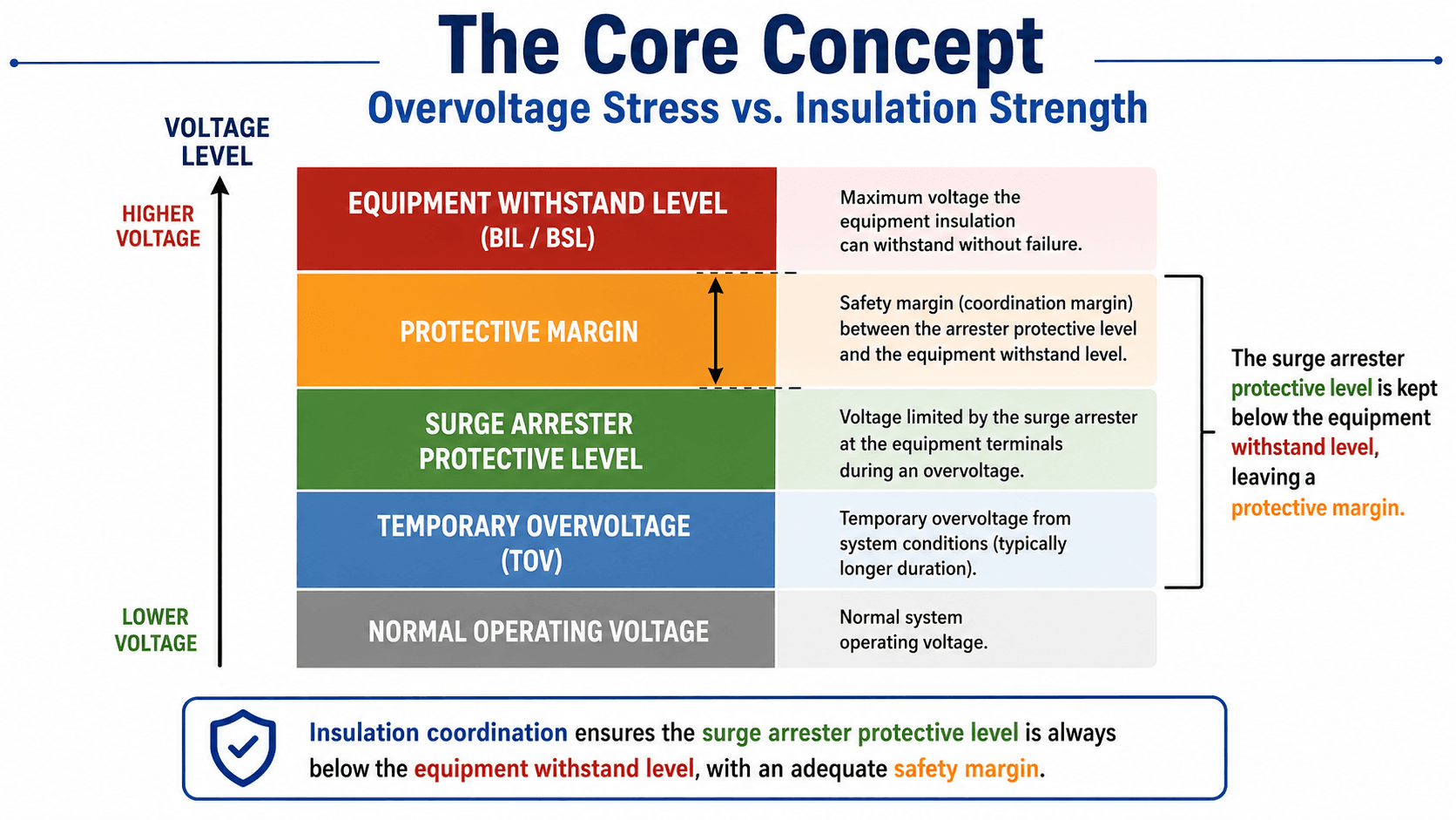
The most important relationship is not simply “higher BIL is better.” The useful check is whether the expected voltage at the equipment terminals remains below the equipment withstand level after surge arresters, grounding, and layout effects are considered.
What Is Insulation Coordination?
Insulation coordination is a power systems design process that matches the dielectric strength of equipment insulation with the overvoltage stresses that equipment is expected to experience. The goal is to reduce the probability of insulation failure while avoiding unnecessary equipment cost, clearance requirements, and overly conservative ratings.
In a substation, the process may involve transformer BIL, circuit breaker withstand voltage, bus insulation, cable terminations, surge arrester location, grounding, air clearances, GIS or AIS equipment type, and the expected frequency and severity of overvoltage events. The final design is a coordinated system, not a single equipment rating.
Insulation coordination is not relay coordination. Relay coordination decides which protective device trips during a fault. Insulation coordination decides whether the equipment insulation can survive expected voltage stress before protective devices, arresters, or natural system damping limit the event.
The Core Concept: Stress Must Stay Below Withstand Strength
The central insulation coordination idea is simple: the voltage imposed on equipment should remain below the insulation level that the equipment can withstand. The complexity comes from identifying which overvoltages matter, how often they occur, how they travel through the system, and what voltage remains at the protected equipment after surge protection and layout effects.
| Coordination level | What it represents | Engineering meaning |
|---|---|---|
| Normal operating voltage | The steady operating voltage of the system under normal conditions. | Equipment must continuously operate at this level without excessive stress, heating, or insulation aging. |
| Temporary overvoltage | A longer-duration voltage rise from ground faults, load rejection, resonance, or system configuration changes. | Surge arresters and insulation must tolerate the event long enough without thermal or dielectric failure. |
| Surge arrester protective level | The voltage that remains when the arrester conducts surge current and limits the overvoltage. | This should be low enough to protect the equipment, while still allowing the arrester to survive expected duty. |
| Protective margin | The gap between the equipment withstand level and the voltage reaching the equipment terminals. | This margin accounts for uncertainty, lead length, wave travel, tolerances, aging, modeling assumptions, and project criteria. |
| Equipment withstand level | The rated insulation strength of equipment, often discussed through BIL, BSL, and power-frequency withstand levels. | This is the upper boundary that expected overvoltage stress should not exceed for the selected risk level. |
Protective margin is the practical design check
A simplified educational expression for protective margin compares the equipment withstand voltage with the maximum protected voltage that can appear at the equipment after surge protection is applied.
In this expression, \(V_{\text{withstand}}\) represents the relevant equipment insulation withstand level, and \(V_{\text{protected}}\) represents the maximum expected voltage at the protected equipment terminals. Project standards may define margin using absolute kV, per-unit, statistical withstand probability, or utility-specific criteria, so this equation should be treated as a teaching model rather than a universal design formula.
Overvoltages Considered in Insulation Coordination
Insulation coordination is only useful when the expected voltage stresses are understood. A transformer, breaker, cable, or GIS bay may see different types of overvoltage, and each type has a different waveform, duration, source, and protection strategy.
| Overvoltage type | Typical source | Why it matters for insulation coordination |
|---|---|---|
| Power-frequency voltage | Normal system operation at rated frequency. | Sets the continuous electrical stress that equipment insulation must tolerate during normal service. |
| Temporary overvoltage (TOV) | Ground faults, load rejection, resonance, transformer energization, or system configuration changes. | Can last much longer than an impulse and can overheat or overstress surge arresters if MCOV and TOV duty are not selected correctly. |
| Fast-front overvoltage | Lightning strokes, backflashover, or lightning-induced traveling waves. | Often associated with BIL selection and surge arrester protection for transformers, breakers, and line entrances. |
| Slow-front overvoltage | Switching operations, line energization, reclosing, load rejection, and capacitor or reactor switching. | Important in higher-voltage systems where switching impulse withstand and system configuration strongly affect insulation stress. |
| Very-fast-front overvoltage | GIS disconnect switch operations and steep-front internal transients. | May require special attention in gas-insulated substations because steep wavefronts can create localized high-frequency stresses. |
The highest-looking voltage is not always the controlling case. Duration, waveform shape, equipment type, arrester response, grounding, and the physical distance between arrester and equipment can all change which overvoltage governs the coordination decision.
BIL vs BSL in Insulation Coordination
BIL and BSL are two of the most searched terms connected to insulation coordination. Both describe insulation withstand capability, but they apply to different impulse stresses. Understanding the difference helps prevent the common mistake of treating one insulation rating as if it covers every overvoltage condition.
| Term | Full name | Main stress type | Where it matters most |
|---|---|---|---|
| BIL | Basic Lightning Impulse Level | Fast-front lightning impulse stress. | Transformers, breakers, line entrances, cable terminations, and medium- or high-voltage substation equipment exposed to lightning surges. |
| BSL | Basic Switching Impulse Level | Slow-front switching impulse stress. | Higher-voltage transmission and EHV systems where line energization, reclosing, and switching operations can control insulation stress. |
| Power-frequency withstand | AC withstand level under specified test conditions | Short-duration AC insulation stress. | Equipment qualification, factory testing, field acceptance, and checking non-impulse withstand requirements. |
| Protective level | Voltage allowed by a surge arrester during a surge | Protected transient voltage at or near the equipment terminals. | Comparison against BIL, BSL, or other relevant withstand levels after layout and grounding effects are considered. |
BIL is important, but it is not the whole study
A common beginner mistake is treating BIL as the only insulation coordination decision. BIL addresses lightning impulse withstand, but a real coordination review may also need switching impulse behavior, temporary overvoltage duty, arrester energy capability, grounding quality, system configuration, and layout-specific separation effects.
Phase-to-Earth, Phase-to-Phase, and Longitudinal Insulation
Insulation coordination is not only about one voltage rating for an entire substation. Standards and equipment specifications distinguish different insulation paths because the voltage stress and failure mode can change depending on where the stress appears.
| Insulation path | Meaning | Power system example |
|---|---|---|
| Phase-to-earth insulation | Insulation between an energized conductor or terminal and grounded equipment, structure, tank, enclosure, or earth reference. | Transformer bushing conductor to grounded transformer tank, or bus conductor to grounded steel structure. |
| Phase-to-phase insulation | Insulation between energized conductors on different phases. | Air spacing between substation bus phases or phase-to-phase insulation inside switchgear. |
| Longitudinal insulation | Insulation across an open switching gap or between separated parts of the same phase path. | Open circuit breaker contacts, disconnect switch gaps, or equipment sections separated during switching operations. |
This distinction matters because a lightning surge, switching surge, open-gap stress, or temporary overvoltage may not stress every insulation path in the same way. A complete insulation coordination review should identify which path is being checked and which withstand level applies.
How Surge Arresters Fit Into Insulation Coordination
Surge arresters are one of the most important tools in insulation coordination because they limit transient overvoltages before those voltages overstress equipment insulation. During a surge, the arrester becomes conductive, diverts surge current to ground, and clamps the voltage to a lower protective level.
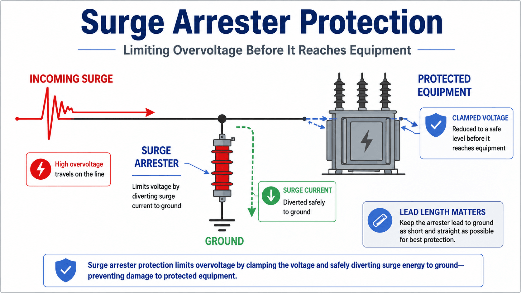
Arrester location can control the actual protection
The arrester protective level listed in a catalog is not automatically the same voltage seen by a transformer winding or breaker terminal. Surge waves travel through conductors, and voltage can build across leads, connections, and grounding paths. That is why arrester placement, short leads, and low-impedance grounding are practical insulation coordination issues.
MCOV and TOV duty must both be checked
A lower arrester protective level may look attractive, but the arrester must also survive normal operating voltage, temporary overvoltage, and expected surge energy. Insulation coordination is therefore a balance between protecting equipment and not applying an arrester beyond its continuous, temporary, or energy capability.
Protected zone is layout-dependent
Surge arrester protection is strongest near the arrester terminals and becomes less certain as the protected equipment is moved farther away. Long leads, indirect grounding paths, and large separation distances can consume protective margin before the surge reaches the equipment being protected.
Insulation Coordination Study Workflow
A practical insulation coordination study begins with the system voltage and equipment list, then works toward the voltage stresses and protective levels that each piece of equipment may experience. The workflow is iterative because arrester selection, equipment insulation level, station layout, and modeling assumptions can affect one another.
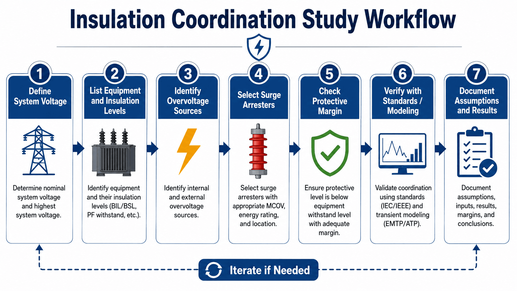
Step 1: Define the system voltage and equipment scope
Start with nominal voltage, highest voltage for equipment, grounding method, system configuration, and the equipment being protected. The insulation coordination scope may include transformers, switchgear, circuit breakers, disconnect switches, cables, terminations, instrument transformers, buswork, and line entrances.
Step 2: Identify credible overvoltage sources
The study should consider lightning exposure, switching operations, temporary overvoltages, ground faults, transformer energization, capacitor switching, reclosing, load rejection, and GIS-specific very-fast-front events where applicable. Not every source controls every project, but each credible source should be screened.
Step 3: Select surge protection and check margin
Choose surge arresters based on MCOV, duty, discharge current, protective level, energy capability, location, and grounding. Then compare the maximum expected protected voltage at the equipment terminals against the applicable insulation withstand level.
Step 4: Verify, iterate, and document
If the margin is not acceptable, the engineer may revise arrester location, select different arrester ratings, change equipment insulation levels, improve grounding, adjust the station layout, or perform more detailed transient modeling. The final study should document assumptions, inputs, equipment data, governing cases, margins, and limitations.
Insulation Coordination Study Inputs and Deliverables
A good insulation coordination study is only as reliable as its input data. The engineer needs enough information to define the voltage stress, the equipment withstand strength, the protective device behavior, and the physical layout between the surge source and the protected equipment.
| Study input | Where it usually comes from | Why it matters |
|---|---|---|
| Highest voltage for equipment | System design basis, voltage class, utility standard, or equipment specification. | Sets the insulation level family and prevents using ratings based on the wrong voltage class. |
| Equipment BIL, BSL, and withstand levels | Manufacturer data sheets, equipment standards, procurement specifications, and test reports. | Defines the insulation strength that protected overvoltages must remain below. |
| Surge arrester MCOV and protective level | Arrester manufacturer data and project arrester application criteria. | Determines whether the arrester can survive continuous/TOV duty and still limit surge voltage enough to protect equipment. |
| Grounding and bonding assumptions | Ground grid design, grounding study, layout drawings, and installation details. | Controls the surge current return path and can influence the voltage developed during discharge. |
| Arrester-to-equipment distance | Substation physical layout, one-line diagrams, elevation drawings, and cable or bus routing. | Affects the protected terminal voltage because traveling waves and lead voltage drops can consume protective margin. |
| Expected overvoltage sources | Lightning exposure, switching studies, operating procedures, utility criteria, and transient model cases. | Identifies which voltage stress actually governs the insulation coordination decision. |
What the completed study should document
A completed insulation coordination study should document the voltage basis, equipment list, applicable standards, overvoltage sources considered, equipment withstand levels, surge arrester data, grounding and layout assumptions, margin checks, modeling cases if used, and any limitations or owner-specific criteria.
IEC and IEEE Standards Used for Insulation Coordination
Standards provide the formal language and selection framework for insulation levels, but the engineering task is still project-specific. The most important references depend on voltage class, utility practice, equipment type, and whether the project follows IEC, IEEE, or owner-specific criteria.
A useful starting point is the IEC 60071-1 insulation coordination standard, which covers insulation co-ordination definitions, principles, and rules for three-phase AC systems above 1 kV.
| Reference family | What it supports | How it fits the study |
|---|---|---|
| IEC 60071-1 | Definitions, principles, rules, standard withstand voltage lists, and selection procedure for rated withstand voltages. | Frames how phase-to-earth, phase-to-phase, and longitudinal insulation withstand levels are selected for equipment and installations. |
| IEC 60071-2:2023 | Application guidance for determining rated withstand voltages for ranges I and II of IEC 60071-1. | Helps translate the principles of IEC 60071-1 into practical insulation level selection and coordination review. |
| IEEE C62.82.1 | Selection of withstand voltages, including BIL and BSL, for AC systems above 1 kV. | Often used in IEEE-based or North American practice when selecting phase-to-ground and phase-to-phase insulation levels. |
| Surge arrester application guides | Arrester rating, MCOV, discharge behavior, protective levels, and application considerations. | Used to verify that the protective device can both protect equipment and survive expected system duty. |
| Owner or utility standards | Project-specific margins, preferred BIL levels, acceptable equipment ratings, and modeling requirements. | Often control final acceptance even when the general study follows IEC or IEEE principles. |
Senior Engineer Review Checklist for Insulation Coordination
A strong insulation coordination review does more than compare one arrester rating to one BIL value. It checks whether the selected equipment, protective devices, physical layout, and study assumptions work together under the expected overvoltage cases.
Define voltage class → list protected equipment → identify overvoltage sources → select arrester MCOV and protective level → evaluate terminal voltage at equipment → compare with BIL, BSL, or other withstand level → verify standards and owner criteria → document assumptions and iterate if margin is not acceptable.
| Review check | What to look for | Why it matters |
|---|---|---|
| Highest voltage for equipment | Confirm the voltage class, system grounding, and maximum operating voltage used for equipment selection. | An incorrect voltage basis can make the entire coordination study appear acceptable while using the wrong insulation level. |
| Equipment withstand levels | Review BIL, BSL, power-frequency withstand, and manufacturer ratings for transformers, breakers, cables, and switchgear. | The governing withstand level may differ depending on waveform, equipment type, and voltage class. |
| Temporary overvoltage duty | Check expected TOV magnitude and duration against arrester MCOV and TOV capability. | An arrester that protects well against lightning surges may still be misapplied if it cannot survive system TOV. |
| Arrester location and leads | Look for long leads, poor grounding, excessive separation from protected equipment, or indirect surge paths. | Physical layout can raise the voltage at the protected equipment above the arrester catalog protective level. |
| Switching surge exposure | Identify line energization, reclosing, capacitor switching, reactor switching, or transformer switching cases. | Switching surges can control insulation requirements in higher-voltage systems. |
| GIS or compact equipment effects | Check whether very-fast-front overvoltage or steep-front internal transients need special review. | GIS and compact layouts can create high-frequency stress patterns that are not obvious from simple one-line diagrams. |
| Environmental corrections | Review altitude, contamination, external clearances, creepage, and site exposure. | External insulation performance is influenced by field conditions, not just nameplate ratings. |
| Documentation quality | Verify that assumptions, equipment data, surge cases, margins, standards basis, and limitations are recorded. | A coordination study must be reviewable later during design changes, equipment substitutions, or failure investigations. |
Insulation Coordination Example: Transformer Terminal Protection
A common insulation coordination example is a high-voltage transformer connected to an overhead line through substation buswork. The transformer has a specified BIL, the incoming line can bring lightning surges into the station, and a surge arrester is installed near the transformer terminals to limit the voltage.
Conceptual review sequence
The engineer identifies the transformer voltage class and BIL, checks the expected lightning and switching surge exposure, selects a surge arrester with suitable MCOV and protective level, then evaluates whether the voltage at the transformer terminals remains below the transformer withstand level with acceptable margin.
What changes the result
If the arrester is too far from the transformer, if the ground lead is long, if the arrester MCOV is not compatible with system TOV, or if the incoming surge is more severe than assumed, the apparent margin can disappear. In that case, the engineer may revise arrester placement, improve grounding, adjust the selected arrester, or use transient modeling.
Where Insulation Coordination Is Used in Power Systems
Insulation coordination appears anywhere overvoltages can damage equipment or cause flashover. It is especially important in substations, transmission systems, high-voltage industrial facilities, renewable interconnection substations, and systems with long exposed lines or critical transformers.
| Application | Coordination concern | Typical engineering decision |
|---|---|---|
| Power transformers | Transformer winding insulation can be damaged by lightning surges, switching surges, and steep-front terminal voltages. | Select suitable BIL, place arresters close to transformer terminals, and verify protective margin. |
| Substation bus and breakers | Open switching devices, buswork, breakers, and disconnects must withstand phase-to-ground, phase-to-phase, and longitudinal stress. | Coordinate equipment ratings, clearances, arrester protection, and switching surge assumptions. |
| Transmission line entrances | Incoming lightning surges can enter the substation from exposed overhead lines. | Use arresters, shielding, grounding, line entrance protection, and insulation levels appropriate for exposure. |
| Cable systems | Cable terminations and connected equipment can experience reflected traveling waves and local voltage doubling effects. | Review surge protection at transitions between overhead line, cable, transformer, and switchgear equipment. |
| Renewable interconnection substations | Generator step-up transformers, collector feeders, long overhead sections, and utility interconnection equipment may have different insulation requirements. | Coordinate transformer terminals, collector line entrances, utility metering equipment, and protection criteria under the interconnection standard. |
AIS vs GIS Insulation Coordination
Air-insulated substations and gas-insulated substations use the same general coordination logic, but the dominant practical concerns can differ. AIS is exposed to weather, contamination, altitude, and air clearance constraints, while GIS can introduce compact internal insulation paths and very-fast-front transient behavior.
| System type | Coordination concern | Practical note |
|---|---|---|
| AIS | Air clearances, lightning exposure, switching surges, contamination, altitude, and external insulation performance. | External insulation is exposed to site conditions, so clearances, creepage, and environmental correction factors can matter. |
| GIS | Compact insulation paths, disconnect switch operations, and very-fast-front overvoltages. | Manufacturer guidance and transient analysis may be more important because the geometry and gas-insulated enclosure strongly shape the stress pattern. |
| Cable-connected equipment | Traveling-wave reflections, terminations, sheath bonding, and overhead-to-underground transition points. | Transition points often need careful arrester placement because local voltage stress may differ from the simple one-line expectation. |
Engineering Judgment and Field Reality
Real insulation coordination is shaped by equipment availability, utility standards, manufacturer data, outage constraints, grounding conditions, site layout, and acceptable risk. The clean textbook diagram shows one protective margin, but an actual substation may have multiple pieces of equipment, multiple surge paths, and different governing cases.
Experienced engineers pay attention to where the voltage is evaluated. The voltage at the arrester terminal, the voltage at the transformer terminal, and the voltage across an internal winding insulation path are not always identical during a fast transient. That difference is why simple one-line diagrams are useful for understanding the concept but not always enough for final design.
The cheapest way to improve coordination is often not a higher BIL rating. It may be better arrester placement, shorter leads, improved grounding, revised bus layout, or a more accurate transient study that shows where the real margin is being consumed.
When This Breaks Down
A simplified insulation coordination explanation breaks down when the system cannot be represented by one overvoltage value, one arrester protective level, and one equipment withstand level. In those cases, wave travel, reflections, switching events, frequency-dependent behavior, and layout details may control the result.
- Long physical separation: Long arrester leads or large distance between the arrester and equipment can increase the voltage that appears at the protected equipment.
- Complex switching cases: Line energization, reclosing, capacitor switching, reactor switching, or transformer energization may require more detailed switching surge analysis.
- GIS and compact equipment: Very-fast-front overvoltages may require manufacturer-specific guidance or transient modeling.
- Cable-transition systems: Overhead-to-cable transitions can produce reflections and local stress concentrations that are not obvious from a simple static margin check.
- Tight margins: If calculated margins are small, conservative assumptions and simplified checks may not be enough for design approval.
Common Mistakes and Practical Checks
Many insulation coordination errors come from treating the study as a paperwork exercise instead of a system-level protection problem. The following mistakes are common in early reviews and equipment substitution checks.
| Common mistake | Why it is a problem | Practical check |
|---|---|---|
| Using BIL as the only decision point | BIL does not cover every overvoltage waveform or duration that may control the design. | Review lightning impulse, switching impulse, power-frequency withstand, and TOV duty where applicable. |
| Ignoring arrester separation distance | The equipment terminal voltage can exceed the catalog arrester protective level if leads and spacing are not considered. | Check arrester location, grounding path, lead length, and protected zone for each critical asset. |
| Selecting an arrester only for low protective level | An arrester must also survive continuous voltage, TOV, discharge current, and energy duty. | Verify MCOV, rating, energy capability, and TOV capability against system conditions. |
| Assuming the same margin applies everywhere | Different equipment and locations may experience different overvoltage waveforms and terminal voltages. | Check transformers, cables, breakers, buswork, and line entrances separately when exposure differs. |
| Forgetting owner or utility standards | Project approval may depend on specific utility requirements beyond a general textbook method. | Confirm the required standard family, owner criteria, minimum margins, and documentation format before finalizing the study. |
Insulation Coordination FAQs
Insulation coordination is the process of selecting equipment insulation levels and overvoltage protection so power system equipment can withstand expected voltage stresses. It compares lightning, switching, temporary, and very-fast-front overvoltages against equipment withstand levels such as BIL and BSL, then verifies that surge arresters provide adequate protective margin.
No. Relay coordination controls how protective devices trip during faults. Insulation coordination controls whether equipment insulation can withstand lightning, switching, temporary, and other overvoltage stresses without flashover or insulation failure.
BIL means Basic Lightning Impulse Level. It is a rated impulse withstand level used to describe how much lightning-type transient voltage an item of equipment insulation can withstand under specified test conditions.
BIL refers to Basic Lightning Impulse Level and is associated with fast-front lightning impulse stress. BSL refers to Basic Switching Impulse Level and is associated with slower switching impulse stress, which becomes especially important at higher system voltages.
Surge arresters limit transient overvoltages by diverting surge current to ground. In insulation coordination, the arrester protective level must remain below the equipment insulation withstand level with enough margin at the protected equipment terminals.
Transient modeling may be needed for high-voltage substations, GIS installations, long cable systems, complex switching arrangements, unusual grounding conditions, tight protective margins, or projects where simplified coordination checks do not adequately represent the expected voltage stresses.
Insulation Coordination Summary
Insulation coordination protects power system equipment by matching expected overvoltage stresses with suitable insulation withstand levels and protective devices. A good coordination review looks at BIL, BSL, temporary overvoltage, surge arrester protective level, equipment layout, grounding, insulation paths, and project-specific standards together.
The practical goal is not simply to choose the highest insulation rating. The goal is to create a coordinated system where transformers, breakers, cables, buswork, and other critical equipment see voltage stress below their withstand capability with an acceptable margin for real-world uncertainty.