Key Takeaways
- Core idea: Reinforced concrete combines concrete’s compressive strength with steel reinforcement that resists tension, controls cracking, and improves ductile behavior.
- Engineering use: Engineers use reinforced concrete in slabs, beams, columns, walls, foundations, bridges, parking structures, tanks, and building frames.
- What controls it: Performance depends on loads, member geometry, reinforcement placement, concrete strength, cover, bond, development length, serviceability, durability, and constructability.
- Practical check: A strong calculation is not enough if the rebar cannot be placed, consolidated around, anchored, inspected, and protected from exposure.
Table of Contents
Introduction
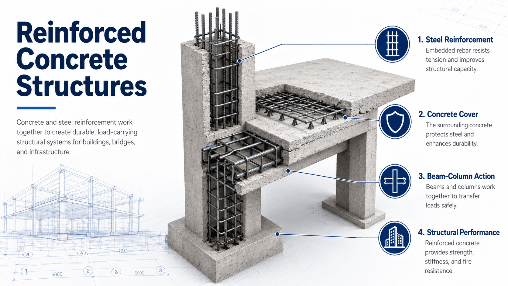
Reinforced concrete structures are load-resisting systems made from concrete and embedded reinforcement, usually steel rebar or welded wire reinforcement. Concrete carries compression well, while reinforcement carries tension, controls cracking, improves ductility, and helps slabs, beams, columns, walls, and foundations work together as a structural system.
How Reinforced Concrete Structures Work
Notice that the important idea is not just “steel inside concrete.” A reinforced concrete structure needs a continuous path for forces to move from slabs into beams, columns or walls, foundations, and finally into the supporting soil.
What is a Reinforced Concrete Structure?
A reinforced concrete structure is a building, bridge, foundation, wall, tank, parking garage, or other structural system made from concrete members that contain reinforcement. The concrete provides stiffness, mass, compressive capacity, fire resistance, and shape. The reinforcement provides tensile strength, crack control, anchorage, ductility, and continuity across joints and supports.
The important structural engineering point is that reinforced concrete is not only a material. It is a system of members and details. A slab may collect floor loads, a beam may transfer those loads to columns, a shear wall may resist lateral force, and a footing may spread load into the ground. Each member only works properly when its reinforcement is placed, developed, and connected to the rest of the load path.
Reinforced concrete design is about placing the right reinforcement in the right location for the forces that actually develop, not simply adding more steel everywhere.
Why Concrete and Steel Work Together
Concrete and steel complement each other because they resist different parts of the internal force system. In a bending member, one side of the section is typically in compression while the opposite side is in tension. Concrete is efficient in compression, but it cracks at relatively low tensile stress. Reinforcement is placed where tensile forces are expected so the member can continue to carry load after cracking.
Compression, tension, and cracking
Cracking does not automatically mean a reinforced concrete member has failed. Controlled cracking is expected in many reinforced concrete members under service loads. The engineering question is whether the crack widths, spacing, deflection, reinforcement stress, corrosion exposure, and load path remain acceptable for the intended structure.
Bond and strain compatibility
Reinforcement must bond to the surrounding concrete so force can transfer between the two materials. Deformed bars, adequate cover, proper development length, hooks, mechanical anchors, confinement, and concrete consolidation all influence whether the steel can develop its intended strength. If bond or anchorage fails, the member may not reach the capacity assumed in design.
At a simplified section level, nominal flexural strength comes from a compression force \(C\) in the concrete, a tension force \(T\) in the reinforcement, and the internal lever arm \(z\) between them. Real design includes strength reduction factors, strain limits, reinforcement limits, shear checks, detailing rules, and code-specific requirements.
Load Path in Reinforced Concrete Structures
Reinforced concrete structures must move loads through a complete path. Gravity loads usually begin at the slab or roof surface, then move through beams, girders, columns, walls, footings, and soil. Lateral loads from wind or earthquakes may move through diaphragms, collectors, moment frames, shear walls, coupling beams, foundations, and ground support.
- Slabs collect floor, roof, occupancy, equipment, snow, and partition loads.
- Beams and girders transfer slab loads to columns, walls, or other supports.
- Columns and walls carry vertical loads and may also participate in lateral resistance.
- Foundations distribute structural demand into soil, rock, piles, or mats.
Load paths can be interrupted by openings, transfer levels, offsets, construction joints, poorly detailed dowels, misplaced embeds, or renovations that cut reinforcement. Engineers trace the force path before trusting isolated member checks.
Main Components of Reinforced Concrete Structures
Reinforced concrete structures are usually made from a combination of horizontal, vertical, and foundation elements. Each component has its own reinforcement layout because each component sees a different mix of bending, shear, axial force, torsion, restraint, temperature movement, and durability exposure.
| Component | Primary structural role | Typical reinforcement concern |
|---|---|---|
| Slabs | Carry floor or roof loads to beams, walls, or columns | Positive and negative bending steel, temperature steel, shrinkage steel, punching shear around columns |
| Beams and girders | Transfer loads across spans and into supports | Bottom steel at midspan, top steel over supports, stirrups for shear, anchorage at ends |
| Columns | Carry axial load and bending from floors and lateral effects | Longitudinal bars, ties, confinement, lap splice location, slenderness effects |
| Shear walls | Resist lateral loads and may carry gravity loads | Boundary reinforcement, vertical and horizontal web steel, coupling beams, foundation anchorage |
| Footings and mats | Spread load into the supporting ground | Flexural steel, punching shear, development at column dowels, cover against soil exposure |
| Retaining walls | Resist lateral soil or fluid pressure | Stem steel on the tension face, footing steel, drainage, sliding, overturning, and soil interaction |
What Controls Reinforced Concrete Design?
Reinforced concrete design is controlled by more than compressive strength. A member with high-strength concrete can still perform poorly if it has insufficient shear reinforcement, poor anchorage, excessive deflection, inadequate cover, rebar congestion, weak construction joints, or poor curing. The controlling issue changes with member type, exposure, span, load pattern, and structural system.
| Control | Why it matters | Engineering implication |
|---|---|---|
| Flexure | Bending creates compression on one side and tension on the other | Reinforcement must be placed where tensile demand develops, with adequate development and continuity |
| Shear | Shear failure can be sudden compared with flexural yielding | Stirrups, ties, slab shear reinforcement, wall detailing, and member depth become critical |
| Serviceability | Structures must limit cracking, deflection, vibration, and long-term deformation | Span-depth ratio, reinforcement ratio, creep, shrinkage, support restraint, and crack control affect usability |
| Durability | Moisture, chlorides, carbonation, freeze-thaw, sulfates, and chemical exposure can reduce service life | Cover, permeability, crack width, drainage, curing, exposure class, and corrosion protection matter |
| Constructability | Dense reinforcement, poor access, and complicated bar geometry can create placement defects | Bar spacing, lap locations, couplers, pour sequence, consolidation, and inspection access must be coordinated |
| Lateral performance | Wind and seismic loads require stiffness, strength, ductility, and continuity | Frames, shear walls, diaphragms, collectors, coupling beams, and boundary elements must work as a system |
Common Reinforced Concrete Structural Systems
Reinforced concrete can be arranged in many structural systems. The best system depends on span, height, architectural layout, lateral demand, fire resistance, construction schedule, material availability, and exposure. A low-rise building, parking garage, bridge deck, high-rise core, and water-retaining structure may all use reinforced concrete, but the governing behavior can be very different.
Cast-in-place concrete frames
Cast-in-place frames are formed, reinforced, poured, and cured on site. They are flexible for irregular layouts, monolithic connections, transfer levels, podium construction, and integrated beams, slabs, walls, and foundations. The tradeoff is schedule dependence on formwork, shoring, curing, inspections, and weather-sensitive field quality.
Flat plates and flat slabs
Flat plate and flat slab systems can reduce floor depth and simplify formwork, but punching shear and deflection often become controlling checks around columns. Drop panels, column capitals, shear studs, thicker slabs, or different framing layouts may be needed when column reactions become large.
Shear wall and core systems
Reinforced concrete shear walls and cores provide lateral stiffness and strength for buildings, especially mid-rise and high-rise structures. Boundary elements, coupling beams, wall openings, collector forces, diaphragm transfer, and foundation anchorage are often more important than a simple wall thickness check.
Precast reinforced concrete systems
Precast systems move much of the fabrication into a controlled plant environment. They can improve speed and quality control, but connections, tolerances, diaphragm behavior, lifting stresses, bearing details, and erection sequencing become major design concerns.
Reinforced Concrete Design Review Checklist
A reinforced concrete review should not stop at member sizing. The engineer needs to check the structure as a system, then confirm that the reinforcement details can actually be built, inspected, and protected over the intended service life.
Define loads and exposure → trace gravity and lateral load paths → select the structural system → size members for strength and serviceability → detail reinforcement for force transfer → check constructability and durability → review drawings for continuity, congestion, cover, joints, and field inspection access.
| Check or decision | What to look for | Why it matters |
|---|---|---|
| Trace the load path | Continuous path from slab to beam, column or wall, foundation, and soil | Strong individual members do not help if forces have no reliable route through the structure |
| Confirm tension zones | Bottom steel at positive moment regions and top steel at negative moment regions | Rebar must be located where tensile stress actually develops |
| Check shear and punching shear | Diagonal shear in beams and walls; local slab failure around columns | Shear-related failures can be brittle and may govern before flexural capacity is reached |
| Review development and splices | Adequate embedment, hooks, couplers, lap lengths, and bar termination locations | Steel cannot provide full strength if it is not properly anchored into the concrete |
| Look for rebar congestion | Tight bars at beam-column joints, walls, transfer girders, mats, and lap zones | Congestion can prevent proper concrete placement and lead to voids, honeycombing, and poor bond |
| Check durability exposure | Cover, crack control, permeability, drainage, chlorides, freeze-thaw, and wet-dry cycles | A member can be strong at opening day but lose service life if corrosion or deterioration is not controlled |
Common Failure Modes in Reinforced Concrete Structures
Reinforced concrete distress can be cosmetic, serviceability-related, durability-related, or structurally serious. The pattern, location, width, timing, and progression of cracking or movement usually matter more than the presence of a crack by itself.
| Failure mode or distress | Typical sign | Why it matters |
|---|---|---|
| Flexural cracking | Vertical cracks in tension zones of beams or slabs | Often expected, but excessive width, growth, or deflection may signal serviceability or strength concerns |
| Shear cracking | Diagonal cracks near supports, openings, or high shear regions | Can indicate a more brittle failure mechanism than flexural yielding |
| Punching shear | Cracking or distress around slab-column connections | Local slab failure around a column can be sudden and serious |
| Column crushing or spalling | Concrete crushing, buckled bars, exposed reinforcement, or loss of cover | Columns are primary gravity elements, so distress requires careful evaluation |
| Corrosion | Rust staining, delamination, cracking along bars, or spalled cover | Corrosion reduces steel area, damages bond, and expands enough to crack surrounding concrete |
| Excessive deflection | Sagging slabs or beams, ponding, cracked finishes, or door/window misalignment | The member may be safe against collapse but still fail serviceability expectations |
Engineering Judgment and Field Reality
Reinforced concrete performance depends heavily on field execution. The design drawings may show the correct bar sizes, spacing, cover, hooks, dowels, lap splices, and construction joints, but the actual structure depends on formwork tolerance, bar placement, chairing, concrete workability, vibration, curing, weather, inspection, and sequencing.
A common field problem is that reinforcement details become too dense to build cleanly. This can happen at beam-column joints, wall boundaries, transfer girders, mats, pile caps, and lap splice zones. When concrete cannot flow around the steel, the result may be honeycombing, voids, poor consolidation, weak bond, and reduced durability.
A reinforced concrete detail should be reviewed from the perspective of the crew placing the bars and concrete. If there is not enough space for aggregate, vibration, inspection, and cover control, the theoretical design may be difficult to execute reliably.
When This Breaks Down
Simplified reinforced concrete explanations break down when they treat the material as if concrete carries all compression, steel carries all tension, and the load path is automatically continuous. Real structures are affected by cracking, creep, shrinkage, restraint, construction tolerances, deterioration, soil movement, lateral drift, temperature change, and staged loading.
- At discontinuities: Openings, offsets, transfer beams, re-entrant corners, and abrupt stiffness changes can concentrate force.
- At joints and splices: Poorly located construction joints, inadequate dowels, or congested lap zones can weaken continuity.
- Under durability exposure: Chlorides, carbonation, freeze-thaw, water intrusion, and chemical exposure can turn small cracks into long-term deterioration paths.
- During construction: Shoring removal, early loading, cold joints, poor curing, and misplaced reinforcement can create demand conditions different from the final design model.
Common Mistakes and Practical Checks
Many reinforced concrete misunderstandings come from focusing on material strength alone. A good concrete strength test does not prove that reinforcement was placed correctly, that development length is adequate, that cover is sufficient, or that the system has a complete load path.
- Assuming more rebar always improves performance: Too much reinforcement can create congestion, poor consolidation, brittle behavior, and difficult field placement.
- Ignoring serviceability: A member can meet strength requirements but still crack or deflect more than the building can tolerate.
- Stopping bars too early: Reinforcement must extend far enough beyond theoretical cutoff points to develop force safely.
- Overlooking cover and exposure: Insufficient cover can accelerate corrosion and reduce fire or durability performance.
- Treating openings as minor: Sleeves, blockouts, embedded items, and penetrations can interrupt reinforcement and local load paths.
Do not evaluate reinforced concrete by compressive strength alone. The structure also depends on reinforcement location, anchorage, shear resistance, crack control, durability, and construction quality.
Relevant Standards and Design References
Reinforced concrete design is normally governed by project-specific codes, local requirements, structural drawings, and adopted design standards. The references below are commonly used in U.S. structural concrete work and help define loads, design requirements, construction execution, and material testing.
- ACI 318: Provides widely used structural concrete building code requirements for strength, serviceability, durability, reinforcement detailing, and member design.
- ACI 301: Covers specifications for structural concrete construction, including materials, execution, tolerances, testing, and quality requirements.
- ASCE/SEI 7: Defines minimum design loads for buildings and other structures, including dead, live, wind, snow, rain, flood, and seismic loads.
- International Building Code: Establishes adopted building code requirements that often reference concrete, load, fire, and structural design standards.
- ASTM concrete and reinforcing steel test standards: Support material testing, sampling, reinforcement properties, and quality control used during design and construction verification.
Frequently Asked Questions
A reinforced concrete structure is a structural system made from concrete and embedded reinforcement, usually steel rebar or welded wire reinforcement. Concrete resists compression well, while reinforcement carries tension, controls cracking, improves ductility, and helps members such as slabs, beams, columns, walls, and foundations act as one load-resisting system.
Steel reinforcement is used because plain concrete is relatively weak in tension and can crack when bending, shrinkage, temperature movement, or restraint creates tensile stress. Reinforcing steel provides tensile capacity, improves crack control, anchors force transfer, and allows reinforced concrete members to behave more predictably under service and strength-level loads.
The main parts are typically slabs, beams, girders, columns, shear walls, footings, mats, grade beams, and sometimes retaining walls or transfer elements. Each part has a different structural role, but they must connect into a continuous load path so gravity and lateral forces can move safely through the building or structure.
Common causes include inadequate reinforcement, poor detailing, insufficient development length, excessive shear or punching shear demand, corrosion, poor concrete consolidation, low cover, construction errors, foundation movement, uncontrolled cracking, and missing load path elements. Failures often come from a combination of design assumptions, field conditions, deterioration, and constructability issues.
Summary and Next Steps
Reinforced concrete structures combine concrete and reinforcement into a complete load-resisting system. Concrete provides compressive strength, stiffness, mass, fire resistance, and formability, while reinforcement provides tensile capacity, crack control, anchorage, continuity, and ductility.
The most important practical ideas are load path, reinforcement placement, bond, development length, shear resistance, serviceability, durability, and constructability. A reinforced concrete structure performs well when the calculations, details, materials, and field execution all support the same structural behavior.
Where to go next
Continue your learning path with related Turn2Engineering resources.
-
Concrete Design
Learn how engineers proportion concrete members and reinforcement for strength, serviceability, durability, and constructability.
-
Concrete Materials
Understand the mixture ingredients and material properties that affect strength, workability, cracking, permeability, and service life.
-
Prestressed Concrete
Compare conventional reinforcement with pre-applied compression used for longer spans, crack control, and deflection performance.