
Key Takeaways
- Core idea: Lightning protection gives lightning current a controlled path from the strike point to earth instead of letting it travel through random building, electrical, or equipment paths.
- Engineering use: Engineers use lightning protection to reduce fire risk, structural damage, equipment damage, service interruptions, and dangerous voltage differences during a strike.
- What controls it: Effective protection depends on air terminal placement, conductor continuity, bonding, grounding, surge protection, soil conditions, layout method, and field changes over time.
- Practical check: A lightning rod alone is not a complete system; missing bonds, corroded clamps, unprotected service lines, and new rooftop equipment can weaken the protection path.
Table of Contents
Introduction
Lightning protection is the engineering practice of giving lightning current a controlled, low-impedance path from a strike point to earth. A complete lightning protection system uses air terminals, conductors, bonding, grounding electrodes, and surge protective devices to reduce fire risk, structural damage, equipment failure, and dangerous voltage differences during a lightning event.
How a Lightning Protection System Works
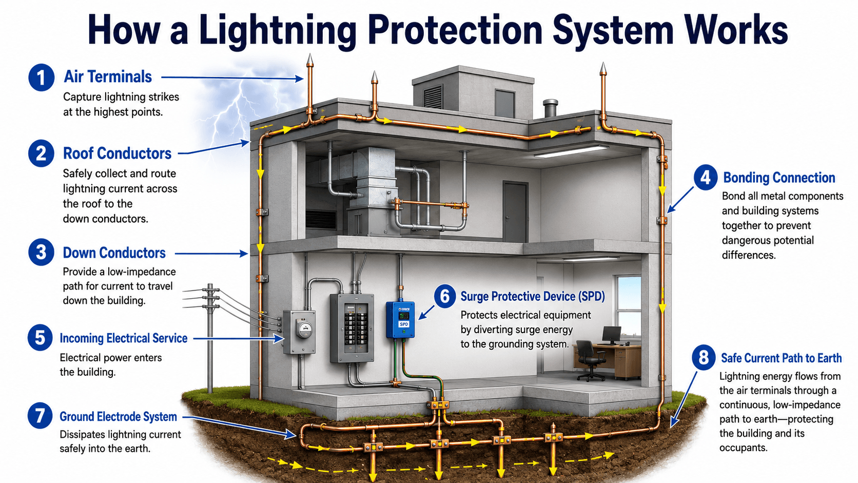
Start at the air terminals on the roof, then follow the conductor path down the structure and into the ground electrode system. The important idea is continuity: every part of the path must stay connected, bonded, and able to carry impulse current safely.
What Is Lightning Protection?
Section focus: Lightning protection is best understood as a complete current-path and bonding system, not just a visible lightning rod on a roof.
Lightning protection is a coordinated system used to reduce damage from direct lightning strikes and nearby lightning-induced surges. In buildings and power systems, the goal is not to stop lightning from occurring. The goal is to manage where the lightning attaches, how the current travels, and how voltage differences are controlled across the structure and electrical systems.
In practical building design, “lightning protection” usually means the complete lightning protection system, not only the visible rods on the roof. The hidden parts—bonding conductors, grounding electrodes, service entrance protection, and inspection access—often control whether the system performs as intended.
Lightning protection is about controlling current path and voltage rise. The safest path is intentional, continuous, bonded, and designed to keep lightning energy away from vulnerable structural and electrical paths.
Lightning Protection System Components
Section focus: A complete lightning protection system depends on strike termination, current routing, bonding, grounding, and surge protection working together.
A lightning protection system is built from several component groups that must work together. Each group has a specific job, but none of them should be evaluated in isolation.
| Component | What it does | Engineering implication |
|---|---|---|
| Air terminals | Provide preferred strike attachment points at roof edges, corners, projections, mechanical equipment, and other exposed locations. | Placement must match the structure geometry and protected zone concept; missing high points can leave vulnerable attachment locations. |
| Roof conductors | Connect strike termination points across the roof and route current toward down conductors. | Sharp bends, poor routing, mechanical damage, and discontinuity can increase impedance and create unwanted flashover paths. |
| Down conductors | Carry lightning current from the roof network toward the grounding system. | Multiple, direct, well-secured paths reduce concentration of current and help control voltage rise along the structure. |
| Bonding connections | Connect metallic systems so they rise in potential together during a strike. | Bonding helps reduce side-flash between conductors, structural steel, conduit, piping, cable trays, and equipment frames. |
| Ground electrode system | Dissipates lightning current into earth through rods, rings, grids, plates, or other electrodes. | Soil resistivity, electrode geometry, corrosion, and bonding to other grounding systems affect performance more than a single resistance number alone. |
| Surge protective devices | Limit transient overvoltages entering through power, communication, control, and data circuits. | SPDs do not replace the external lightning protection system; they protect internal equipment from surge energy and voltage transients. |
For power systems engineering, the bonding and surge protection portions are especially important because lightning does not need to directly hit a device to damage it. A strike to a nearby structure, service entrance, rooftop system, or utility line can still create severe transient voltages.
How Lightning Current Moves Through the System
When lightning attaches to a protected structure, current rises extremely quickly and looks for every available path toward ground. The lightning protection system is intended to make the preferred path obvious: from the air terminal to the roof conductor, down conductor, bonding network, and grounding electrode system.
Strike termination controls the attachment point
Air terminals are placed at exposed points so a strike is more likely to attach to a controlled metallic point than to a roof edge, parapet, mechanical unit, antenna, railing, or unprotected projection. The exact placement method depends on the standard, structure type, risk category, and design approach.
Conductors control the current path
Conductors must route impulse current without unnecessary loops, discontinuities, tight bends, or loose connections. The path should be direct and mechanically reliable because lightning current can exploit small gaps, weak clamps, or unintended parallel paths.
Bonding controls voltage differences
During a strike, different parts of a building can rise to different electrical potentials. Bonding helps keep metallic systems closer in potential so current is less likely to jump across air gaps or through equipment. This is why metal piping, structural steel, electrical grounding systems, cable shields, rooftop equipment, and other conductive systems need to be considered together.
Side-flash is the failure bonding is trying to prevent
Side-flash occurs when lightning current jumps from the intended protection path to another nearby conductive object because the voltage difference becomes large enough to break down the air gap. Bonding reduces that potential difference by tying nearby conductive systems together.
Grounding dissipates current, but it is not magic
Grounding electrodes spread current into the earth, but the surrounding soil still experiences voltage gradients. A low ground resistance value is useful, but it does not by itself prove the lightning protection system is effective. Electrode layout, bonding, conductor geometry, corrosion, and impulse behavior also matter.
Lightning current changes so quickly that conductor geometry matters. Long loops, sharp bends, loose fittings, and separated grounding systems can create high voltage rise even when the system appears electrically connected under normal conditions.
Lightning Protection vs Surge Protection
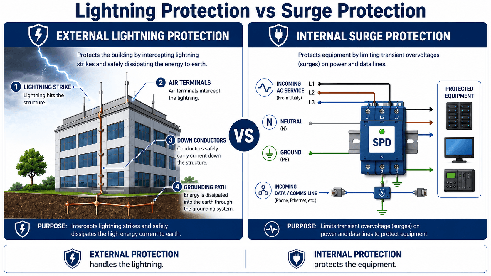
Section focus: External lightning protection handles the direct strike path, while surge protection helps protect equipment connected to power, data, and communication circuits.
Lightning protection and surge protection are related, but they solve different parts of the problem. External lightning protection manages direct-strike current paths. Surge protection limits transient overvoltages on electrical and communication circuits that can damage sensitive equipment.
| Question | External lightning protection | Surge protection |
|---|---|---|
| Primary job | Intercept and route direct lightning current to earth. | Limit transient overvoltage on circuits entering or serving equipment. |
| Main components | Air terminals, roof conductors, down conductors, bonds, and ground electrodes. | Service entrance SPDs, panel-level SPDs, point-of-use SPDs, and data/communication protectors. |
| What it protects | The structure, occupants, building envelope, and controlled current path. | Electrical equipment, electronics, controls, communications, meters, and automation systems. |
| Common mistake | Assuming one rod protects the entire building without a full bonded path. | Assuming an SPD can safely carry direct strike current or replace external protection. |
Why Lightning Protection Matters in Power Systems Engineering
In power systems engineering, lightning protection is part of reliability, safety, and equipment protection. A lightning event can interrupt service, damage switchgear, trip protective devices, destroy controls, degrade insulation, or create dangerous potential differences around grounded equipment.
- Commercial buildings: Lightning protection helps reduce damage to roof systems, electrical service equipment, fire alarm systems, data equipment, and building automation controls.
- Industrial facilities: Bonding and surge protection become more important where cable trays, process piping, motors, control panels, and outdoor equipment are interconnected.
- Solar and renewable sites: Exposed arrays, long cable runs, inverters, combiner boxes, and communications equipment can be vulnerable to direct and induced lightning effects.
- Substations and utility equipment: Grounding, shielding, surge arresters, insulation coordination, and protective device behavior all interact during lightning events.
- Critical facilities: Data centers, communications sites, emergency facilities, and control rooms often require coordinated external protection and layered SPDs.
When a building may need lightning protection
Lightning protection is commonly evaluated for tall or exposed structures, facilities in high-lightning areas, buildings with critical operations, structures with valuable electrical equipment, facilities with flammable or hazardous contents, and projects where downtime or life-safety consequences are high. Owner requirements, insurance requirements, local rules, and risk assessment methods can also drive the decision.
Do not evaluate lightning protection only at the roof. Follow the current path through the building, the bonding network, the grounding system, the service entrance, and the equipment that must keep operating after a storm.
What Controls a Lightning Protection Design?
Section focus: Lightning protection design is controlled by geometry, risk, occupancy, exposure, grounding conditions, service entrances, equipment sensitivity, and maintainability.
Lightning protection design depends on more than building height. The site exposure, structure geometry, occupancy, equipment value, service continuity needs, roof layout, soil conditions, and electrical system configuration all affect the final protection approach.
| Design control | Why it matters | Engineering implication |
|---|---|---|
| Structure geometry | Edges, corners, parapets, towers, rooftop units, and projections influence where lightning may attach. | Air terminal layout must account for the actual roof profile, not only the building footprint. |
| Occupancy and consequence of failure | A warehouse, hospital, data center, fuel storage area, and control building have different risk profiles. | Higher-consequence facilities usually need more careful design review, inspection, and surge coordination. |
| Rooftop equipment | HVAC units, solar equipment, antennas, handrails, and metallic screens may become strike points or side-flash targets. | New roof additions should trigger a protection-zone and bonding review. |
| Electrical service configuration | Incoming power, communications, data, control, and antenna systems can bring surge energy into the building. | SPDs should be coordinated with the service entrance and sensitive downstream equipment. |
| Grounding conditions | Soil resistivity, moisture, corrosion, electrode spacing, and existing grounding systems affect current dissipation. | Grounding should be treated as a network and bonded to other grounding systems where required. |
| Maintenance access | Connections that cannot be inspected are harder to verify over time. | Designers should consider future roof work, clamp access, corrosion exposure, and recordkeeping. |
Common Lightning Protection Layout Methods
Lightning protection layouts are commonly developed using recognized protection-zone concepts. The exact method and dimensions depend on the applicable standard and project requirements, but the design intent is the same: identify likely attachment points and create an intentional strike termination and conductor network.
| Layout method | Basic idea | Where it is commonly useful |
|---|---|---|
| Protection angle method | Uses an assumed protective angle below an air terminal or mast to estimate the protected area. | Useful for simple geometry, conceptual layouts, and easier-to-visualize protection zones. |
| Rolling sphere method | Models possible lightning attachment by imagining a sphere rolling over the structure and touching exposed points. | Useful for complex roofs, exposed equipment, roof projections, and structures where attachment points are less obvious. |
| Mesh method | Uses a conductor network or mesh over roof areas to provide strike termination and current collection paths. | Useful for flat roofs, large roof surfaces, industrial buildings, and structures with broad exposed areas. |
These methods should be treated as design tools, not generic rules of thumb. A layout that appears reasonable on a roof plan can still fail if down conductor routing, bonding, grounding, service entrance protection, or future maintenance access is not addressed.
Lightning Protection Design and Inspection Checklist
Section focus: A useful review follows the lightning path from likely strike points to ground, then checks every location where current could jump, split, enter equipment, or bypass the intended path.
A good lightning protection review follows the energy path from the strike point to earth and then checks every place current could jump, split, enter equipment, or bypass the intended path. The checklist below is a practical way to review a design, inspection report, or existing installation at a high level.
Review the structure from top to bottom: identify likely strike points, verify conductor continuity, check bonding to metallic systems, confirm grounding layout, verify SPDs at service entrances, then inspect field changes such as added rooftop units or modified electrical service equipment.
| Review check | What to look for | Why it matters |
|---|---|---|
| Strike termination coverage | Air terminals located at exposed roof edges, corners, projections, mechanical units, and other likely attachment points. | Unprotected high points can become uncontrolled attachment locations during a strike. |
| Conductor routing | Continuous roof and down conductor paths with secure clamps, gradual bends, and no obvious physical damage. | Discontinuous or high-impedance paths increase the chance of arcing and side-flash. |
| Bonding to metal systems | Connections to structural steel, metallic piping, conduit, cable trays, rooftop equipment, and electrical grounding systems where applicable. | Bonding reduces dangerous voltage differences between nearby conductive systems. |
| Ground electrode network | Accessible, corrosion-resistant ground connections, suitable electrode layout, and bonding to other grounding systems. | The grounding system must dissipate impulse current while limiting uncontrolled potential differences. |
| Surge protection coordination | SPDs at service entrance equipment, distribution panels, data circuits, communication lines, and sensitive loads where needed. | Lightning effects often enter through conductors, not only through the building envelope. |
| Post-installation changes | New HVAC equipment, solar panels, antennas, handrails, cable trays, replacement roof sections, or modified service entrances. | A system that was adequate before a renovation can become incomplete after equipment is added. |
Engineering Judgment and Field Reality
Lightning protection diagrams often show a clean path from roof to earth, but real installations are affected by maintenance, roof work, corrosion, added equipment, missing documentation, and coordination gaps between trades. The system may have been installed correctly years ago and still become compromised after a roof replacement, HVAC upgrade, solar installation, or electrical service modification.
The most important field question is not “Does the building have lightning rods?” It is “Does the building still have a complete, bonded, inspected path that matches the current structure and electrical layout?” That question is especially important for facilities with rooftop equipment, long feeder runs, sensitive controls, or high downtime costs.
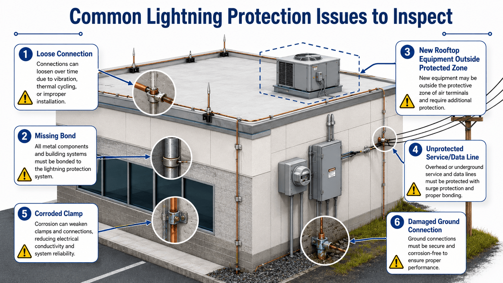
The protection path is only as reliable as its weakest connection. Loose clamps, corrosion, and missing bonds can quietly turn a visible lightning protection system into a system with uncontrolled current paths.
Lightning Protection Inspection and Maintenance Checklist
Inspection and maintenance matter because lightning protection systems are exposed to weather, roof work, mechanical damage, vibration, and corrosion. A system should be reviewed after installation, after major roof or electrical changes, and periodically during facility operation.
| Inspection item | What to check | Why it matters |
|---|---|---|
| Air terminals | Confirm terminals are upright, secure, undamaged, and not blocked by new rooftop equipment. | Damaged or bypassed strike termination points can leave exposed areas unprotected. |
| Roof and down conductors | Look for missing sections, loose supports, sharp bends, broken clamps, or physical damage. | Lightning current needs a continuous and mechanically secure route to earth. |
| Bonding connections | Verify bonds to metallic equipment, structural steel, piping, conduit, cable trays, and grounding systems. | Missing bonds increase side-flash risk and dangerous voltage differences. |
| Ground connections | Inspect visible ground rods, clamps, exothermic welds, conductors, corrosion, and mechanical damage. | Grounding performance depends on the condition and continuity of the earth termination network. |
| Surge protective devices | Check service entrance, panel, data, and communication SPDs, including status indicators where available. | SPDs can degrade or fail after surge events and may need replacement or coordination review. |
| Records and roof changes | Compare drawings and prior inspections against current equipment, roof layout, and service entrances. | Old documentation may not reflect new HVAC units, solar equipment, antennas, or electrical modifications. |
What Lightning Protection Does Not Do
Lightning protection is sometimes misunderstood because the visible parts can make the system look simpler than it is. A well-designed system reduces risk, but it does not eliminate every possible lightning-related hazard.
- It does not prevent storms or stop lightning: It controls the preferred attachment point and current path when a strike occurs.
- It does not eliminate all risk: Lightning is a high-energy natural event, and protection systems reduce risk within the limits of recognized design practice.
- It does not replace surge protection: External conductors and ground electrodes do not protect every circuit from transient overvoltage.
- It does not automatically cover new rooftop equipment: Added HVAC units, solar arrays, antennas, and railings may need additional review.
- It does not remain valid forever without inspection: Corrosion, loose connections, roof work, and service entrance changes can weaken the system over time.
When Lightning Protection Systems Fail
Lightning protection systems fail when the actual strike path differs from the intended path, when conductive systems are not bonded together, or when surge energy enters equipment through unprotected circuits. Many failures are not obvious until a storm exposes them.
- Incomplete current path: Missing conductor sections, disconnected clamps, or damaged down conductors can force lightning current into unintended building paths.
- Poor bonding: Nearby metallic systems at different potentials can produce side-flash, equipment damage, or dangerous touch conditions.
- Uncoordinated surge protection: Power, data, communication, and control circuits can still carry transient voltages into sensitive equipment.
- Roof changes: New HVAC units, solar arrays, antennas, railings, or platforms can sit outside the protected zone unless the system is updated.
- Grounding degradation: Corroded connections, disturbed electrodes, poor soil conditions, and mechanical damage can reduce the effectiveness of the earth termination system.
Common Lightning Protection Mistakes
The most common mistakes come from treating lightning protection as a collection of parts rather than a coordinated system. A design can include recognizable components and still fail if the parts are not placed, connected, bonded, inspected, and maintained correctly.
| Mistake | Why it is a problem | Practical check |
|---|---|---|
| Assuming a lightning rod protects everything | A rod is only the strike termination point; current still needs a safe conductor, bond, and grounding path. | Trace the full path from air terminal to ground electrode and verify bonding along the way. |
| Ignoring rooftop additions | New equipment can become a strike point or sit outside the original protected zone. | Review protection after HVAC, solar, antenna, railing, or roof screen changes. |
| Skipping data and communication lines | Surge energy can enter through low-voltage circuits even when power circuits have SPDs. | Check protection for Ethernet, phone, controls, antennas, monitoring, and communication cables. |
| Leaving metallic systems unbonded | Unbonded metal can create side-flash risk during rapid voltage rise. | Review bonding to piping, conduit, structural steel, cable trays, equipment frames, and grounding systems. |
| Relying on old inspection records | Records may not reflect current roof layout, corrosion condition, or service entrance changes. | Compare drawings and inspection reports against the current installation. |
Do not treat surge protection as a substitute for external lightning protection. SPDs help protect circuits from transient overvoltage, but they are not intended to carry the main direct-strike current path from a building attachment point to earth.
Codes, Standards, and Practical Design References
Lightning protection is a standards-sensitive topic because materials, spacing, bonding, grounding, inspection, and special occupancies can be project-specific. Conceptual learning is useful, but final design and verification should be based on applicable standards, owner requirements, and the authority having jurisdiction.
| Reference | What it helps with | Practical use |
|---|---|---|
| NFPA 780 | Installation requirements and design guidance for lightning protection systems. | Common U.S. reference for buildings, structures, special occupancies, bonding, grounding, and system layout requirements. |
| UL 96A | Inspection and certification context for installed lightning protection systems. | Often used when an owner, insurer, or project specification requires installation verification. |
| IEC 62305 | International lightning protection framework, including risk management and protection concepts. | Useful for international projects or facilities using IEC-based lightning risk and protection zone approaches. |
- Authoritative reference: NFPA 780 lightning protection system guidance explains the purpose of NFPA 780 and how the standard relates to safeguarding people and property from lightning exposure.
- Project-specific criteria: Local codes, owner requirements, insurance requirements, occupancy type, and the authority having jurisdiction can affect the final design and inspection requirements.
- Engineering use: Engineers use standards to confirm component selection, conductor routing, bonding requirements, grounding details, inspection criteria, and whether special structures or hazardous occupancies require additional review.
NFPA 780 and similar references should be treated as design and installation guidance, not as a promise that lightning damage can never occur. Lightning protection reduces risk by controlling current paths within recognized design practice.
Frequently Asked Questions
A lightning protection system provides a preferred path for lightning current to travel from a strike point to earth. It reduces the chance that lightning current will arc through structural steel, electrical systems, rooftop equipment, or occupied spaces.
No. A lightning rod or air terminal is only one part of the system. A complete lightning protection system also needs conductors, bonding connections, grounding electrodes, and coordinated surge protection for incoming power and communication lines.
Lightning protection does not stop storms or guarantee that a structure will never be struck. Its purpose is to control the attachment point and current path so the strike energy is routed safely to ground instead of through uncontrolled paths.
Lightning protection handles the external direct-strike current path using air terminals, conductors, bonding, and grounding. Surge protection limits transient overvoltages on power, data, and communication circuits so sensitive equipment is less likely to be damaged.
Lightning protection should be inspected after installation, after major roof or electrical changes, and periodically during the life of the facility. Rooftop equipment additions, corrosion, loose clamps, missing bonds, and damaged ground connections are common reasons a previously acceptable system can become unreliable.
Summary and Next Steps
Lightning protection is a coordinated system for controlling the path of lightning current from a strike point to earth. A complete approach includes strike termination, conductors, bonding, grounding electrodes, surge protection, inspection, and maintenance.
The engineering value comes from reviewing the whole path. Air terminals must be placed where strikes are likely, conductors must remain continuous, metallic systems must be bonded, SPDs must be coordinated with incoming services, and field changes must be inspected over time.
Where to go next
Continue your learning path with related Turn2Engineering resources.
-
Power Systems Engineering
Build the broader context for how electrical infrastructure is planned, protected, operated, and maintained.
-
Introduction to Power Engineering
Review the foundational concepts behind generation, transmission, distribution, protection, and reliability.
-
Low Voltage Power Systems
Learn how building-level electrical systems, service equipment, distribution panels, and equipment loads fit into practical power design.