Key Takeaways
- Definition: A raft foundation is a large continuous slab, sometimes thickened with beams or pedestals, that supports multiple columns or walls and spreads load over a broad area.
- Use case: Engineers favor rafts when column footings would overlap, soil bearing is moderate to low, or differential settlement control is more important than minimizing foundation footprint.
- Main decision: The core design question is usually not “Can the soil carry the load?” but “How much total and differential settlement will the structure tolerate?”
- Outcome: After reading, you should understand when to use a raft, how to think through the design workflow, and where raft assumptions can become unsafe or misleading.
Table of Contents
Introduction
In brief: Raft foundations are large slab foundations used to distribute building loads over a wide area when isolated footings are inefficient, overlapping, or likely to settle unevenly.
Who it’s for: Students, FE/PE prep, and designers.
For informational purposes only. See Terms and Conditions.
In practice, raft foundation design sits at the intersection of structural stiffness, soil compressibility, groundwater behavior, and constructability. Good design comes from understanding how the slab and the ground work together, not from checking one bearing number alone.
Raft foundations infographic
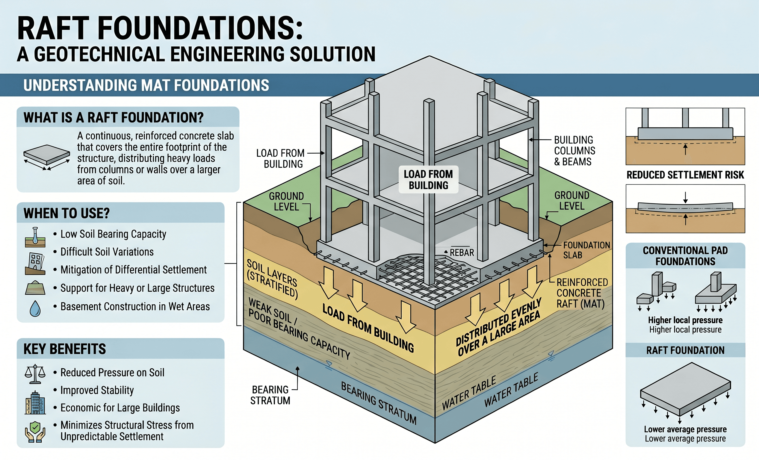
Notice the relationship between column spacing, slab continuity, and the soil reaction below the mat. That interaction is why raft design is usually governed by settlement pattern and stiffness compatibility rather than by a simple shallow footing check alone.
What is a raft foundation?
A raft foundation, also called a mat foundation, is a large continuous reinforced concrete slab placed under all or a major portion of a structure. It supports multiple columns, walls, or cores at once and spreads their combined load across a broad base of soil.
The reason engineers choose a raft is usually practical. If individual spread footings would become so large that they nearly touch or overlap, it often makes more sense to combine them into one foundation system. A raft may also be selected where the soil has limited bearing capacity, where the structure has a dense column layout, or where controlling differential settlement is critical.
From an engineering standpoint, a raft is not just “a bigger footing.” It behaves as a structural slab on elastic or compressible support. That means its stiffness influences the soil pressures beneath it, and the soil stiffness influences the bending, shear, and deflection demands in the slab. The design is therefore a soil-structure interaction problem, even when simplified methods are used.
Core principles, variables, and units
Raft foundations are driven by a few core ideas: distribute load broadly, limit contact stress, reduce differential settlement, and provide enough structural stiffness to bridge local soft spots or irregular loading.
Key variables and typical ranges
The exact values depend on the project, but engineers commonly think in terms of building load intensity, allowable soil bearing pressure, modulus of subgrade response, slab thickness, column spacing, and predicted total and differential settlement. Both SI and US customary units are used in practice, so unit consistency is essential.
- q Contact pressure or bearing pressure; often reported in kPa, psf, or ksf.
- Q Total applied load from the supported structure; may be tracked by column, wall line, or full foundation load combination.
- A Effective raft contact area with the supporting soil, usually in m² or ft².
- k Modulus of subgrade reaction used in Winkler-type idealizations, often in kN/m³ or pci; highly model-dependent.
- s Estimated settlement; engineers watch both total settlement and differential settlement between supports.
- t Raft thickness, controlled by bending, punching shear, stiffness, and construction considerations.
For many rafts, settlement compatibility matters more than maximizing nominal allowable bearing. A “passing” bearing pressure check can still produce unacceptable building movement.
Decision logic and design workflow
Engineers usually arrive at a raft foundation after comparing it against isolated footings, strip footings, and deep foundations. The choice is based on load distribution, settlement performance, column spacing, excavation constraints, and cost.
Start with the column and wall layout. If spread footings become large enough to overlap or leave very little untreated soil between them, a raft becomes a strong candidate. Next, assess bearing capacity and settlement. If bearing is acceptable but settlements are still too large or too uneven, consider a thicker raft, a stiffened raft, a compensated raft, ground improvement, or a piled raft. If loads are very high or compressible deep strata dominate movement, deep foundations may control instead.
A typical workflow begins with geotechnical investigation data, structural load takeoffs, groundwater information, and serviceability criteria. The engineer then develops preliminary raft dimensions, estimates contact pressures, evaluates immediate and consolidation settlement where relevant, and checks the structural slab for bending, punching shear, and local reinforcement demands. After that, the foundation is refined to balance performance, constructability, and cost.
Equations and calculations
The simplest starting point is average contact pressure, which helps frame whether the foundation footprint is broadly reasonable before more advanced analysis begins.
Here, \( q_{avg} \) is the average soil contact pressure, \( Q \) is the total applied service load on the raft, and \( A \) is the gross or effective contact area. This equation is useful early, but it is not the whole story. Real rafts rarely produce uniform pressure because column loads are discrete, slab stiffness is finite, and soil stiffness varies spatially.
Settlement is commonly estimated from elastic, oedometer-based, or layered-soil approaches depending on the soil profile and project stage. For conceptual thinking, the engineer is asking a practical question: how much vertical movement occurs beneath different points on the raft, and will the superstructure tolerate the resulting distortion?
Differential settlement, \( s_{diff} \), is simply the absolute difference in settlement between two points, but its structural consequences can be major. Small differences across short distances can crack partitions, alter door and window function, induce slab distress, and increase force redistribution in the frame above.
Do not rely on a single average bearing pressure equation when column loads are highly irregular, edge loading is severe, or the building core is much stiffer than the surrounding frame.
Worked example
Example
Suppose a building transfers a service load of 24,000 kips to a proposed raft foundation with plan dimensions of 100 ft by 80 ft. The gross contact area is 8,000 ft², so the preliminary average contact pressure is:
If the geotechnical report indicates that service pressures near 3.0 ksf are feasible but settlement sensitivity is moderate, the engineer cannot stop there. The next questions are whether the highest column reactions create local pressure peaks, whether the slab thickness is enough to control punching near heavy columns, and whether the predicted differential movement across the mat remains within the building’s tolerance.
Imagine the initial settlement model predicts 1.1 in. near the building core and 0.5 in. near the perimeter. The total settlement may be manageable, but the 0.6 in. differential movement could still matter depending on span lengths, frame stiffness, cladding sensitivity, and interior finish requirements. The design response may include thickening the raft locally, redistributing stiffness with beams, adjusting column loads through structural coordination, or improving subgrade consistency before placement.
Engineering judgment and field reality
Field conditions often challenge the clean assumptions used in preliminary raft design. Soil profiles are layered, excavation bottoms are disturbed by weather and traffic, groundwater may rise unexpectedly, and fill zones can behave very differently from native material. Even if the report gives one recommended bearing value, the actual foundation response depends on local stiffness contrasts across the entire footprint.
Construction sequencing matters too. If the excavation stays open too long, if subgrade proof-rolling reveals soft pockets, or if wet conditions degrade the founding surface, the built raft may sit on support conditions that differ from the original analysis assumptions. This is one reason experienced engineers pay close attention to subgrade preparation, undercut criteria, blinding concrete, and inspection during excavation.
A raft can hide weak zones better than isolated footings, but it does not eliminate them. Uneven stiffness below the mat often shows up later as differential movement, not as an obvious bearing failure during construction.
Where this method breaks down
Raft foundations are powerful, but they are not universal solutions. The method starts to break down when deep compressible layers control settlement more than near-surface stresses do. In that case, making the foundation larger may reduce contact pressure but do little to stop long-term movement.
Problems also arise when there are very high concentrated loads, substantial uplift, aggressive groundwater conditions, expansive soils, karst features, or severe lateral variability across the building footprint. A raft may still be part of the final answer, but it may need help from piles, drilled shafts, ground improvement, dewatering, or a more sophisticated structural-geotechnical interaction model.
Another common breakdown point is overconfidence in simplified analysis. Methods based on uniform subgrade reaction or idealized pressure blocks can become misleading when the building has a stiff core, large transfer elements, discontinuous load paths, or major basement geometry changes.
Common pitfalls and engineering checks
- Using average bearing pressure as if it proves uniform support under all load combinations.
- Ignoring differential settlement while focusing only on allowable gross pressure.
- Underestimating punching shear demands at heavy columns, walls, or core elements.
- Assuming the reported subgrade modulus is a fixed material constant rather than a modeling simplification.
- Failing to coordinate excavation, dewatering, and subgrade preparation with the geotechnical assumptions used in design.
One of the costliest errors is selecting a raft solely because it lowers average pressure, while overlooking the actual project driver: settlement distortion across the superstructure.
| Parameter | Symbol | Typical units | Notes |
|---|---|---|---|
| Average bearing pressure | q | kPa, psf, ksf | Useful for screening, but not enough for final behavior by itself. |
| Total settlement | s | mm, in. | May be acceptable structurally even when finishes are sensitive. |
| Differential settlement | sdiff | mm, in. | Often controls serviceability and frame distortion. |
| Raft thickness | t | mm, in. | Influences stiffness, bending demand, and punching shear resistance. |
| Subgrade reaction | k | kN/m³, pci | Model input only; depends on footing size, soil type, and interpretation. |
Visualizing raft foundation behavior
A useful mental model is to picture the raft as a flexible or semi-rigid plate resting on springs. Heavy columns push downward, the slab bends between them, and the soil pushes back with a nonuniform reaction. Edges, corners, and stiff building cores often respond differently from the middle of the mat.
That picture helps explain why rafts are rarely designed well from one bearing pressure number alone. The real engineering question is how a continuous slab redistributes load across variable support conditions and whether that redistribution keeps both the soil and the structure within acceptable limits.
When teaching or reviewing raft foundations, a slab-on-springs sketch is often more useful than a generic footing diagram.
Relevant standards and design references
Raft foundation work is guided by both geotechnical and structural references. The exact governing documents depend on jurisdiction, building type, and project delivery standards, but the following are commonly relevant.
- International Building Code (IBC): Establishes the overall regulatory framework for foundation design, geotechnical reporting, and structural safety in many U.S. projects.
- ACI 318: Governs the structural design of reinforced concrete raft slabs, including flexure, shear, punching shear, detailing, and load combinations used in structural design.
- ASCE 7: Provides load criteria that influence service and strength demands transferred into the raft, including gravity, seismic, wind, and load combination requirements.
- Local geotechnical manuals and agency criteria: Often define acceptable bearing pressures, settlement limits, excavation practices, groundwater handling, and subgrade preparation requirements.
- Project-specific geotechnical report: This is the practical source of truth for the founding stratum, settlement concerns, groundwater conditions, and whether shallow support is actually appropriate at the site.
Frequently asked questions
Isolated footings support individual columns or wall segments, while a raft foundation supports many elements together on one continuous slab. Engineers usually prefer a raft when footing sizes begin to overlap, settlement compatibility matters, or the soil is too variable for separate footings to perform consistently.
In many real projects, differential settlement and slab stiffness control before gross bearing failure does. Punching shear near heavy columns, groundwater conditions, and construction quality can also become the real controlling issues.
A raft becomes less effective when deep compressible soils dominate settlement, load concentrations are extreme, or site conditions create uplift, expansive behavior, or severe variability. In those cases, the engineer may need ground improvement, a piled raft, or a full deep foundation system.
Raft foundations are common under buildings with dense column grids, basements, podiums, tanks, cores, and structures on soils where individual footings would be too large or settle too unevenly. They are also used where construction simplicity and broad load distribution offer better value than many separate shallow foundations.
Summary and next steps
Raft foundations are shallow foundation systems designed to spread many structural loads over one continuous base. They are especially useful when isolated footings overlap, when subgrade support is moderate rather than strong, or when the real problem is settlement compatibility across the structure.
The best raft foundation designs balance geotechnical behavior and structural response. Engineers must think about more than bearing pressure: slab stiffness, subgrade variability, punching shear, groundwater, and differential settlement often decide whether the system performs well over time.
As you study raft foundations, focus on the design logic behind the choice. Ask what drives the decision, what assumptions are built into the analysis, and what field conditions could invalidate those assumptions before construction is complete.
Where to go next
Continue your learning path with these related geotechnical topics.
-
Read a deeper dive on shallow foundations
Useful for comparing raft foundations to spread footings, strip footings, and other near-surface support systems.
-
Study pile foundations
A good next step when shallow support may not be enough and deeper load transfer becomes necessary.
-
Review foundation design principles
Helps connect bearing, settlement, structural demand, and constructability into one broader design workflow.