Key Takeaways
- Core idea: Disconnectors are mechanical switching devices used to isolate power-system equipment with a visible open point.
- Engineering use: They are used around lines, transformers, busbars, breakers, and maintenance zones so crews can verify isolation before work begins.
- What controls it: Proper application depends on voltage class, continuous current, short-time withstand current, insulation level, switching duty, mechanical operation, and interlocking.
- Practical check: A typical disconnector is not a fault-interrupting device and should not be opened under load unless it is specifically rated for that duty.
Table of Contents
Introduction
Disconnectors in power systems are mechanical switching devices used to isolate circuits, lines, transformers, bus sections, or other equipment from an energized source. Their most important job is to create a visible isolation point for maintenance and inspection after current has been interrupted by the proper switching or protective device. Think of a disconnector as the device that proves separation, not the device that clears the electrical problem.
How Disconnectors Fit in a Substation Bay
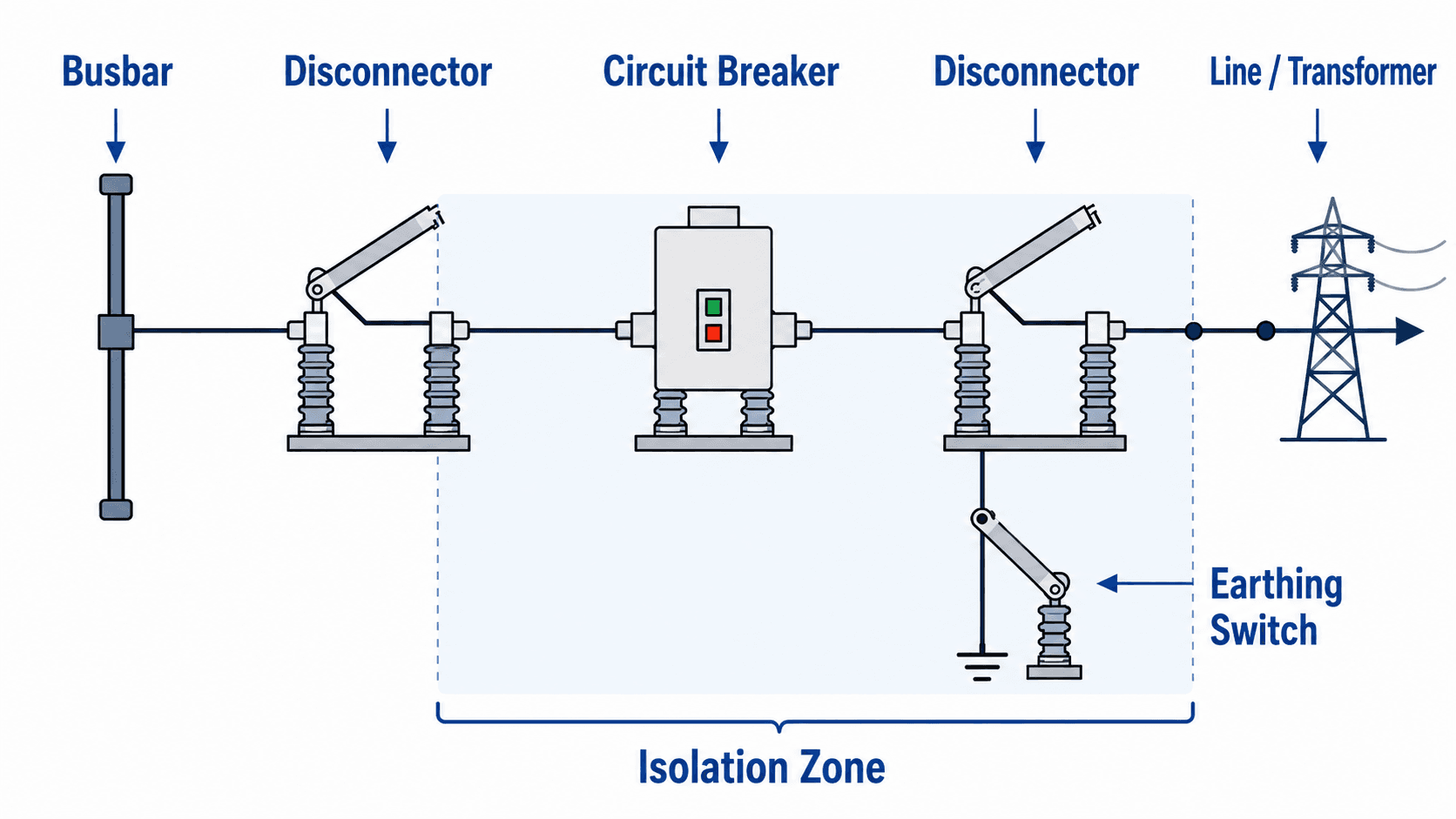
Notice that the disconnectors are not shown as the devices clearing current. The breaker handles interruption, while the disconnectors establish the open isolation points used for safe access and maintenance control.
What Is a Disconnector in a Power System?
A disconnector, also called a disconnect switch or isolator in many contexts, is a mechanical device that opens a circuit by physically separating conductive contacts. In high-voltage substations, this open gap is valuable because it gives operators and maintenance crews a visible indication that a section of equipment has been isolated from the source.
The important distinction is that isolation is not the same as protection. A disconnector is normally not intended to detect faults, trip automatically, or interrupt high fault current. It is part of the switching and isolation arrangement around protected equipment, but the protective action is usually performed by relays, fuses, or circuit breakers.
A circuit breaker interrupts current. A disconnector proves isolation. Confusing those two roles is one of the most important mistakes to avoid when reading one-line diagrams or reviewing switching procedures.
Disconnector vs Isolator vs Switch-Disconnector
The terms disconnector, isolator, disconnect switch, and switch-disconnector are sometimes used loosely, but they are not always interchangeable. The exact meaning depends on the voltage class, equipment standard, manufacturer rating, and utility operating practice.
| Term | Typical meaning | Important caution |
|---|---|---|
| Disconnector | Mechanical device used to isolate equipment by creating an open contact gap | Normally treated as off-load unless the rating specifically states otherwise |
| Isolator | Common synonym for a disconnector, especially in substation and switchgear discussions | Do not assume interrupting capability from the word isolator alone |
| Disconnect switch | General term used across low-, medium-, and high-voltage equipment | Can describe many devices, so rating and duty must be checked |
| Switch-disconnector | Device assigned both switching and isolating duties within its rating | May be able to make or break specified currents, but only within its published duty |
| Load-break switch | Switch designed to interrupt normal load current | Not the same as a fault-interrupting circuit breaker unless combined with appropriate protection |
Some disconnectors may be rated for specific make or break duties such as bus-transfer current, line charging current, transformer magnetizing current, or grounding-switch duty. Those are rating-specific applications and should not be assumed from the word “disconnector” alone.
How Disconnectors Work
A disconnector works by moving a blade, contact arm, pantograph, or other conductive member away from a fixed contact. In an air-insulated substation, this creates a physical air gap that can be seen from the ground or verified by position indication. In gas-insulated switchgear, the same function exists inside an enclosed assembly, although visual confirmation may rely on mechanical indicators and approved operating procedures.
The visible isolation gap
The visible gap is the main reason disconnectors remain important even in automated substations. When a breaker opens, its contacts are usually enclosed inside a tank, interrupter, or switchgear compartment. A disconnector provides a clearer isolation point in the circuit layout, helping define the safe work boundary after switching, verification, grounding, and lockout/tagout steps are complete.
Manual and motor-operated disconnectors
Smaller or simpler installations may use manual operating handles, while substations often use motor-operated mechanisms that can be controlled locally or remotely. Either arrangement still depends on correct interlocking, blade travel, contact alignment, auxiliary contacts, and operating sequence.
Air-insulated and gas-insulated applications
Air-insulated switchyards commonly use open-air disconnectors mounted on porcelain or composite insulators. Gas-insulated switchgear uses enclosed disconnectors where space is limited or environmental control is important. The engineering goal is the same in both cases: define and control an isolated section of the power system.
Where Disconnectors Are Used in Substations
Disconnectors are used wherever a power-system element may need to be isolated for maintenance, inspection, testing, repair, or switching configuration changes. In substations, the disconnector location is usually chosen to define a safe work boundary around a specific bay, circuit, or item of equipment.
| Application | What the disconnector isolates | Why engineers use it there |
|---|---|---|
| Line bay | Transmission or distribution line terminals | Allows a line section to be isolated after breakers interrupt current and switching procedures are complete |
| Transformer bay | Transformer high-voltage or low-voltage terminals | Creates isolation points for transformer inspection, testing, oil work, bushing replacement, or protection maintenance |
| Breaker bay | Both sides of a circuit breaker | Lets crews work on the breaker after the surrounding disconnectors define the isolated section |
| Busbar section | Bus segments, bus couplers, or transfer bus arrangements | Supports switching flexibility and maintenance without necessarily de-energizing the entire substation |
| Capacitor or reactor bay | Reactive power equipment and associated switching equipment | Provides isolation for banks that may also require discharge, grounding, and special operating checks |
| Renewable plant substation | Collector feeders, generator step-up transformers, and grid interconnection equipment | Supports isolation of plant equipment while coordinating with utility switching orders and interconnection requirements |
On a one-line diagram, verify whether the disconnector location actually isolates the equipment being worked on. A visible open point on the wrong side of a transformer, breaker, or bus tie may not create the intended work boundary.
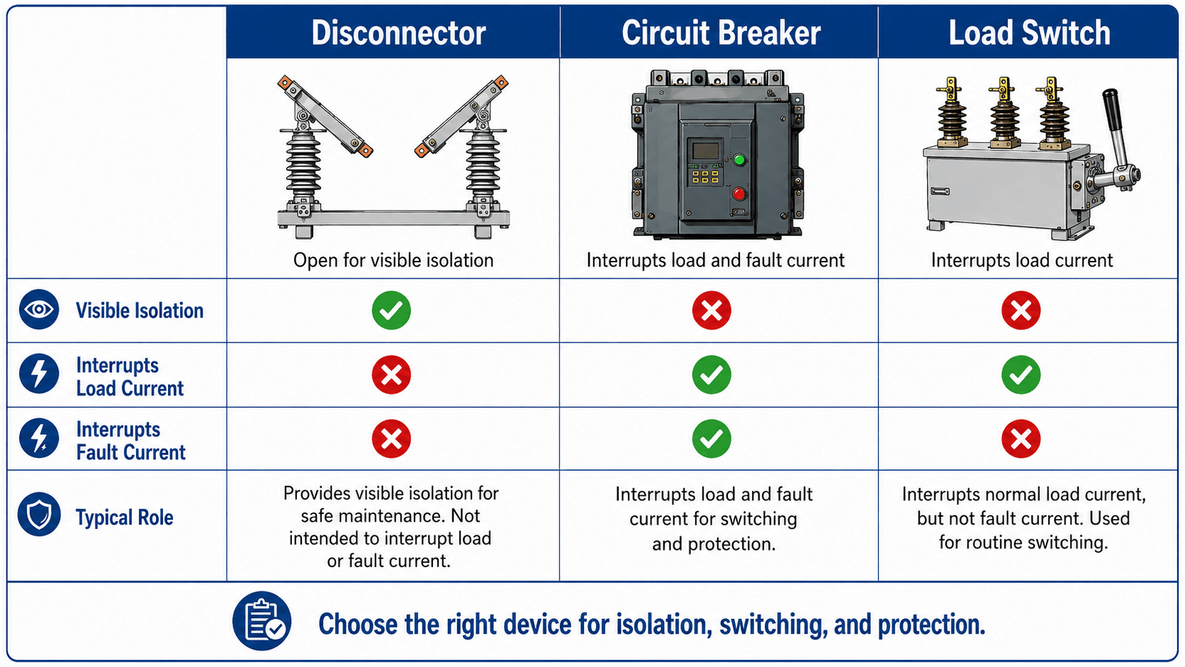
Disconnector vs Circuit Breaker vs Load Switch
Searchers often mix up disconnectors, circuit breakers, and load switches because all three can appear in switching equipment. The difference is not whether the device has contacts; the difference is what current it is designed to interrupt and what role it plays in the switching sequence.
| Device | Main purpose | Typical current-interrupting role | Common engineering use |
|---|---|---|---|
| Disconnector | Visible isolation | Usually off-load only unless specifically rated otherwise | Isolating lines, transformers, breakers, bus sections, and maintenance zones |
| Circuit breaker | Switching and protection | Interrupts load current and fault current within its rating | Clearing faults, switching circuits, and responding to protective relay trip commands |
| Load switch | Routine load switching | Interrupts normal load current, but not high fault current unless paired with other protection | Switching feeders, ring-main units, and distribution circuits under normal conditions |
| Earthing switch | Grounding isolated equipment | Not used as a normal load-interrupting device | Connecting an isolated section to ground after proper isolation steps |
Some metal-clad switchgear and withdrawable breaker arrangements provide an isolation position, but that does not make every breaker a visible-open disconnector. Always check the specific equipment construction, nameplate, interlocking scheme, and operating procedure.
Can a Disconnector Open Under Load?
A plain disconnector should generally not be opened under load. If current is flowing and the contacts separate without a suitable interrupter, an arc can form across the gap. At medium and high voltage, that arc can damage equipment, endanger personnel, and create a switching event far more severe than the operator expected.
Some equipment is specifically designed as a switch-disconnector, load-break switch, or interrupter-equipped disconnecting device. Those terms matter because they indicate a different operating duty than a basic off-load isolating disconnector. Engineers and operators should always check the equipment nameplate, drawings, procedures, and applicable ratings before assuming a device can interrupt current.
| Current or duty | Why it matters | Practical interpretation |
|---|---|---|
| Load current | Normal operating current can sustain an arc if interrupted by the wrong device | Use a breaker, load switch, or properly rated switch-disconnector before opening an off-load disconnector |
| Fault current | Fault current can be many times normal load current | Fault interruption is a breaker, fuse, or protection-system function, not a plain disconnector function |
| Charging current | Long lines, cables, or bus sections can have capacitive charging current | Do not assume “light load” means no switching duty; check the applicable equipment rating |
| Transformer magnetizing current | Energized transformers may draw magnetizing current even when secondary load is disconnected | Transformer switching duties require rating-specific review |
| Induced current or trapped charge | Nearby energized circuits or stored charge can create hazardous voltage after isolation | Verification, grounding, and approved switching steps remain important after the disconnector is open |
The usual sequence is to interrupt current first with a breaker or load-interrupting device, then open the disconnector to create the visible isolation point.
Main Types of Disconnectors
Disconnector geometry is selected around voltage level, bay layout, phase spacing, available clearance, mechanical loading, environmental exposure, and operating method. The names describe how the moving contact creates the open gap.
| Disconnector type | How it opens | Where it is useful | Engineering consideration |
|---|---|---|---|
| Center-break | Two arms separate near the center of the span | Outdoor air-insulated substations with enough horizontal clearance | Simple visual gap, but requires space for blade swing and phase spacing |
| Double-break | A moving center section opens at two contact points | Higher-current or higher-voltage layouts where balanced geometry is preferred | More contacts and moving parts require careful alignment and maintenance |
| Vertical-break | The blade rotates upward or downward to create the gap | Substations where horizontal footprint is limited | Clearance above the switch and mechanical wind or ice loading can be important |
| Pantograph | A linkage rises or folds to connect to an overhead bus | Compact or high-voltage yards with overhead bus arrangements | Requires precise mechanical travel and contact pressure at the bus connection |
| GIS disconnector | Contacts move inside an enclosed gas-insulated compartment | Urban, indoor, offshore, or space-constrained substations | Operators depend on approved position indication and interlocking rather than a visible open-air blade |
Safe Disconnector Operating Sequence
The most practical way to understand disconnectors is to think in sequence. The disconnector is normally not the first device operated when a circuit is carrying current. It becomes useful after the circuit has been interrupted and verified, because it establishes the isolation point for the equipment being worked on.
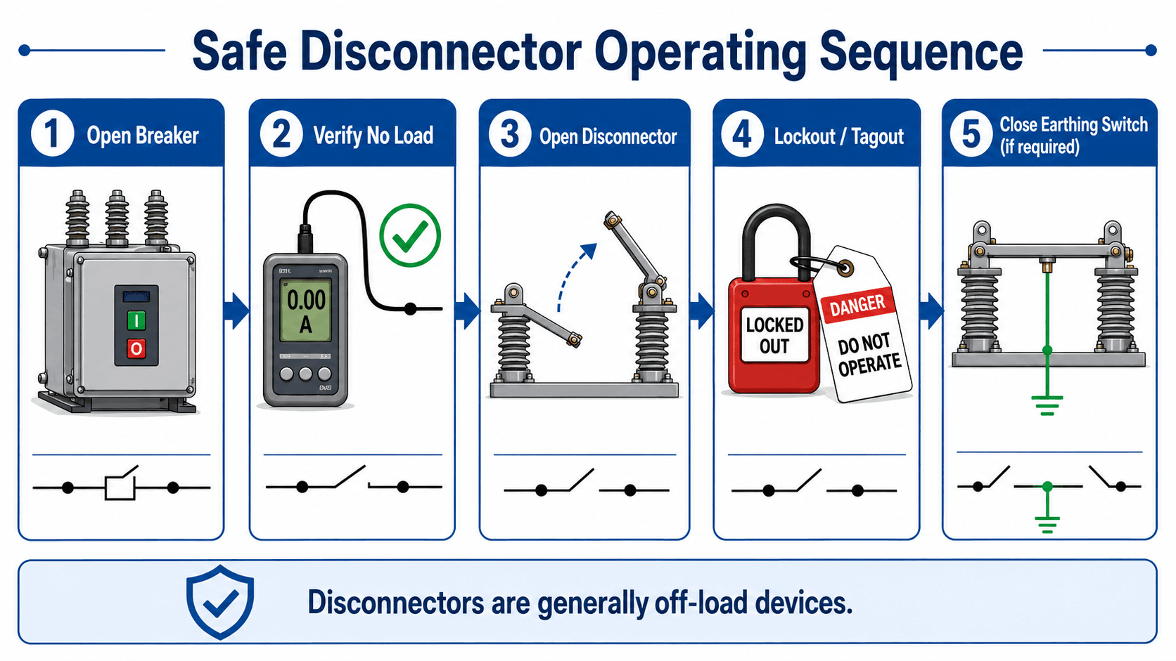
Identify the equipment to isolate → open the circuit breaker or approved load-interrupting device → verify no load or approved switching condition → open the disconnector → apply lockout/tagout → close the earthing switch if the switching order requires grounding.
| Switching check | What to look for | Why it matters |
|---|---|---|
| Breaker status | The breaker or approved load-interrupting device has opened and indication agrees with the switching order | The disconnector should not be asked to interrupt current it is not rated to interrupt |
| Isolation boundary | The open disconnectors define the exact bay, line, transformer, or bus section being isolated | Crews need a clear work boundary, not just a general assumption that equipment is de-energized |
| Interlocks | Mechanical, electrical, or control interlocks prevent unsafe combinations of breaker, disconnector, and earthing switch positions | Interlocks reduce the chance of closing a ground onto an energized circuit or opening an isolator under load |
| Grounding state | The earthing switch is closed only after the section is isolated and the procedure requires grounding | Grounding helps control induced voltage, trapped charge, and accidental energization risk |
Ratings Engineers Check Before Applying Disconnectors
Disconnectors may look mechanically simple, but they are still rated power-system equipment. A disconnector that is acceptable in one bay may be unsuitable in another if the voltage, current, insulation, withstand, switching duty, or environmental exposure changes.
| Rating or check | Why it matters | Engineering implication |
|---|---|---|
| Rated voltage and insulation level | The open gap and support insulation must withstand system voltage and transient overvoltages | Clearances, basic insulation level, and substation insulation coordination must be reviewed together |
| Continuous current rating | Closed contacts carry normal operating current without overheating | High load current, solar or wind export, transformer loading, and seasonal ratings can affect suitability |
| Short-time withstand current | The closed device may need to withstand fault current until breakers clear the fault | The disconnector is not interrupting the fault, but it must survive electromechanical and thermal stress while closed |
| Assigned switching duty | Some devices may have specific ratings for making or breaking defined currents | Do not treat a switch-disconnector, load-break switch, and plain disconnector as equivalent |
| Mechanical endurance | Contacts, hinges, bearings, linkages, and motor operators wear over repeated operation | Frequently operated sectionalizing points need more attention than rarely operated isolation switches |
| Environmental exposure | Ice, wind, salt, dust, pollution, wildlife, and corrosion affect contact performance and mechanical movement | Outdoor substations may require heaters, coatings, creepage review, washing practices, or more frequent inspection |
Disconnector Failure Modes and Inspection Checks
A disconnector can pass current in normal operation for years and still become a weak point if the contacts loosen, blade travel changes, or outdoor conditions degrade the hardware. Inspection should focus on whether the device can fully open, fully close, carry current without overheating, and report its position correctly.
| Failure mode | Field symptom | Engineering concern | Practical check |
|---|---|---|---|
| Poor contact pressure | Hot spot, discoloration, pitting, or abnormal infrared scan | High-resistance heating can damage contacts and reduce current-carrying capability | Inspect contact wipe, jaw condition, fasteners, and thermal history |
| Incomplete blade travel | Blade not fully seated or not fully separated | Closed position may overheat; open position may not provide the intended isolation boundary | Verify physical travel, stops, linkages, limit switches, and position indication |
| Corrosion or contamination | Stiff operation, tracking marks, rust, salt buildup, or polluted insulators | Mechanical failure, insulation stress, and poor contact performance become more likely | Review cleaning, lubrication, creepage, hardware condition, and environmental exposure |
| Motor-operator failure | Remote command fails, stalls, or stops short of final position | Switching sequence may be delayed or position may be uncertain | Test local and remote operation, auxiliary contacts, controls, power supply, and manual backup |
| Interlock failure | Unsafe combinations are possible or blocking logic does not work | Personnel and equipment can be exposed to incorrect switching states | Functionally test mechanical, electrical, and control interlocks during maintenance windows |
Engineering Judgment and Field Reality
On a one-line diagram, a disconnector is only a simple switch symbol. In the field, it is a mechanical assembly exposed to alignment issues, contact wear, weather, operating linkage tolerance, auxiliary switch errors, and human-factor risk. A switch may appear open from one angle but still require confirmation through the approved indication, tagging, and operating procedure.
Experienced engineers and operators pay close attention to blade seating, contact wipe, jaw engagement, hot spots, arcing marks, motor-operator travel, and whether position indication matches the actual physical position. A disconnector that does not fully close can become a high-resistance heating point. A disconnector that does not fully open can compromise the isolation boundary.
The visible gap is powerful, but it is not the entire safety system. Safe work also depends on switching orders, verification, grounding, interlocks, lockout/tagout, operating authority, and clear communication between control room and field crews.
When the Simplified Disconnector Model Breaks Down
A simple explanation says “a disconnector isolates equipment,” but real systems create edge cases. The simplified model breaks down when the device is being treated as if it can interrupt current, when position indication is trusted without procedural verification, or when the installation conditions no longer match the rating assumptions.
- Charging current and induced voltage: Long lines, cables, and nearby energized circuits can create voltage or small currents that still matter during switching and grounding.
- Wrong device duty: A switch-disconnector, load-break switch, grounding switch, and plain disconnector can have different ratings even when their names sound similar.
- Mechanical misalignment: Blade travel, contact pressure, and jaw engagement can drift over time, especially in outdoor equipment exposed to wind, ice, corrosion, or foundation movement.
- Control indication mismatch: Auxiliary contacts may indicate a position that does not perfectly represent the physical blade or contact condition.
Common Mistakes and Practical Checks
Most disconnector mistakes come from confusing isolation, switching, and protection. A technically correct drawing can still be misunderstood if the reader assumes every switch symbol can interrupt load or fault current.
- Calling every isolating device a breaker: A breaker interrupts current; a disconnector establishes isolation after the proper interruption step.
- Ignoring the earthing switch state: The isolated section may still need grounding before maintenance begins, depending on the switching order and system conditions.
- Forgetting withstand duty: A closed disconnector may carry fault current briefly until breakers clear, so short-time withstand rating still matters.
- Overlooking environmental duty: Outdoor disconnectors can suffer from contamination, corrosion, ice, poor lubrication, loose hardware, or incomplete travel.
- Assuming “open” always means “safe to work”: The open disconnector is only one part of the safe-work boundary; verification, grounding, tagging, and operating authority still matter.
Never assume a disconnector can open a live circuit just because it appears in a switching lineup. Confirm the device rating and the approved operating procedure.
Standards, Manuals, and Design References
Disconnector application is normally governed by utility standards, owner requirements, project specifications, equipment ratings, and the applicable high-voltage switchgear standards used for the project. Standards do not replace the switching order, but they help define ratings, construction requirements, testing, and equipment application limits.
- IEEE C37.30.1-2022: IEEE requirements for AC high-voltage air switches rated above 1000 V cover ratings, construction requirements, design test requirements, applications, and suggested practices for high-voltage switches including disconnecting and grounding switch applications.
- Project-specific criteria: Utility operating practices, substation standards, equipment manuals, and site switching orders usually control the final operating sequence.
- Engineering use: Engineers use these references to check voltage class, continuous current, short-time withstand, insulation requirements, mechanical operation, and whether a device is suitable for its intended duty.
Frequently Asked Questions
A disconnector is a mechanical switching device used to isolate a circuit, line, transformer, bus section, or other equipment from an energized source. In high-voltage power systems, its main purpose is visible isolation for maintenance and inspection, not automatic fault protection.
No. A circuit breaker is designed to interrupt load current and fault current, while a typical disconnector is used after current has already been interrupted. The disconnector creates a visible open point so equipment can be safely isolated for work.
A plain disconnector should generally not be opened under load unless the equipment is specifically rated for that duty. Opening an off-load disconnector while current is flowing can create dangerous arcing, equipment damage, and serious safety hazards.
A plain disconnector is mainly an off-load isolation device, while a switch-disconnector is assigned a switching duty and may be rated to make or break specified currents. The exact capability depends on the equipment standard, nameplate, and manufacturer rating.
Earthing switches are used after isolation to connect the isolated section to ground when required by the switching procedure. This helps control induced voltage, trapped charge, and accidental re-energization risk during maintenance.
Summary and Next Steps
Disconnectors are isolation devices used to create a physical separation in power-system circuits. Their value is not that they replace breakers, fuses, or protective relays, but that they help define a visible and controllable maintenance boundary.
The most important practical concepts are device duty, switching sequence, visible isolation, earthing switch coordination, interlocking, equipment ratings, inspection condition, and field verification. A well-applied disconnector is part of a safe switching system, not a standalone protection device.
Where to go next
Continue your learning path with related Turn2Engineering resources.
-
Switchgear
Learn how breakers, busbars, relays, controls, and isolation devices work together inside power-system switching assemblies.
-
Transmission Line Protection
Learn how relays and breakers identify and clear faults on transmission circuits before isolation steps are applied.
-
Overcurrent Protection
Review how protective devices respond to overloads and short circuits, which is a different role than visible isolation.