Key Takeaways
- Definition: A triaxial test loads a cylindrical soil specimen under controlled confinement to measure shear strength under realistic drainage and stress conditions.
- Use case: Engineers use it when they need strength parameters for slopes, retaining systems, embankments, excavations, and foundation problems.
- Main decision: The most important choice is whether the design problem is short-term or long-term, drained or undrained, and total-stress or effective-stress controlled.
- Outcome: After reading, you should be able to interpret UU, CU, and CD test logic and understand what the reported \(c\), \(\phi\), \(s_u\), and pore-pressure data really mean.
Table of Contents
Introduction
In brief: The triaxial test measures soil shear strength by loading a confined specimen so engineers can estimate strength under field-like stress and drainage conditions.
Who it’s for: Students, FE/PE prep, and practicing geotechnical engineers.
It is one of the most useful soil tests because it can represent both short-term undrained behavior and long-term effective-stress behavior instead of forcing one simplified failure condition.
Triaxial Test infographic
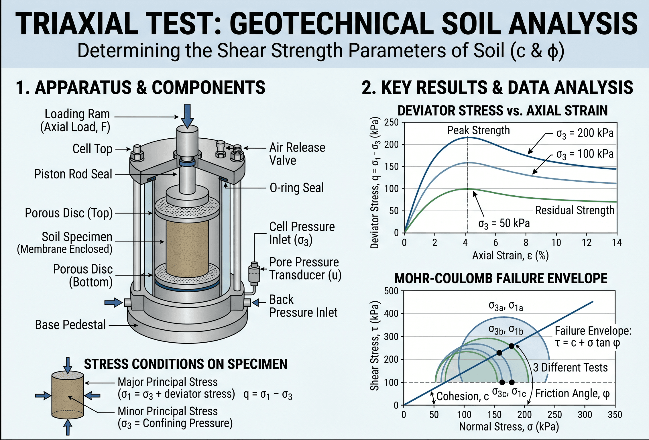
Start by noticing the difference between the confining pressure \(\sigma_3\) applied around the specimen and the axial loading that produces the deviator stress \(q\). Then look at how multiple tests at different confining pressures create a failure envelope used to estimate cohesion and friction angle.
What is a triaxial test?
A triaxial test is a laboratory soil test in which a cylindrical specimen is enclosed in a rubber membrane, subjected to an all-around cell pressure, and then loaded axially until a target strain level or failure condition is reached. The test is called “triaxial” because the sample experiences three principal stresses, even though most routine lab interpretation focuses on the major principal stress \(\sigma_1\) and minor principal stress \(\sigma_3\).
In practical geotechnical work, the value of the triaxial test is control. Unlike simpler tests that force a failure plane or provide limited drainage control, the triaxial apparatus lets the engineer define confinement, drainage condition, consolidation stage, and often pore-pressure measurement. That makes it one of the best tools for estimating how soils actually gain or lose strength in the field.
The results are commonly used to estimate undrained shear strength for short-term loading problems, or effective stress parameters \(c’\) and \(\phi’\) for long-term stability and deformation problems. When paired with a good geotechnical investigation and sound soil mechanics judgment, the triaxial test becomes far more than a lab exercise. It becomes a design input.
Core principles, variables, and units
The triaxial test is built around stress state, drainage, and strain response. A confining pressure is applied around the specimen, then the sample is loaded axially. Depending on the test type, drainage may be prevented or allowed, and pore pressure may or may not be measured. The resulting stress-strain behavior tells the engineer how the soil mobilizes strength.
Key variables and typical ranges
Most reporting focuses on cell pressure, deviator stress, axial strain, pore pressure, and the final strength parameters. Typical ranges depend on soil type and project scale, but the important habit is not memorizing one number. It is checking whether the chosen stress range actually resembles the field problem being modeled.
- \(\sigma_3\) Minor principal stress or confining pressure; commonly reported in kPa or psi.
- \(\sigma_1\) Major principal stress at the axial loading condition; reported in kPa or psi.
- \(q\) Deviator stress, usually \(q = \sigma_1 – \sigma_3\); often the clearest indicator of mobilized strength.
- \(\varepsilon_a\) Axial strain, usually reported as percent strain; common failure reporting may use a peak value or a strain cutoff such as 15%.
- \(u\) Pore-water pressure, measured in CU tests with pore-pressure monitoring when effective-stress interpretation is needed.
- \(c’, \phi’\) Effective cohesion intercept and effective friction angle used for long-term design in many soils.
- \(s_u\) Undrained shear strength, commonly used for saturated clays under short-term loading.
Do not choose triaxial confining pressures just because they are convenient lab numbers. Choose them because they bracket the effective stresses expected in the field.
A quick sanity check helps. If a shallow excavation, embankment stage, or slope problem is being analyzed at relatively low effective stress, a very high laboratory confinement may distort the interpretation. Likewise, if a deep foundation zone is being modeled, low confining pressures may under-represent the actual stress path. Good data starts with realistic specimen selection and realistic testing stress levels.
Decision logic or design workflow
The most important engineering choice is not whether a triaxial test is “better” than another test in the abstract. It is whether the procedure matches the loading and drainage condition of the project problem.
Step 1: Define the design question. Are you checking short-term construction stability, long-term slope behavior, excavation support, or settlement-related strength behavior?
Step 2: Decide whether total stress or effective stress controls the problem. Saturated clay under rapid loading often points toward undrained behavior. Long-term performance usually points toward effective stress behavior.
Step 3: Match the lab procedure to field drainage. Use UU for rapid total-stress response, CU when consolidation should occur before shearing and pore pressure is needed, and CD when drainage during shearing must be represented.
Step 4: Select representative specimens and stress ranges. Disturbance, anisotropy, fissures, and structure matter as much as the machine settings.
Step 5: Check whether the reported parameters make geologic sense before using them in design.
How UU, CU, and CD differ
In an Unconsolidated Undrained (UU) test, the sample is not consolidated under the cell pressure and no drainage is allowed during shearing. This is typically used for short-term total-stress interpretation in saturated fine-grained soils. It is fast, but it does not provide direct effective-stress strength unless additional assumptions are made.
In a Consolidated Undrained (CU) test, the specimen is first allowed to consolidate under the applied cell pressure, then sheared without drainage. If pore pressures are measured, the engineer can back out effective stresses and obtain effective-stress parameters. This is one of the most informative triaxial procedures because it gives both stress-strain behavior and pore-pressure response.
In a Consolidated Drained (CD) test, the specimen is allowed to consolidate and also allowed to drain during shearing. It is slower, especially for low-permeability soils, but it is often the preferred route for long-term drained strength interpretation.
Equations and calculations
Triaxial testing is not just about reading a peak load from a machine. The core calculations connect measured load, specimen geometry, pore pressure, and Mohr-Coulomb strength interpretation.
The first equation defines deviator stress. The second shows how total stresses are converted to effective stresses when pore pressure is known. The third is the Mohr-Coulomb failure relationship used to interpret shear strength along a failure envelope.
What each term means in practice
The measured axial load is converted into axial stress using the corrected specimen area. That correction matters because the area changes as the sample shortens. Cell pressure provides the confining stress. If pore pressure is measured, effective stresses can be computed directly. Multiple tests at different confining pressures are then used to define the failure envelope and estimate \(c’\) and \(\phi’\).
When strength parameters change sharply from one confining pressure to another, do not jump straight to curve fitting. First ask whether specimen disturbance, saturation quality, or a change in soil fabric is affecting the data.
For saturated clays in total-stress analysis, engineers often use the UU or undrained interpretation in simplified form:
This shortcut is useful, but only when the test procedure and soil type justify it. Using \(q_f / 2\) blindly on soils with partial drainage, sample disturbance, or unusual structure is a common source of design error.
Worked example
Example
Suppose a saturated clay specimen is tested in a CU triaxial test with pore-pressure measurement. The cell pressure is \( \sigma_3 = 150 \, \text{kPa} \). At failure, the total major principal stress is \( \sigma_1 = 310 \, \text{kPa} \), and the measured pore pressure is \( u = 90 \, \text{kPa} \).
First compute the deviator stress:
Then compute the effective principal stresses:
These effective stresses define one Mohr circle in effective stress space. By repeating the test at different cell pressures, the engineer plots several circles and fits a failure envelope. If the envelope is roughly straight over the working stress range, effective cohesion and friction angle can be estimated and then used in slope or retaining analyses.
The main lesson is that the raw total load alone is not enough. The pore-pressure response materially changes the interpretation. A test that looks strong in total stress may show much lower effective stress strength once excess pore pressure is accounted for.
Engineering judgment and field reality
Real soils are not perfect cylinders cut from a textbook deposit. They are layered, fissured, anisotropic, partially saturated, cemented, overconsolidated, or disturbed by sampling and trimming. That means a triaxial result is not “truth.” It is a carefully produced approximation of field behavior.
This is why specimen quality matters so much. A beautifully reduced spreadsheet cannot rescue a poor tube sample, desiccated block sample, or a specimen trimmed from material that lost structure before testing. For sensitive clays and structured silts, the difference between high-quality sampling and routine disturbance can overwhelm the difference between one triaxial procedure and another.
Engineers also need to think about strain level. Some projects are governed by peak strength, while others are better modeled by large-strain or critical-state behavior. For example, progressive slope movement or post-peak softening can make peak strength unconservative if it is used without context.
If the lab says the clay is strong but the field shows squeezing trenches, soft subgrade, or rapid pore-pressure buildup during construction, trust the mismatch enough to investigate it. The problem may be specimen disturbance, drainage assumptions, or natural variability across the site.
In practice, triaxial data is strongest when it is combined with index testing, logging, groundwater interpretation, and other lab data such as sieve analysis, Atterberg limits, and broader geotechnical soil testing. No single test should carry the entire design story.
When this breaks down
The triaxial test becomes less reliable when the test setup, specimen, or interpretation no longer represents the field condition that matters. One common breakdown is assuming isotropic confinement is always appropriate. Many field problems involve anisotropic in-situ stresses, stress rotations, or fabric-controlled strength that routine isotropic consolidation does not fully capture.
Another breakdown occurs in highly fissured, gravelly, or very heterogeneous soils. If the specimen diameter is too small relative to particle size or fabric features, the sample may not be representative. Likewise, if drainage during shearing is not actually controlled the way the procedure assumes, the reported “drained” or “undrained” parameters can be misleading.
The method also has limits for unsaturated soils unless specialized testing and suction control are used. Standard saturated-soil triaxial interpretation is not enough when matric suction or collapse behavior is central to the design problem.
Finally, the Mohr-Coulomb straight-line envelope is a simplification. Some soils show nonlinearity, stress-level dependence, or different peak and residual behavior. When that happens, one pair of \(c\) and \(\phi\) values may hide more than it reveals.
Common pitfalls and engineering checks
- Using UU results for a long-term drained design problem.
- Ignoring whether the sample was saturated enough before undrained shearing.
- Fitting one clean line through scattered data without questioning specimen quality.
- Reporting strength parameters without stating whether they are total or effective stress values.
- Forgetting area correction and strain level when interpreting the stress-strain curve.
One of the costliest mistakes is mixing total-stress parameters from undrained tests with effective-stress analyses in the same design model. The math may run, but the engineering logic is broken.
| Parameter | Symbol | Typical units | Notes |
|---|---|---|---|
| Cell pressure | \(\sigma_3\) | kPa, psi | Should represent the field stress range being modeled. |
| Deviator stress at failure | \(q_f\) | kPa, psi | Often used for undrained strength estimates and stress-strain plots. |
| Pore pressure | \(u\) | kPa, psi | Required for reliable effective-stress interpretation in CU testing. |
| Effective friction angle | \(\phi’\) | degrees | Usually more important than apparent cohesion for granular or normally consolidated soils. |
| Undrained shear strength | \(s_u\) | kPa, psf, psi | Best used when the problem is clearly short-term and undrained. |
A good engineering check is to compare the lab interpretation against site observations, geologic expectations, and the broader soil profile. If the triaxial result implies behavior that makes no sense for the deposit, do not force the design to accept it. Revisit the test selection, the specimen quality, or the underlying site model.
Visualizing triaxial test behavior
The easiest way to visualize the test is as a sequence. First, the specimen is confined. Next, it is loaded axially while strain is measured. Then, the resulting stress path and failure point are compared across multiple confining pressures. That comparison is what turns a single lab test into a design parameter set.
For students, the mental breakthrough usually comes when they connect three separate plots: axial strain versus deviator stress, pore pressure versus strain, and Mohr circles in effective stress space. Those are not separate topics. They are three views of the same mechanical process.
Use the apparatus view to understand loading, the stress-strain curve to understand strength mobilization, and the failure envelope to understand design parameters.
Relevant standards and design references
Triaxial results should always be read with the governing test method in mind because the procedure affects drainage, consolidation, saturation, and interpretation.
- ASTM D2850: Covers unconsolidated-undrained triaxial compression testing of cohesive soils and is commonly used for short-term total-stress interpretation.
- ASTM D4767: Covers consolidated-undrained triaxial compression testing of cohesive soils with pore-pressure measurement, making it highly useful for effective-stress interpretation.
- ASTM D7181: Covers consolidated-drained triaxial compression testing for soils when long-term drained behavior is the design focus.
- Project geotechnical report and agency criteria: These connect lab results to site stratigraphy, design groundwater assumptions, and the actual analysis method used on the project.
- Soil mechanics and foundation design references: These help engineers decide whether reported peak, critical-state, total-stress, or effective-stress values are appropriate for the intended model.
Frequently asked questions
A triaxial test controls confining stress and can measure pore-pressure response, so it is usually better for modeling total and effective stress behavior in saturated soils. A direct shear test is simpler and faster, but the failure plane is forced and drainage conditions are less flexible.
Use UU when short-term total-stress behavior in saturated cohesive soil is the main need, CU when effective stress interpretation is required but time is limited, and CD when long-term drained behavior governs. The right choice depends on permeability, loading rate, and the design condition being checked.
Pore-pressure data lets engineers convert total stresses to effective stresses, which are the stresses that actually control frictional strength in most soils. Without reliable pore-pressure measurements, strength parameters can be misinterpreted and designs may be unconservative or overly conservative.
Triaxial test results are used for slope stability, embankments, retaining structures, excavation support, earth dams, and foundation settlement or bearing analyses. They are especially valuable when engineers need shear strength parameters that reflect realistic drainage and stress conditions.
Summary and next steps
The triaxial test is one of the most valuable strength tests in geotechnical engineering because it gives the engineer control over confinement, drainage, and stress interpretation. That makes it far more useful than a one-number soil classification result when the project requires real design judgment.
The key is not just knowing the acronyms UU, CU, and CD. The key is matching the laboratory procedure to the field condition that governs the project. When the test type, specimen quality, and interpretation method line up with the geologic reality of the site, the resulting parameters can meaningfully improve slope, excavation, embankment, and foundation analyses.
Use triaxial data as part of a broader geotechnical model, not as a stand-alone answer. The strongest designs come from combining representative testing, sound soil mechanics, groundwater understanding, and engineering skepticism about numbers that look clean but do not fit the site.
Where to go next
Continue your learning path with these related geotechnical topics.
-
Read a deeper dive on Soil Mechanics
Build the stress, strength, and effective-stress intuition that sits behind triaxial interpretation.
-
Study geotechnical soil testing as a broader system
See how triaxial testing fits with classification, compaction, permeability, and other lab programs.
-
Continue into slope stability
A natural next step if you want to use shear strength parameters in real design analysis.