Key Takeaways
- Core idea: A fuse protects a circuit by melting an internal element and opening the circuit when current becomes excessive.
- Engineering use: Fuses are used for overload and short-circuit protection in feeders, transformers, motors, switchgear, control circuits, PV systems, and equipment panels.
- What controls it: Important fuse checks include current rating, voltage rating, interrupting rating, AC/DC suitability, fuse speed, fuse class, and time-current behavior.
- Practical check: A replacement fuse should match more than amp rating; engineers also verify fault current, inrush, coordination, equipment SCCR, and holder compatibility.
Table of Contents
Introduction
A fuse is an overcurrent protection device that opens a circuit when excessive current heats and melts a calibrated internal element. In power systems, fuses protect conductors and equipment from overloads and short circuits, but they only work correctly when current rating, voltage rating, interrupting rating, fuse speed, and operating curve match the application.
How Does a Fuse Work?
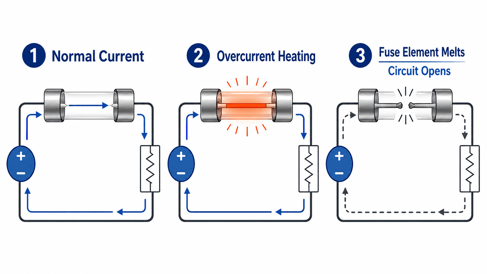
A fuse is both the sensing element and the interrupting element. It does not wait for a separate relay signal; the conductive element itself responds thermally to excessive current.
What is a Fuse?
A fuse is a sacrificial protective device installed in series with a circuit. Under normal conditions, current flows through the fusible element with limited heating. When current becomes excessive for long enough, the element melts, an arc forms inside the fuse, and the fuse body helps extinguish that arc so the circuit is isolated.
In power systems engineering, a fuse is not selected by amp rating alone. A safe application also depends on system voltage, available short-circuit current, load inrush, conductor ampacity, equipment damage limits, enclosure conditions, coordination with upstream devices, and whether the circuit is AC or DC.
A fuse protects against overcurrent. It does not replace grounding, insulation coordination, disconnecting means, arc-flash analysis, protective relays, or proper equipment short-circuit current ratings.
Fuse Ratings Explained: Current, Voltage, and Interrupting Rating
A fuse label may look simple, but each rating answers a different engineering question. The current rating tells you the normal current the fuse is intended to carry. The voltage and interrupting ratings tell you whether the fuse can safely clear a fault at the installation point. The speed, class, and curve shape tell you how the fuse behaves before it opens.
A 30 A fuse may carry a load near that range, but its interrupting rating may be thousands of amps depending on the fuse class and product. The interrupting rating is compared against available short-circuit current, not normal load current.
| Fuse rating or characteristic | What it means | Engineering implication |
|---|---|---|
| Current rating | The continuous current level associated with the fuse size and product family. | Must be coordinated with conductor ampacity, load current, equipment limits, and applicable derating rules. |
| Voltage rating | The maximum circuit voltage at which the fuse is designed to interrupt safely. | A fuse can melt but still fail dangerously if its voltage rating is too low for the system. |
| Interrupting rating | The maximum available fault current the fuse can safely interrupt at its rated voltage. | Must exceed the available short-circuit current at the fuse location. |
| AC or DC rating | Whether the fuse is suitable for alternating current, direct current, or both. | DC circuits can sustain arcs more severely, so AC and DC fuse applications should not be assumed interchangeable. |
| Time-current curve | The relationship between current magnitude and fuse opening time. | Used to evaluate nuisance operation, equipment protection, and selective coordination. |
| Current-limiting performance | The ability to reduce peak fault current and let-through energy during high-current faults. | Can reduce equipment stress, arc energy, and downstream damage when applied correctly. |
| Fuse class or type | A standardized or manufacturer-defined family with specific dimensions and performance limits. | Helps prevent unsafe substitutions and ensures compatibility with holders, disconnects, and equipment markings. |
AC Fuses vs DC Fuses
AC and DC fuse applications are not automatically interchangeable. AC current naturally crosses zero every half-cycle, which helps extinguish the arc after the fuse element melts. DC current does not naturally cross zero, so the fuse body, element geometry, filler material, and arc-quenching design must be suitable for the DC voltage and circuit energy.
| Application question | AC fuse concern | DC fuse concern |
|---|---|---|
| Arc interruption | Current zero crossings help the fuse clear the arc. | The fuse must force and extinguish the arc without natural zero crossings. |
| Voltage rating | Must meet or exceed the AC system voltage. | Must be specifically rated for the DC voltage and circuit configuration. |
| Typical examples | Panelboards, feeders, transformers, motors, and control circuits. | PV strings, battery systems, DC drives, rectifiers, and DC control circuits. |
Common Fuse Types and Fuse Classes
Different fuse types exist because the same overcurrent level can mean different things in different circuits. A motor starting event, transformer energization, semiconductor fault, PV string fault, and control-circuit short all place different demands on the fuse.
| Fuse type or class | Typical context | Why it matters |
|---|---|---|
| Fast-acting fuse | Control circuits, sensitive components, and loads with limited inrush. | Can open quickly during overloads but may nuisance-open if applied to loads with high starting current. |
| Time-delay fuse | Motors, transformers, and circuits with temporary inrush or magnetizing current. | Allows short-duration starting current while still clearing sustained overcurrent. |
| Class CC | Control circuits, compact equipment, and small branch circuits. | Often used where compact size, rejection features, and current limitation are valuable. |
| Class J | Industrial feeders, equipment panels, and fused switches. | Common in power distribution where high interrupting rating and current limitation are needed. |
| Class RK1 or RK5 | Industrial circuits using rejection-style fuseholders. | Different classes can have different current-limiting behavior even at the same amp rating. |
| Class L | Large services, large feeders, and high-current distribution equipment. | Used where high continuous current and high fault-interrupting capability are required. |
| Semiconductor fuse | Drives, rectifiers, inverters, and power electronics. | Selected for very low let-through energy to protect devices that can fail faster than general-purpose equipment. |
| PV or DC fuse | Solar strings, battery systems, and other direct-current circuits. | Must be specifically rated for the DC voltage and available fault-current conditions. |
Fuse class language should not be treated as decoration. It affects physical fit, rejection features, current limitation, holder compatibility, and replacement control.
Fast-Acting vs Time-Delay Fuses
Fuse speed is one of the most important practical selection decisions. A fast-acting fuse may protect sensitive equipment quickly, but it can nuisance-open on circuits with normal inrush. A time-delay fuse can tolerate temporary inrush while still opening for sustained overloads or faults.
| Condition | Fast-acting fuse | Time-delay fuse |
|---|---|---|
| Sensitive electronics | Often preferred where quick interruption is needed. | May allow more energy than the equipment can tolerate unless specifically selected. |
| Motor starting | May nuisance-open during normal starting current. | Often better suited because it can ride through short starting events. |
| Transformer energization | May open during magnetizing inrush. | Often used where brief inrush is expected but sustained faults must still clear. |
| Short-circuit protection | Can clear rapidly when properly rated. | Still clears short circuits, but its delay behavior must coordinate with equipment limits. |
Current-Limiting Fuses and Let-Through Energy
During a high-current short circuit, the prospective fault current may rise toward a large peak limited mainly by the source and circuit impedance. A current-limiting fuse interrupts fast enough that the actual current let through to the equipment is much lower than the current that would have flowed without the fuse.
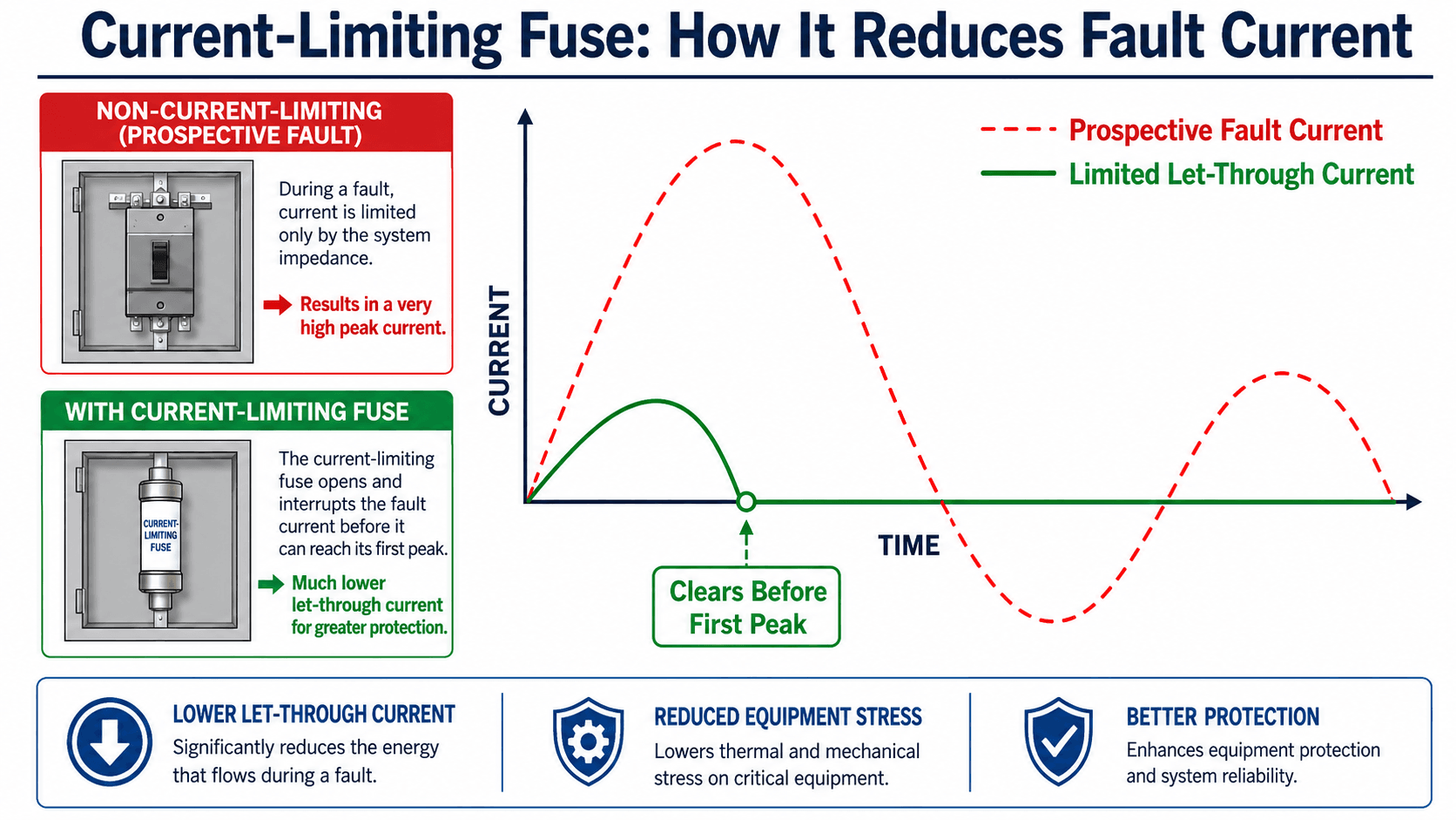
The thermal stress associated with fault current is often discussed using the I²t concept. Higher current and longer clearing time both increase heating, so a fuse that clears quickly can reduce damage even when the available fault current is very high.
I²t is a useful way to think about thermal energy, but actual fuse selection should use tested manufacturer let-through data, time-current curves, equipment ratings, and project-specific protection requirements.
How to Read a Fuse Time-Current Curve
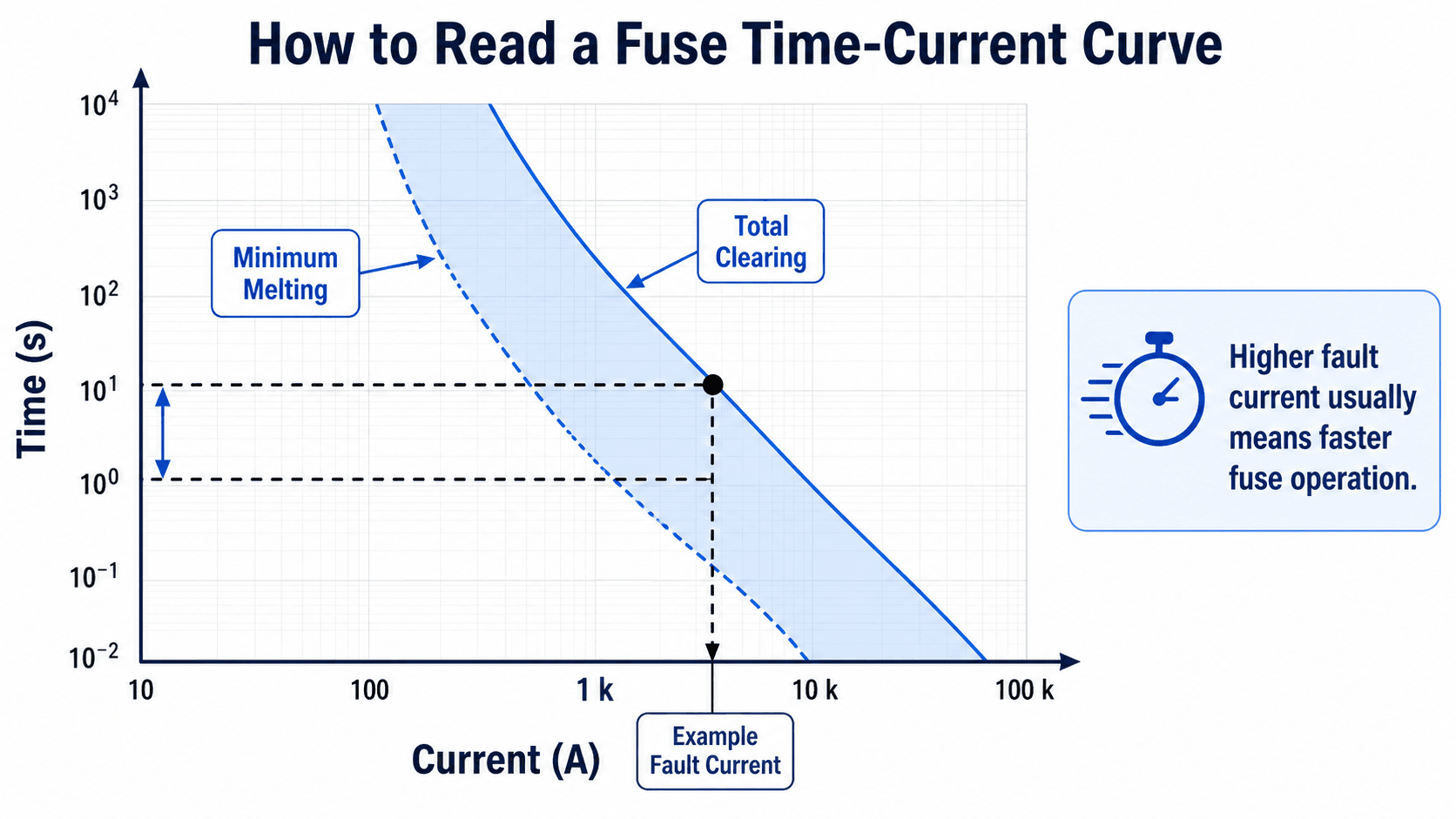
A fuse time-current curve shows how long a fuse takes to operate at different current levels. Current is usually plotted on the horizontal axis and time on the vertical axis, often on logarithmic scales. Available fault current is commonly discussed as RMS symmetrical current, while current-limiting performance may also involve peak let-through current.
Minimum melting versus total clearing
Minimum melting is the approximate point where the fuse element begins to melt. Total clearing includes the full interruption process, including arc extinction. For coordination studies, engineers care about both because a downstream fuse must clear before an upstream device unnecessarily opens.
Why curves are used for coordination
A downstream branch fuse, feeder fuse, upstream breaker, and transformer primary fuse may all see the same fault current differently. Time-current curves help engineers compare which device should operate first and whether upstream backup protection remains properly delayed.
How to Select a Fuse for a Power System
Fuse selection starts with the load, but it cannot stop there. A correct application verifies the normal current, the fault current, the system voltage, the interrupting requirement, and the way the fuse coordinates with surrounding protective devices.
Start with continuous load current, confirm conductor and equipment ratings, choose a fuse family suitable for the circuit type, verify voltage and interrupting ratings, check inrush behavior, review the time-current curve, then confirm coordination with upstream and downstream devices.
| Selection check | What to look for | Why it matters |
|---|---|---|
| Normal load current | Expected continuous current, duty cycle, and load growth margin. | The fuse must carry normal load without nuisance opening while still protecting the circuit. |
| System voltage and AC/DC type | Nominal voltage, maximum operating voltage, and whether the circuit is AC or DC. | The fuse must interrupt the arc safely under the actual circuit conditions. |
| Available short-circuit current | Calculated or documented fault current at the fuse location. | The fuse interrupting rating must exceed the available fault current. |
| Inrush and starting current | Transformer magnetizing current, motor starting current, capacitor energization, or power-supply inrush. | A fast fuse may nuisance-open if temporary current is mistaken for a damaging fault. |
| Selective coordination | Whether the downstream protective device clears first for expected faults. | Good coordination limits outages to the smallest practical part of the system. |
| Equipment SCCR | The short-circuit current rating of panels, assemblies, drives, and protected equipment. | The fuse may be part of the equipment’s tested or marked short-circuit protection scheme. |
| Replacement control | Fuse class, holder type, physical rejection features, and maintenance labeling. | Wrong replacements can defeat the original protection design even if they physically fit. |
Fuse Selection Example: 480 V Feeder Circuit
Consider a 480 V AC feeder supplying equipment with a 72 A continuous load. The available short-circuit current at the panel is 22 kA RMS symmetrical, and the load has moderate inrush during startup. A simple amp-rating-only replacement is not enough for this application.
Step 1: Start with normal load current
The fuse must carry the expected continuous load without nuisance operation. The engineer checks the load current, conductor ampacity, enclosure conditions, and whether continuous loading or ambient temperature requires derating.
Step 2: Verify voltage and interrupting rating
The fuse voltage rating must be suitable for the 480 V AC system, and the interrupting rating must exceed 22 kA at the installation point. A fuse with the correct amp rating but inadequate interrupting rating is not acceptable.
Step 3: Check inrush and coordination
Because the load has moderate inrush, a time-delay or appropriately selected current-limiting fuse may be needed. The engineer then reviews the time-current curve against upstream protection so the nearest protective device clears first for expected downstream faults.
In this example, the design decision depends on at least four checks: load current, voltage rating, interrupting rating above 22 kA, and time-current behavior that tolerates inrush while still coordinating with upstream protection.
Where Fuses Are Used in Power Systems
Fuses appear at many levels of a power system because they are compact, fast, and reliable when applied correctly. The engineering reason for using a fuse changes by location: sometimes the fuse protects a conductor, sometimes a transformer, sometimes a control circuit, and sometimes the fuse is chosen to reduce fault energy into sensitive equipment.
- Feeders and branch circuits: Fuses provide overcurrent protection for conductors and downstream equipment.
- Transformers: Primary-side fuses can isolate transformer faults and coordinate with secondary protection.
- Motor circuits: Time-delay fuses may ride through starting current while still clearing faults.
- Switchgear and panelboards: Fuses may be installed in fused switches, motor control centers, or distribution equipment.
- PV and battery systems: DC-rated fuses help isolate strings, conductors, and equipment where arc interruption is more demanding.
- Power electronics: Semiconductor fuses limit energy into devices that cannot tolerate high I²t.
A fuse that works well in one location may be wrong in another location with the same load current. The upstream source strength, enclosure, fault current, inrush, and maintenance replacement practice can change the correct choice.
Fuse vs Circuit Breaker: Practical Tradeoffs
Fuses and circuit breakers both protect circuits from overcurrent, but they do not behave the same way. The choice is not simply old technology versus new technology. It depends on interrupting needs, reset requirements, current limitation, coordination, maintenance, cost, and how the equipment is expected to be operated.
| Decision point | Fuse | Circuit breaker |
|---|---|---|
| After operation | Usually must be replaced. | Usually can be reset after the fault is investigated. |
| Current limitation | Current-limiting fuses can reduce peak fault current and energy. | Some breakers provide current limitation, but performance depends on breaker type and settings. |
| Adjustability | Usually fixed by fuse type and size. | Many trip units allow adjustable pickup, delay, and protection functions. |
| Maintenance risk | Wrong replacement fuse can compromise protection. | Resetting without finding the fault can re-energize a dangerous condition. |
| Coordination | Can coordinate well when fuse ratios and curves are selected correctly. | Can coordinate well with properly selected trip units and settings. |
| Switching function | A fuse alone is not a switch; it may be used inside a fused disconnect. | A breaker commonly provides both interruption and switching in one device. |
For broader protection context, see the Turn2Engineering guide to overcurrent protection and the related page on circuit breakers.
Why Does a Fuse Blow?
A blown fuse means the fuse experienced enough current and time to operate, but the cause is not always a simple overload. Before replacing a fuse, the circuit should be reviewed for the condition that caused the operation.
| Possible cause | What it looks like | Practical check |
|---|---|---|
| Actual overload | Load current is above the circuit’s intended operating range. | Measure load current and compare it with conductor and equipment ratings. |
| Short circuit or ground fault | Fuse opens suddenly, often during energization or after equipment failure. | Inspect downstream conductors, terminals, insulation, and equipment before replacement. |
| Normal inrush with wrong fuse speed | Fuse opens during motor starting, transformer energization, or capacitor switching. | Review the time-current curve and consider whether a time-delay fuse is appropriate. |
| Poor holder contact | Localized heating, discoloration, loose clips, or repeated fuse operation. | Inspect fuse clips, holder temperature, corrosion, and mechanical fit. |
| Wrong replacement fuse | Repeated nuisance openings or unsafe non-coordination after maintenance. | Verify fuse class, voltage rating, interrupting rating, speed, and physical rejection features. |
Engineering Judgment and Field Reality
Fuse behavior in a real installation depends on more than a neat schematic. Ambient temperature inside an enclosure, loose clips, aging holders, poor ventilation, harmonic heating, high fault current, nuisance inrush, and maintenance substitutions can all change whether the protection works as intended.
Fuse holders matter too. Loose clips, corrosion, heat damage, wrong physical size, missing rejection features, or undocumented spare-fuse practices can defeat the original protection design even when the original fuse selection was correct.
One of the most dangerous shortcuts is replacing a blown fuse with a larger fuse to “stop it from blowing.” That can shift damage from the fuse to conductors, terminals, equipment, or the next upstream device.
When This Breaks Down
The simplified idea that “a fuse blows when current is too high” is useful for beginners, but it breaks down when the fuse must be applied in an engineered power system. In real design work, timing, energy, voltage, and coordination details control whether the protection is acceptable.
- High inrush loads: A load can briefly draw several times its normal current without being faulted.
- Low-level faults: A fault current may be high enough to overheat equipment but not high enough to clear instantly.
- DC circuits: Arc interruption is more demanding because the current does not naturally cross zero each cycle.
- Series protective devices: Downstream and upstream fuses or breakers can overlap unless curves and ratios are checked.
- Backup or specialty fuses: Some fuse types have application limits and should not be assumed to clear every possible overload condition.
- Incorrect replacement: A physically similar fuse may have a different speed, interrupting rating, voltage rating, or class.
Common Fuse Mistakes and Practical Checks
Many fuse problems come from treating the fuse as a simple replaceable part instead of a protective device with a specific duty. The safest review checks both the electrical requirements and the maintenance reality of how the fuse will be replaced later.
- Matching only the amp rating: Voltage rating, interrupting rating, speed, and class can be just as important.
- Using an AC-only fuse in a DC circuit: A DC fault may not clear safely with an unsuitable fuse.
- Ignoring available fault current: A fuse must be able to interrupt the fault current available at its installed location.
- Ignoring nuisance operation: Transformer, motor, and capacitor inrush can open an incorrectly selected fast-acting fuse.
- Bypassing or upsizing fuses: This may leave conductors and equipment unprotected during the next fault.
A blown fuse is a symptom, not just a failed part. Before replacement, the circuit should be checked for overload, short circuit, ground fault, wrong fuse type, poor holder contact, or abnormal operating conditions.
Engineering References and Design Guidance
Fuse applications should be checked against project requirements, equipment markings, manufacturer data, and applicable electrical codes. The most useful technical references for understanding fuse behavior are time-current curves, let-through data, interrupting ratings, and coordination guidance.
- Eaton Bussmann technical reference: fuse time-current curve guidance explains how fuse curves use current and time axes and how curves are applied in selective coordination studies.
- Project-specific criteria: Equipment short-circuit current ratings, owner standards, replacement policies, and authority having jurisdiction requirements may control final selection.
- Engineering use: Designers use these references to verify fuse speed, coordination, current limitation, and interrupting ability rather than relying on the nameplate amp rating alone.
Frequently Asked Questions
A fuse is an overcurrent protection device that opens a circuit when excessive current heats and melts its internal element. It is used to protect conductors and equipment from overloads and short circuits, but it must be correctly rated for current, voltage, fault current, and application.
A fuse typically opens once and must be replaced, while a circuit breaker can usually be reset after it trips. Fuses can be very fast and current-limiting, but breakers provide switching, adjustable trip units in many applications, and easier restoration after a trip.
Fuse voltage rating matters because the fuse must safely interrupt the arc that forms when the element opens. A fuse with the wrong voltage rating may melt but fail to clear the fault safely, especially in DC circuits where there is no natural current zero crossing.
A current-limiting fuse is designed to interrupt high fault current before the current reaches its full prospective peak. This reduces let-through current, thermal energy, mechanical stress, and potential equipment damage during severe short-circuit events.
A fuse should not be replaced with a higher amp fuse unless the circuit, conductors, equipment, and protection requirements have been reviewed for that rating. Upsizing a fuse to stop nuisance blowing can leave conductors and equipment underprotected.
Summary and Next Steps
Fuses are simple in concept but highly engineered in application. They protect circuits by using current-generated heat to melt an internal element and interrupt the circuit before overloads or short circuits cause unacceptable damage.
The strongest fuse applications check more than amp rating. Engineers review voltage, interrupting capacity, AC/DC suitability, time-current behavior, current limitation, inrush, coordination, equipment SCCR, holder condition, and replacement control before treating a fuse as acceptable.
Where to go next
Continue your learning path with related Turn2Engineering resources.
-
Overcurrent Protection
Learn how fuses, breakers, relays, overloads, and coordination fit into the broader protection strategy.
-
Switchgear
See how protective devices are integrated into power distribution equipment and switching assemblies.
-
Protective Relays
Compare fuse operation with relay-based protection that measures system quantities and commands breakers to trip.