Key Takeaways
- Core idea: Fault analysis estimates how abnormal electrical faults behave so a power system can be protected and equipment can be rated correctly.
- Engineering use: Engineers use fault analysis to size breakers, check switchgear duty, coordinate relays, evaluate grounding effects, and isolate faults safely.
- What controls it: Source strength, transformer impedance, conductor impedance, grounding method, motor contribution, X/R ratio, and fault location strongly affect calculated fault current.
- Practical check: A fault study should review both maximum fault current for equipment duty and minimum fault current for protective device sensitivity.
Table of Contents
Introduction
Fault analysis is the process of studying abnormal electrical faults in a power system to estimate fault current, identify the fault type, check equipment duty, and coordinate protective devices. It connects circuit theory to real protection decisions, including relay settings, breaker interrupting ratings, grounding behavior, and how quickly a faulted section can be isolated.
Main Types of Power System Faults
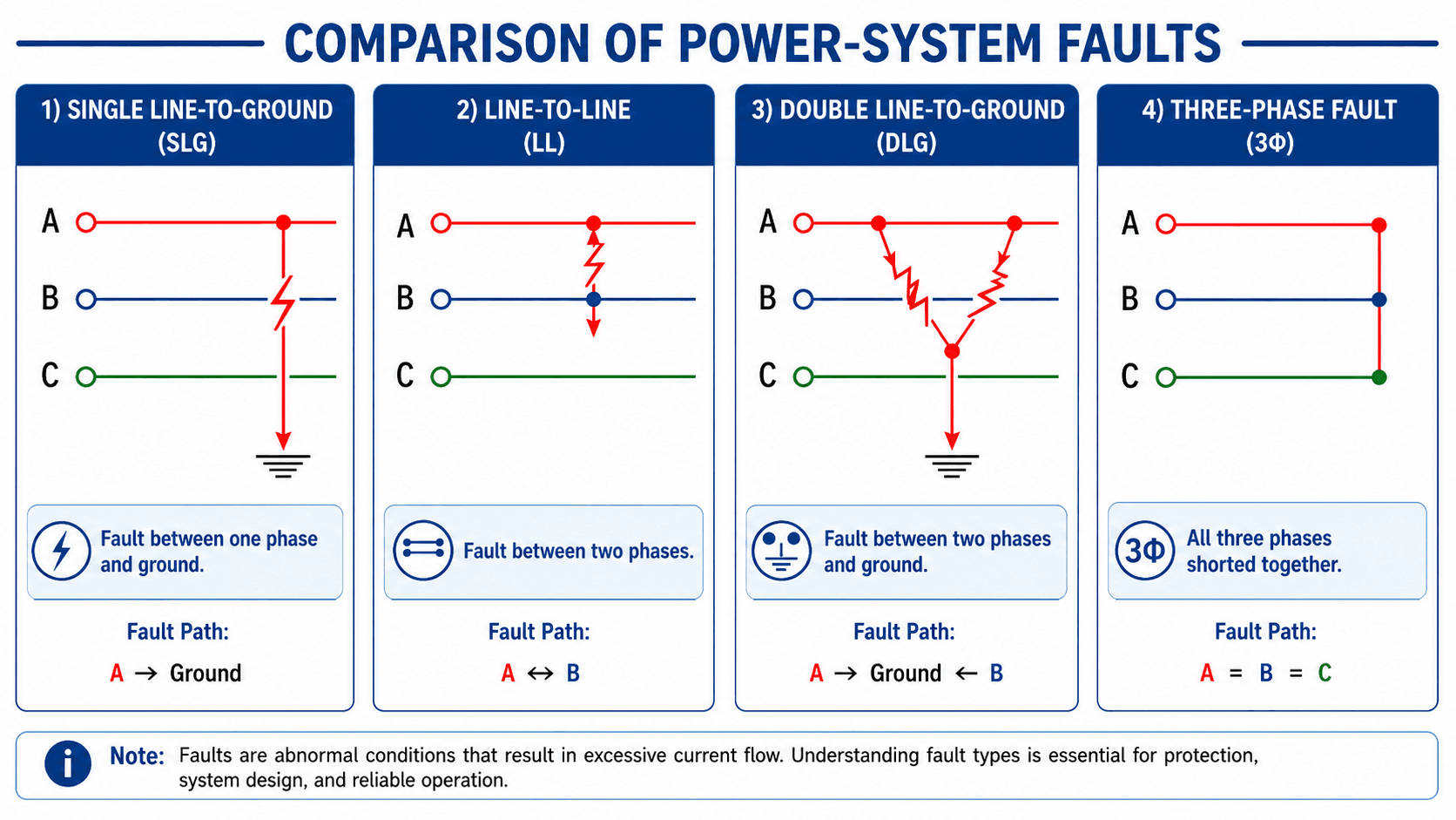
The fault path controls the analysis method. Ground faults depend heavily on the grounding system because zero-sequence current needs a physical return path. A balanced three-phase fault is often treated as all three phases shorted together; a three-phase-to-ground case can also be studied when the system model requires it.
What Is Fault Analysis?
Fault analysis is the engineering study of short circuits and other abnormal current paths in a power system. It asks a practical question: if a conductor, bus, cable, transformer, or piece of equipment fails in a specific way, how much current will flow and what protective device should operate?
In power systems engineering, fault analysis is not just a classroom exercise. It supports breaker interrupting ratings, relay pickup settings, fuse coordination, switchgear evaluation, grounding design, transformer protection, and downstream safety studies. A simple fault diagram may show one bright arc, but the actual result depends on source impedance, transformer impedance, conductor length, motor contribution, grounding, X/R ratio, and the exact location of the fault.
Fault analysis is closely related to short circuit analysis, but the term is often used more broadly. Short-circuit analysis usually emphasizes available fault current and equipment duty, while fault analysis also includes fault type, sequence networks, protection response, and model interpretation.
| Term | Main purpose | Typical output |
|---|---|---|
| Fault analysis | Understand fault type, current path, fault magnitude, and protection response. | Fault current, fault classification, sequence-network behavior, and affected equipment. |
| Short-circuit study | Calculate available short-circuit current and compare it with equipment duty. | Maximum and minimum short-circuit currents, equipment adequacy, and duty reports. |
| Protection coordination | Set protective devices so the correct relay, fuse, or breaker operates first. | Relay settings, time-current curve review, selectivity checks, and backup protection logic. |
| Arc flash study | Estimate thermal energy exposure during an arcing fault event. | Incident energy, working distance assumptions, labels, and PPE-related outputs. |
How Fault Analysis Works in a Power System
A fault changes the normal load-current path into a low-impedance or abnormal current path. Instead of current flowing through intended loads, current may flow phase-to-ground, phase-to-phase, or through all three phases at once. The system voltage, equivalent impedance, grounding method, rotating-machine contribution, and protective device clearing time determine how severe the fault becomes.
Symmetrical faults
A symmetrical fault affects all three phases equally. The classic example is a balanced three-phase fault. Because the system remains balanced, the analysis can often be simplified to one phase using the positive-sequence network. Three-phase faults are usually less common than ground faults, but they are important because they can produce severe current levels and are often checked for equipment interrupting duty.
Unsymmetrical faults
Unsymmetrical faults affect the phases unequally. Single line-to-ground, line-to-line, and double line-to-ground faults all create unbalance. These faults usually require symmetrical components because the original three-phase system is harder to solve directly once the phase currents and voltages are no longer balanced.
Ground faults and the return path
Ground faults are strongly controlled by the grounding system. A solidly grounded system can allow high ground-fault current, while resistance-grounded or impedance-grounded systems intentionally limit current. Ungrounded and high-impedance systems can behave very differently from the simple diagrams, especially during intermittent or arcing faults. This is why grounding techniques are a major part of interpreting fault analysis results.
Fault Current Calculation and Key Inputs
At a basic level, fault current is controlled by the driving voltage and the equivalent impedance between the source and the fault. A simplified three-phase bolted fault calculation can be written as:
This equation is useful for understanding the relationship, but real studies often use per-unit methods or software models because transformers, cables, generators, motors, grounding equipment, and protective devices all contribute to the final result.
- \(I_{3\phi}\) Three-phase fault current, commonly reported in amperes or kiloamperes.
- \(V_{LL}\) Line-to-line system voltage at the faulted bus before the fault.
- \(Z_{eq}\) Equivalent impedance from the source to the fault, including source, transformer, conductor, and equipment impedance where applicable.
The same idea can be expressed more generally as \(I_f = V_{th}/Z_{th}\), where \(V_{th}\) and \(Z_{th}\) are the Thevenin equivalent voltage and impedance seen from the fault location. That viewpoint is useful because fault current is not a fixed property of a panel, transformer, or feeder. It changes with the system behind the fault.
Maximum and minimum fault current cases
A complete study does not only look for the largest number. Maximum available fault current is used to check breaker interrupting duty, switchgear withstand, bus bracing, and short-time equipment ratings. Minimum available fault current is used to confirm that relays, fuses, and breakers can still detect and clear remote or impedance-limited faults.
Symmetrical RMS current and asymmetrical current
Basic calculations often report symmetrical RMS fault current, but actual fault current can include a decaying DC offset. The X/R ratio affects how large and persistent this asymmetrical component is. That matters because breakers and switchgear may need to be evaluated for interrupting duty, momentary duty, close-and-latch duty, and short-time withstand, not only steady symmetrical current.
| Fault analysis input | Why it matters | Engineering implication |
|---|---|---|
| Utility or upstream source strength | Defines how much current the upstream system can deliver into the fault. | Outdated utility fault data can understate or overstate breaker and switchgear duty. |
| Transformer impedance | Transformer percent impedance often dominates low-voltage available fault current. | A small change in transformer impedance can significantly change calculated downstream fault current. |
| Conductor and cable impedance | Feeder length and conductor size reduce fault current farther from the source. | Remote faults may be harder for protective devices to detect quickly. |
| Grounding method | Ground-fault current depends on the available return path through neutral, ground, or grounding impedance. | Single line-to-ground fault results can be wrong if grounding is modeled incorrectly. |
| Motor and generator contribution | Rotating machines can feed current into a fault for a short time after the fault begins. | Ignoring machine contribution can affect equipment duty and protective device coordination. |
| X/R ratio | Controls the asymmetrical offset and how quickly the DC component decays. | Can affect momentary, close-and-latch, and interrupting-duty evaluations. |
What Fault Analysis Results Are Used For
Fault analysis results are most useful when they lead to a specific engineering decision. The same study may produce several outputs, and each output supports a different protection, rating, or reliability check.
| Result from fault analysis | Common engineering use | What it helps verify |
|---|---|---|
| Maximum three-phase fault current | Breaker interrupting rating and switchgear duty checks. | Equipment can interrupt or withstand the worst credible bolted fault at that location. |
| Minimum fault current | Relay sensitivity, fuse clearing, and remote feeder protection checks. | The intended device still detects and clears faults when current is low. |
| Ground-fault current | Ground-fault protection, grounding review, and zero-sequence evaluation. | The ground return path and protective device sensitivity are modeled correctly. |
| Fault current at remote feeder end | Long-feeder protection review. | Voltage drop, conductor impedance, and distance have not made the fault too small to detect. |
| X/R ratio and asymmetrical current | Momentary duty and interrupting-duty evaluation. | Equipment ratings are checked against realistic peak and offset current behavior. |
| Time-current coordination results | Relay, fuse, and breaker selectivity review. | The nearest appropriate device operates before unnecessary upstream tripping occurs. |
Symmetrical Components in Fault Analysis
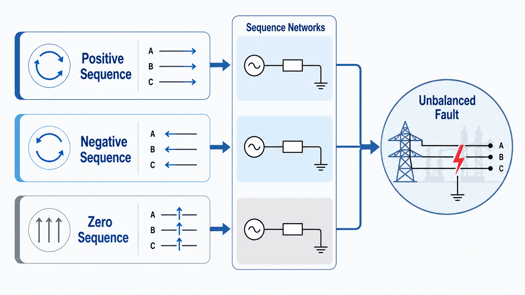
Symmetrical components are used when a fault creates an unbalanced three-phase condition. Instead of trying to solve the unbalanced phase quantities directly, the system is separated into positive, negative, and zero sequence networks. These sequence networks are then connected differently depending on the fault type.
Positive, negative, and zero sequence
The positive-sequence network represents the normal balanced phase rotation of the system. The negative-sequence network represents reverse phase rotation caused by unbalance. The zero-sequence network represents in-phase currents on all three phases and is especially important for ground faults because it depends on the neutral, ground, transformer winding connections, and grounding equipment.
How sequence networks change by fault type
The sequence-network connection is one of the main differences between fault types. The table below gives a practical way to understand the relationship without turning the page into a full textbook derivation.
| Fault type | Sequence-network behavior | Practical meaning |
|---|---|---|
| Three-phase fault | Primarily positive-sequence network. | The system remains balanced, so the calculation is usually simpler than unbalanced fault cases. |
| Single line-to-ground fault | Positive, negative, and zero sequence networks are commonly connected in series. | The zero-sequence path and grounding method strongly affect the calculated current. |
| Line-to-line fault | Positive and negative sequence networks are involved; zero sequence is usually not involved. | The fault is unbalanced but does not need a ground return path. |
| Double line-to-ground fault | Positive, negative, and zero sequence networks are involved in a more complex connection. | The result depends on both phase-to-phase behavior and the ground return path. |
How Fault Analysis Supports Protection Decisions
Fault analysis becomes useful when the calculated results are tied to protection decisions. A study should not stop at a current value in kiloamperes. The result must be compared against equipment ratings and used to determine whether protective devices can detect, interrupt, and isolate the fault selectively.
- Circuit breaker duty: The breaker must be able to interrupt the calculated fault current at its application voltage.
- Switchgear and bus bracing: Equipment must withstand the thermal and mechanical stress of the fault current until it is cleared.
- Relay settings: Protective relays need pickup and time-delay settings that detect faults without tripping unnecessarily for normal load or inrush conditions.
- Selective coordination: The nearest appropriate device should operate first so upstream sections remain energized when possible.
- Ground-fault sensitivity: Ground faults must be detected without assuming every fault behaves like a high-current bolted fault.
Related protection topics include protective relays, overcurrent protection, and transmission line protection.
A high available fault current is not automatically “worse” in every protection sense. High current may be easier to detect but harder to interrupt. Low-current ground faults may be easier on equipment duty but harder for protective devices to detect reliably.
Practical Fault Analysis Workflow
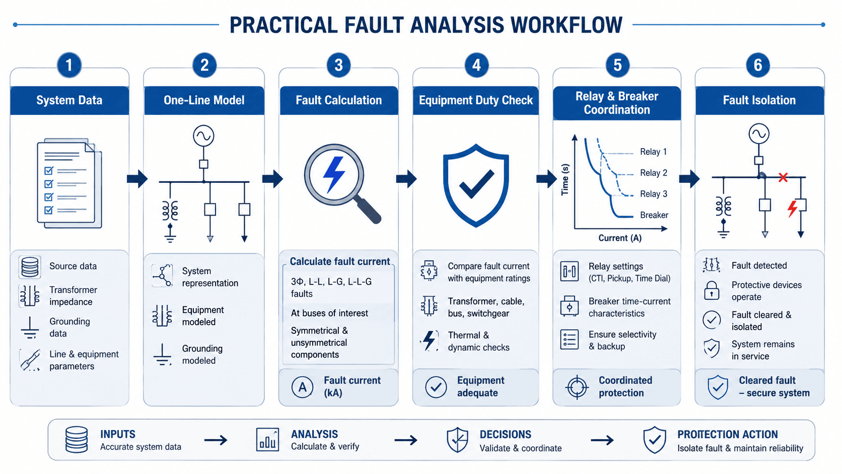
A practical fault analysis follows a repeatable workflow: gather accurate system data, build a one-line model, calculate fault currents at critical buses, compare the results with equipment ratings, coordinate protective devices, and confirm that the faulted section can be isolated without unnecessary outages.
Start with the one-line diagram
The one-line diagram is the backbone of the study. It should show sources, transformers, buses, breakers, fuses, cables, motors, generators, grounding equipment, and normally open or closed ties. If the one-line is wrong, the calculated fault current will be wrong even if the software or math is correct.
Calculate at the buses that matter
Engineers usually evaluate multiple fault locations, including service equipment, switchgear, motor control centers, panelboards, transformer secondary terminals, and remote feeder ends. The highest current location may control interrupting duty, while a remote low-current location may control relay sensitivity.
Convert results into protection action
The output should lead to a decision: equipment is acceptable, equipment needs replacement, relay settings need adjustment, grounding assumptions need review, or the system model requires correction. Fault analysis is most valuable when it leads to clear engineering action.
Fault Analysis Model Review Checklist
Before trusting a fault analysis result, review the model like a senior engineer would. The checklist below focuses on the inputs and assumptions that most often change the answer in a meaningful way.
Verify the one-line diagram first, then confirm source data, transformer impedance, grounding method, conductor data, machine contribution, protective device ratings, X/R ratio, and operating configuration. Only after the model is credible should the calculated current be used for breaker duty or relay coordination.
| Fault analysis check | What to look for | Why it matters |
|---|---|---|
| Utility source data | Confirm available fault current, X/R ratio, and whether the data is maximum, minimum, or present-day. | Maximum fault current affects interrupting duty; minimum fault current can affect relay sensitivity. |
| Transformer impedance | Use actual nameplate or project data instead of generic percent impedance values. | Transformer impedance is often the largest limiter of downstream fault current. |
| Grounding model | Check neutral grounding, transformer winding connection, grounding resistor values, and return paths. | Ground fault results can be drastically wrong if the zero-sequence path is modeled incorrectly. |
| Motor and generator contribution | Identify large motors, on-site generators, inverters, and operating configurations. | Local sources can contribute current into a fault and change equipment-duty results. |
| Protective device data | Confirm breaker ratings, fuse classes, relay curves, CT ratios, pickup settings, and time delays. | Fault current values are only useful if they are compared against the correct protective equipment data. |
| System configuration | Review normal and alternate switching states, tie breakers, emergency feeds, and temporary operating modes. | A different operating configuration can change both the magnitude and direction of fault current. |
Simple Fault Current Example
Consider a simplified three-phase fault on the secondary side of a transformer. If a 480 V system has an equivalent impedance of \(0.02\ \Omega\) from the source to the fault, the approximate three-phase bolted fault current is:
The result is approximately:
Example assumptions
This simplified example assumes a balanced three-phase bolted fault, fixed pre-fault voltage, and one equivalent impedance value. It does not separately model transformer X/R ratio, motor contribution, conductor heating, utility variation, or protective device time response.
Equipment-duty interpretation
If the available fault current is about 13.9 kA, a downstream breaker with a 10 kA interrupting rating would generally be inadequate for that location. A 22 kA breaker may be acceptable for interrupting duty, but the full review should still consider voltage rating, X/R ratio, equipment short-time ratings, series ratings if used, and the actual protective device coordination study.
Engineering Judgment and Field Reality
Real fault analysis is shaped by imperfect field data. Drawings may not match installed equipment, transformer nameplates may be hard to access, switch positions may change seasonally, and utility source data may be updated after system upgrades. Experienced engineers treat the study as a model that must be checked against the physical system, not as an unquestionable output.
The highest bolted fault current is not the only important case. A remote, arcing, or impedance-limited fault may produce lower current but still be dangerous because it may not trip the intended protective device quickly.
Field judgment is especially important when evaluating ground faults, long feeders, backup generation, temporary switching, and inverter-based sources. These cases can make fault current lower, shorter in duration, or directionally different from what a basic textbook example suggests.
When This Breaks Down
Simplified fault analysis breaks down when the assumptions no longer match the physical behavior of the system. A bolted fault model is useful for equipment-duty checks, but not every real fault is a zero-impedance metallic short.
- Arcing faults: Arc impedance can reduce current and change clearing behavior compared with a bolted fault.
- High-impedance ground faults: Fault current may be too low for standard overcurrent devices to detect quickly.
- Changing source conditions: Utility system upgrades, generator operation, or tie switching can change available fault current.
- Inverter-based resources: Inverters may limit fault current differently from synchronous machines and may not behave like traditional sources.
- Incorrect grounding assumptions: Ground-fault results can be misleading if neutral grounding, transformer winding connections, or return paths are wrong.
Common Mistakes and Practical Checks
The most common fault analysis mistakes are usually modeling mistakes, not math mistakes. The equations can be applied correctly and still produce a misleading answer if the system data is wrong.
- Using old utility data: Available fault current can change when the upstream utility network is modified.
- Ignoring transformer impedance tolerance: Actual impedance affects downstream current and may differ from assumptions used early in design.
- Only checking maximum current: Minimum fault current matters for whether protective devices operate reliably.
- Confusing load current with fault current: Load current is normal operating current; fault current is abnormal current limited mainly by system impedance.
- Skipping coordination review: A device may be rated to interrupt a fault but still trip out of sequence with upstream or downstream protection.
Do not treat one fault current value as valid for the entire system. Fault current changes by bus location, fault type, grounding path, operating configuration, source condition, and minimum-versus-maximum study case.
Engineering References and Design Guidance
Fault analysis affects equipment application and protection settings, so authoritative short-circuit study guidance is useful when moving from learning concepts to project work.
- IEEE 3002.3-2018: IEEE recommended practice for conducting short-circuit studies and analysis provides professional context for short-circuit studies, including fault-current calculation, device-duty evaluation, and the importance of modeling assumptions in industrial and commercial power systems.
- Project-specific criteria: Owner standards, utility data, equipment ratings, and the authority having jurisdiction may control how study results are applied on a specific project.
- Engineering use: The reference context helps engineers understand why calculated fault current must be tied to equipment duty, protective device coordination, and model validation rather than treated as an isolated number.
Frequently Asked Questions
Fault analysis is the study of abnormal electrical faults in a power system so engineers can estimate fault current, classify the fault type, check equipment duty, and coordinate protective devices such as relays, fuses, and circuit breakers.
The main power system fault types are single line-to-ground, line-to-line, double line-to-ground, and three-phase faults. Single line-to-ground faults involve one phase and ground, while three-phase faults involve all three phases and are typically treated as symmetrical faults.
They overlap, but they are not always used exactly the same way. Short-circuit analysis usually focuses on calculating available short-circuit current and equipment duty, while fault analysis can also include fault classification, sequence components, protection response, and practical troubleshooting.
Symmetrical components are used because many faults are unbalanced. By separating an unbalanced fault into positive, negative, and zero sequence networks, engineers can calculate fault behavior that is difficult to analyze directly in the original three-phase system.
A fault analysis typically needs a current one-line diagram, utility or source fault data, transformer impedance, conductor and cable data, grounding method, motor or generator contribution, operating configuration, and protective device ratings or settings.
Summary and Next Steps
Fault analysis explains how a power system behaves when an abnormal current path occurs. It identifies the fault type, estimates fault current, and connects the electrical model to real protection decisions.
The most important practical steps are to classify the fault, verify the one-line model, calculate fault current at critical buses, check equipment duty, and coordinate protective devices. Strong studies review maximum and minimum fault current, sequence-network behavior, grounding assumptions, source data, transformer impedance, conductor impedance, X/R ratio, and field configuration.
Where to go next
Continue your learning path with related Turn2Engineering resources.
-
Short Circuit Analysis
Learn how available short-circuit current is calculated and used for equipment-duty evaluation.
-
Protective Relays
Understand how relays detect faults and initiate breaker operation.
-
Overcurrent Protection
See how fuses, breakers, and relays protect equipment from excessive current.