Key Takeaways
- Core idea: A failure mechanism is the process that causes material damage, not just the visible broken part.
- Engineering use: Engineers use failure mechanisms to diagnose damage, improve material selection, adjust geometry, and prevent repeat failures.
- What controls it: Loading, stress concentration, temperature, environment, surface condition, material properties, time, and inspection history all matter.
- Practical check: The final fracture is often the last event, not the root cause; always look for where damage started.
Table of Contents
Introduction
Failure mechanisms are the physical, chemical, thermal, or mechanical processes that cause materials to lose function. They explain how damage begins and grows through fatigue, fracture, creep, corrosion, wear, overload, distortion, or buckling so engineers can identify causes, improve designs, and prevent repeat failures.
How Failure Mechanisms Progress from Initiation to Final Failure
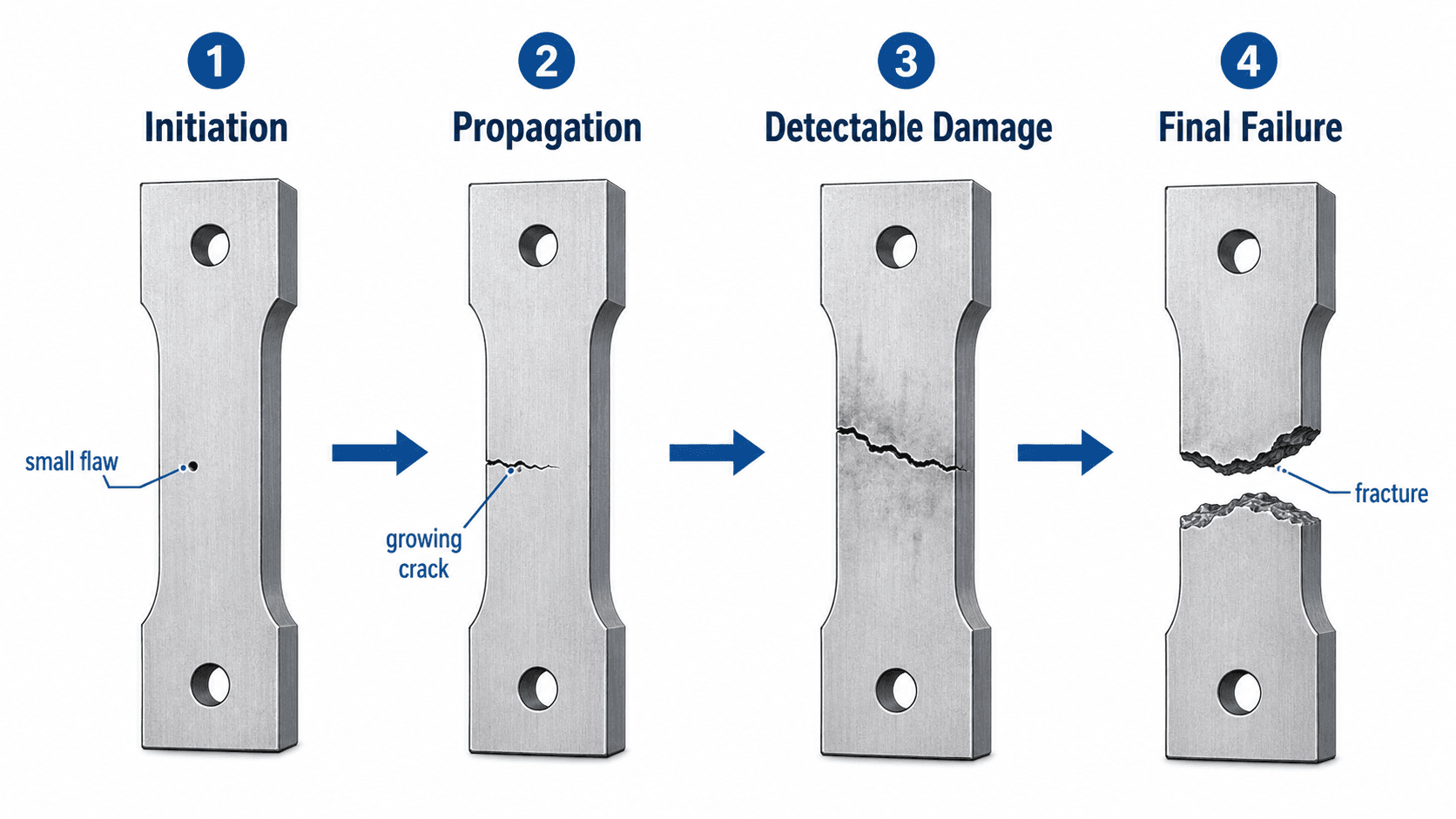
Start by looking for the initiation point. A small pit, notch, weld toe, thread root, scratch, inclusion, or sharp corner can control the entire failure sequence.
What Are Failure Mechanisms?
A failure mechanism is the underlying process that causes a material, component, or structure to stop performing as intended. It is not only the fact that something broke, bent, leaked, seized, or collapsed. It is the explanation for how that damage developed under real loading, environmental, thermal, manufacturing, and service conditions.
The main types of failure mechanisms in materials are fatigue, fracture, creep, corrosion, wear, overload, distortion, buckling, and combined mechanisms such as corrosion fatigue or stress corrosion cracking. Each mechanism has a different driver, warning sign, material property connection, and prevention strategy.
In materials science, failure mechanisms connect directly to material properties. Strength, ductility, toughness, hardness, fatigue resistance, corrosion resistance, and creep resistance all describe how a material responds to different failure risks. A material may perform well in a simple tensile test but still fail in service if the controlling mechanism is fatigue, corrosion, wear, creep, or stress corrosion cracking.
| Term | What it means | Example | Engineering use |
|---|---|---|---|
| Failure mode | The observable way the part stops working. | A shaft fractures near a keyway. | Describes the visible result. |
| Failure mechanism | The process that produced the damage. | Fatigue crack initiation and growth. | Explains how the damage developed. |
| Root cause | The underlying reason the mechanism was allowed to occur. | Sharp keyway radius, cyclic torque, poor surface finish, or misalignment. | Guides the corrective action. |
What condition allowed the damage to start, what mechanism allowed it to grow, and what final event caused the component to lose function?
This distinction matters because replacing a failed part with the same material may not solve the problem. If the mechanism was fatigue from a stress concentration, the replacement may still crack unless the geometry, surface finish, alignment, vibration, or load history is corrected.
Failure Mechanism Map
Failure mechanisms are easier to understand when grouped by the main driver. Some are controlled mostly by stress, some by environment, some by temperature and time, and some by surface contact. Real failures often sit between these categories.
| Failure mechanism family | Typical mechanisms | Primary driver | Engineering review focus |
|---|---|---|---|
| Mechanical | Overload, fracture, fatigue, plastic deformation, buckling | Stress, load path, geometry, restraint, cyclic loading | Stress concentration, section capacity, stiffness, flaw size, load history, and support conditions. |
| Environmental | Corrosion, oxidation, stress corrosion cracking, environmental stress cracking | Moisture, chemicals, salt, oxygen, temperature, material compatibility | Exposure, coatings, drainage, galvanic contact, crevices, pits, and chemical compatibility. |
| Time-dependent | Creep, stress relaxation, fatigue crack growth, thermal aging | Service time, temperature, sustained stress, repeated cycles | Operating temperature, duty cycle, time under load, material degradation, and inspection interval. |
| Surface and contact | Wear, fretting, erosion, rolling contact fatigue, galling | Sliding, rolling, abrasion, contact pressure, lubrication | Surface finish, hardness, lubrication, alignment, debris, clearance, and contact stress. |
| Combined | Corrosion fatigue, creep-fatigue, fretting fatigue, wear-assisted cracking | Multiple damage drivers acting together | Damage sequence, interaction between conditions, and which mechanism initiated the failure. |
A failure mechanism sequence is the order in which damage develops: the initiating condition, the mechanism that starts damage, the mechanism that accelerates it, and the final failure mode. This sequence is often more useful than a single label because it shows what must change to prevent recurrence.
A condition such as salt exposure, misalignment, high temperature, or poor surface finish is not usually the failure mechanism by itself. It is the condition that triggers a mechanism such as corrosion, wear, creep, or fatigue crack growth.
Common Types of Failure Mechanisms in Materials
Most material failures fall into a few major mechanism groups. Separating them helps engineers decide what to inspect, which property matters, and what design or maintenance action is most likely to prevent recurrence.
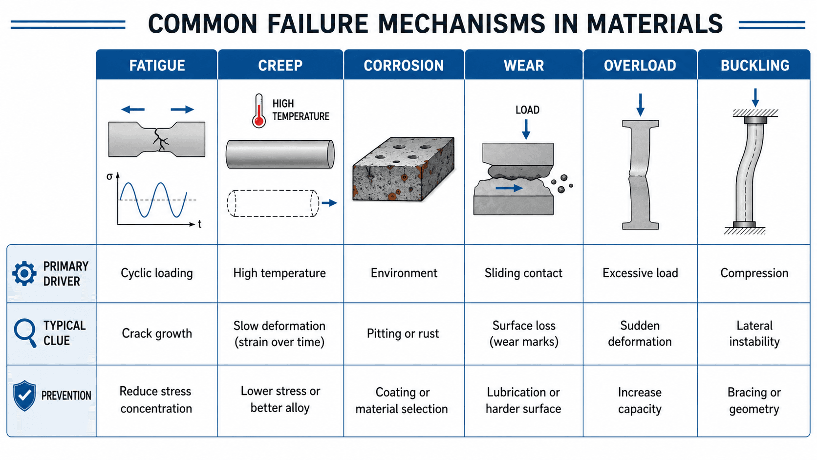
- Fatigue: progressive cracking from repeated or fluctuating load.
- Creep: long-term deformation from sustained stress, usually at elevated temperature.
- Corrosion: environmental material loss, pitting, or environmentally assisted cracking.
- Wear: surface damage caused by contact, sliding, abrasion, erosion, or fretting.
- Buckling: instability caused by compression and geometry rather than simple material rupture.
Fracture
Fracture occurs when a crack grows until the remaining material can no longer carry the load. Ductile fracture usually includes visible plastic deformation before separation, while brittle fracture can occur with little warning. Fracture toughness, toughness, ductility, flaw size, temperature, and stress concentration are key factors.
Fatigue
The fatigue failure mechanism is progressive crack growth caused by repeated or fluctuating stress. It is especially important in shafts, gears, welded joints, aircraft parts, springs, bridges, fasteners, and rotating machinery. A fatigue failure can occur even when the peak stress is below static tensile strength because repeated loading gradually grows a crack from a small flaw.
Creep
The creep failure mechanism is slow, permanent deformation under sustained stress, usually at elevated temperature. It matters in turbine blades, boiler tubes, exhaust systems, pressure equipment, polymers, solder joints, and high-temperature piping. The controlling factors are stress level, temperature, service time, and creep resistance.
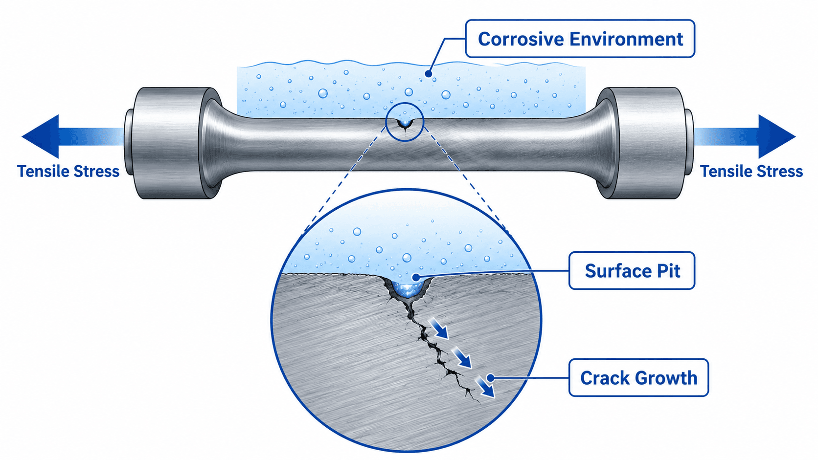
Corrosion
Corrosion is chemical or electrochemical degradation caused by the service environment. It can remove section thickness, create pits, weaken connections, roughen surfaces, or start cracks. Pitting corrosion is especially dangerous because a small pit can become a stress concentration and crack initiation site.
Wear
The wear failure mechanism is material loss from surfaces in contact. Common forms include abrasive wear, adhesive wear, erosive wear, fretting, and rolling contact wear. Hardness, lubrication, surface finish, contact pressure, debris, alignment, and material pairing often control whether wear remains acceptable or becomes a failure mechanism.
Overload
Overload occurs when the applied load exceeds the component’s capacity. It may cause yielding, tearing, crushing, shear failure, or sudden fracture. Unlike fatigue, overload often points to a single event or condition where the part was asked to carry more load than it was designed for.
Distortion
Distortion is a loss of shape, tolerance, alignment, or clearance. It can come from overload, residual stress, welding heat, thermal gradients, creep, machining, or uneven cooling. Distortion may not look as dramatic as fracture, but it can still make a part fail by causing binding, leakage, vibration, or loss of fit.
Buckling
Buckling is an instability failure, usually in slender members under compression. The material may not crush or fracture first; instead, the geometry becomes unstable and deflects sideways. Stiffness, slenderness, end restraints, imperfections, and bracing are often more important than tensile strength.
Material Properties That Control Failure
The best material is not always the strongest material. It is the material whose properties match the actual load, temperature, environment, geometry, manufacturing method, inspection plan, and service life. For a deeper foundation, review mechanical properties of materials.
| Failure risk | Important material properties | Why they matter |
|---|---|---|
| Yielding or overload | Yield strength, tensile strength, ductility | Controls whether a part permanently deforms, tears, or fractures under a high load. |
| Fatigue cracking | Fatigue strength, fracture toughness, surface hardness, ductility | Controls crack initiation, crack growth, and tolerance to small flaws. |
| Brittle fracture | Fracture toughness, ductility, impact toughness | Controls resistance to rapid crack growth, especially at low temperature or high constraint. |
| Creep deformation | Creep strength, temperature resistance, microstructural stability | Controls long-term deformation and rupture under sustained stress at elevated temperature. |
| Corrosion damage | Corrosion resistance, coating compatibility, chemical stability | Controls material loss, pitting, surface attack, and environmentally assisted cracking. |
| Wear damage | Hardness, toughness, wear resistance, surface finish | Controls scoring, fretting, debris generation, surface loss, and contact durability. |
| Distortion and buckling | Elastic modulus, yield strength, stiffness, thermal expansion | Controls shape change, instability, tolerance loss, and loss of alignment. |
This property connection is why failure analysis is not only about naming the broken condition. Engineers need to know whether the controlling property was strength, toughness, ductility, hardness, corrosion resistance, creep resistance, stiffness, or a combination of properties.
Combined Failure Mechanisms
Real-world failures often involve more than one mechanism. A part may corrode first, then fatigue from a pit. A hot component may creep while also cycling thermally. A bearing surface may wear, become misaligned, heat up, and then crack.
| Combined mechanism | How it works | Why it is dangerous |
|---|---|---|
| Corrosion fatigue | Cyclic loading grows cracks faster in a corrosive environment. | Fatigue life can drop sharply even when nominal stress appears acceptable. |
| Stress corrosion cracking | Tensile stress and a specific environment drive crack initiation and growth. | The surface may show limited general corrosion while cracks grow locally. |
| Creep-fatigue | High temperature, sustained stress, and cyclic loading act together. | Common in thermal equipment where start-stop cycles combine with hot operation. |
| Fretting fatigue | Small sliding motion damages a contact surface and creates fatigue initiation sites. | Can occur at bolted joints, splines, press fits, and contact interfaces. |
| Wear-assisted overheating | Progressive wear increases friction, heat, clearance, or vibration. | The final failure may look thermal or mechanical even though surface damage started the sequence. |
How Failure Mechanisms Change by Material Type
Metals, polymers, composites, ceramics, and coatings do not fail in exactly the same way. The service condition may be similar, but the material family changes the likely mechanism, the visible evidence, and the best prevention strategy.
| Material type | Common failure mechanisms | Engineering note |
|---|---|---|
| Metals | Fatigue, ductile fracture, brittle fracture, corrosion, creep, wear, buckling | Small cracks, pits, weld details, residual stress, and surface finish often control service life. |
| Polymers | Creep, stress relaxation, environmental stress cracking, UV degradation, thermal aging | Time, temperature, chemicals, and sustained stress can be more important than short-term strength. |
| Composites | Delamination, fiber breakage, matrix cracking, impact damage, moisture degradation | Damage may be hidden below the surface, and direction-dependent properties matter. |
| Ceramics | Brittle fracture, thermal shock, surface flaw growth, impact damage | Small surface flaws can dominate strength because ceramics have limited ductility. |
| Coatings | Adhesion loss, blistering, cracking, abrasion, corrosion underfilm | Coating failure can expose the substrate and trigger corrosion or wear underneath. |
How Engineers Identify Failure Mechanisms
A good failure analysis does not jump straight to the most visible crack or broken surface. It works backward from evidence, service history, material condition, loading, environment, and manufacturing details.
Document the failure condition → preserve damage surfaces → identify the visible failure mode → locate the initiation site → connect evidence to a likely mechanism → separate the mechanism from the root cause.
How Engineers Look for the Initiation Point
Engineers usually inspect geometric discontinuities, surface pits, weld toes, thread roots, holes, inclusions, coating defects, fretting marks, and heat-affected zones first because many progressive failures begin where stress, environment, or contact damage is concentrated.
| Evidence clue | Possible mechanism | What to check next |
|---|---|---|
| Beach marks, ratchet marks, or crack growth bands | Fatigue | Cyclic loading, vibration, stress concentrations, surface finish, and initiation site. |
| Pits at or near a crack origin | Corrosion fatigue or stress corrosion cracking | Environment, tensile stress, material susceptibility, coating damage, and drainage. |
| Necking or visible plastic deformation | Ductile overload | Load event, section capacity, material strength, temperature, and restraint conditions. |
| Flat fracture surface with little deformation | Brittle fracture | Fracture toughness, low temperature, flaw size, impact loading, and constraint. |
| Bulging, sagging, oxide scale, or long-term deformation | Creep or high-temperature degradation | Service temperature, stress level, operating time, material grade, and thermal history. |
| Polished grooves, debris, scoring, or fretting marks | Wear, fretting, or contact fatigue | Lubrication, alignment, contact pressure, hardness, debris control, and clearance. |
Visible Symptoms and Likely Mechanisms
| Visible symptom | Likely mechanisms to consider | First engineering check |
|---|---|---|
| Crack near a hole, thread, weld, or shoulder | Fatigue, brittle fracture, stress corrosion cracking | Find the crack origin and check stress concentration, surface condition, and cyclic loading. |
| Rust, pitting, thinning, deposits, or leak path | Corrosion, pitting corrosion, corrosion fatigue | Review environment, material compatibility, drainage, coatings, and galvanic contact. |
| Slow sagging, bulging, or permanent deformation | Creep, thermal distortion, plastic deformation | Check temperature, time under load, stress level, and material creep resistance. |
| Scoring, debris, heat, noise, or looseness | Wear, fretting, lubrication failure, contact fatigue | Check contact pressure, lubrication, alignment, hardness, and contamination. |
| Sudden sideways deflection or local wrinkling | Buckling or instability | Check compression load, slenderness, bracing, eccentricity, and end restraints. |
Failure Mechanism Examples in Engineering
Examples make the difference between naming a mechanism and understanding how it appears in real equipment. The same visible failure can come from different mechanisms, so surrounding evidence matters.
| Component or system | Visible failure | Likely mechanism | Why it happens |
|---|---|---|---|
| Rotating shaft | Crack near a keyway, shoulder, or thread | Fatigue | Cyclic torque combines with a stress concentration and surface flaw. |
| Steel bridge member | Section loss, cracking, or connection deterioration | Corrosion fatigue | Deicing salts and moisture combine with repeated traffic loading. |
| Boiler tube or high-temperature pipe | Bulging, thinning, or rupture | Creep | Internal pressure acts for long periods at elevated temperature. |
| Bearing race | Pitting, spalling, heat, or vibration | Rolling contact fatigue and wear | Repeated contact stress, lubrication issues, contamination, or misalignment damage the surface. |
| Slender column | Sideways bowing or sudden instability | Buckling | Compression, high slenderness, imperfect geometry, and weak bracing create instability. |
| Plastic fitting | Cracking while under service load | Environmental stress cracking | Chemical exposure and tensile stress act together over time. |
Fatigue vs Overload Clues
| Clue | Fatigue failure mechanism | Overload failure mechanism |
|---|---|---|
| Damage speed | Progressive crack growth over many cycles. | Sudden deformation or fracture from a high-load event. |
| Origin | Small flaw, notch, weld toe, thread root, or stress concentration. | High-stress region where load exceeded capacity. |
| Surface evidence | Crack growth regions, beach marks, ratchet marks, or smooth-to-rough transition. | Necking, tearing, shear lips, bending, crushing, or large plastic deformation. |
| Typical fix | Reduce cyclic stress, remove initiation sites, improve finish, inspect earlier. | Increase capacity, control load path, add protection, or limit overload events. |
Failure Mechanism Prevention Table
The most useful way to prevent failures is to match each mechanism with the design, material, inspection, or maintenance action that actually controls it. This table can be used as a practical review tool during material selection, design review, or failure troubleshooting.
| Mechanism | Typical warning sign | Common driver | Practical prevention check |
|---|---|---|---|
| Fatigue | Crack starting at a notch, weld, thread, hole, or surface defect | Cyclic stress, vibration, stress concentration, poor surface finish | Reduce stress range, smooth transitions, improve finish, inspect high-cycle locations, and check alignment. |
| Fracture | Sudden separation, brittle surface, tearing, or visible crack growth | Low toughness, high stress, large flaw, low temperature, impact loading | Check fracture toughness, flaw tolerance, temperature range, inspection method, and critical crack locations. |
| Creep | Slow deformation, sagging, dimensional change, or rupture after long service | High temperature, sustained stress, long exposure time | Verify service temperature, allowable stress, creep data, material grade, and replacement interval. |
| Corrosion | Rust, pitting, discoloration, thinning, deposits, or leaks | Moisture, salt, chemicals, galvanic contact, crevices, coating damage | Match material to environment, isolate dissimilar metals, protect surfaces, drain water, and inspect pits. |
| Wear | Scoring, polishing, grooves, debris, looseness, heat, or noise | Sliding contact, poor lubrication, abrasive particles, misalignment, high contact stress | Check lubrication, hardness, surface finish, contact pressure, seals, debris control, and alignment. |
| Distortion | Warping, misalignment, loss of tolerance, binding, or leakage | Residual stress, heat input, creep, thermal gradients, or permanent deformation | Review thermal exposure, fabrication sequence, residual stress relief, tolerances, and restraint conditions. |
| Buckling | Lateral deflection, bowed member, local wrinkling, or instability | Compression, slender geometry, weak restraint, initial imperfection | Check slenderness, bracing, end conditions, stiffness, eccentricity, and local plate stability. |
Engineering Judgment and Field Reality
Field failures rarely match textbook categories perfectly. A corroded bolt may also be fatigued. A worn bearing may create vibration that starts a shaft crack. A heat-exposed polymer may become brittle, then fail by fracture. The engineer’s job is to identify the sequence, not just name the final damage.
The largest fracture surface may be the final overload region, not the origin. Many progressive failures end with sudden fracture only after fatigue, corrosion, creep, or wear has already reduced capacity.
Service conditions matter as much as material grade. Temperature, moisture, chemical exposure, surface finish, residual stress, weld quality, manufacturing defects, and load cycling can change which mechanism controls the design.
When This Breaks Down
Simple failure mechanism labels are useful for learning, but they can become misleading if treated as the complete answer. Real investigations may require metallography, fractography, hardness testing, chemical analysis, nondestructive testing, dimensional inspection, finite element review, or service-history reconstruction.
- Static strength does not automatically cover notches, welds, cyclic load, corrosion, temperature, creep, or wear.
- Lab coupon properties may not represent welded, corroded, machined, worn, or field-damaged components.
- Visual inspection may miss early fatigue cracks, subsurface flaws, hidden delamination, or small corrosion pits.
- A component can pass the original design calculation and still fail if service conditions change.
- Multiple small issues can combine into one dominant failure sequence.
Failure Mechanisms vs FMEA
Failure mechanisms are related to failure modes and effects analysis, but they are not the same thing. A failure mechanism explains the physical or chemical process that causes damage. FMEA is a structured review method used to identify possible failure modes, effects, causes, existing controls, and risk priorities before a failure occurs.
| Concept | Primary question | Example |
|---|---|---|
| Failure mechanism | How does the material or component physically fail? | Fatigue crack growth from a sharp thread root. |
| Failure mode | What does the failure look like functionally? | Fastener breaks and the joint separates. |
| FMEA | What could fail, what would happen, and how should it be controlled? | A design review identifies joint separation risk and assigns prevention or detection actions. |
Common Mistakes and Practical Checks
A common mistake is to call every contributing condition a failure mechanism. Poor surface finish, salt exposure, misalignment, high temperature, and sharp corners are often causes or service conditions. They matter because they trigger or accelerate the actual mechanism.
| Cause or condition | Why it is not the mechanism by itself | Mechanism it may trigger |
|---|---|---|
| Poor surface finish | It is a manufacturing or finishing condition. | Fatigue crack initiation or wear. |
| Salt exposure | It is an environmental condition. | Corrosion, pitting, or corrosion fatigue. |
| Misalignment | It is an assembly or service condition. | Wear, fretting, overheating, or fatigue. |
| High temperature | It is an operating condition. | Creep, oxidation, thermal aging, or relaxation. |
| Sharp corner | It is a geometric stress concentration. | Fatigue, brittle fracture, or overload at a local section. |
| Wrong material selection | It is a design or procurement issue. | Fracture, corrosion, creep, wear, distortion, or environmental cracking. |
Do not assume a stronger material automatically fixes the failure. Higher strength may reduce ductility, toughness, corrosion resistance, or fatigue crack tolerance depending on the material and service environment.
Engineering References and Design Guidance
Failure mechanisms are usually evaluated using material testing, fracture surface inspection, service history, design review, and engineering judgment. Authoritative references are useful when the failure involves safety-critical components, uncertain evidence, or repeated field problems.
- ASM Handbook Volume 11: ASM Handbook guidance on failure analysis and prevention covers fatigue, fracture, corrosion, wear, distortion, systematic failure analysis, and prevention practices.
- Project-specific criteria: Material standards, owner specifications, inspection procedures, equipment manuals, and industry codes may control the final acceptance criteria for a real component.
- Engineering use: Engineers use failure references to compare evidence, select inspection methods, evaluate likely mechanisms, and decide whether a design, material, manufacturing process, or maintenance practice should change.
Frequently Asked Questions
A failure mechanism is the physical, chemical, thermal, or mechanical process that causes a material or component to lose function, such as fatigue crack growth, brittle fracture, corrosion pitting, creep deformation, surface wear, distortion, overload, or buckling.
A failure mode describes what happened, such as a shaft breaking or a column buckling, while a failure mechanism explains how it happened, such as fatigue crack growth, corrosion, creep, wear, distortion, or instability.
The main types of failure mechanisms include fracture, fatigue, creep, corrosion, wear, overload, distortion, buckling, and combined mechanisms such as corrosion fatigue, stress corrosion cracking, fretting fatigue, and creep-fatigue.
A material can fail below its tensile strength when the controlling mechanism is fatigue, corrosion, creep, wear, stress concentration, crack growth, or environmental degradation rather than a single static overload event.
Yes. Many real failures involve combined mechanisms such as corrosion fatigue, stress corrosion cracking, creep-fatigue, fretting fatigue, or wear-assisted overheating, so engineers usually need to determine which mechanism started the damage and which mechanisms accelerated it.
Summary and Next Steps
Failure mechanisms explain how materials actually degrade in service. The visible failure mode may be a broken shaft, buckled column, worn bearing, distorted part, or corroded connection, but the mechanism explains the process behind that result.
The most useful engineering approach is to connect evidence to mechanism, mechanism to material properties, and material properties to design decisions. Fatigue, fracture, creep, corrosion, wear, overload, distortion, and buckling each require different prevention strategies.
Where to go next
Continue your learning path with related Turn2Engineering resources.
-
Material Properties
Build the foundation for understanding how material behavior affects strength, durability, corrosion resistance, wear, and failure.
-
Mechanical Properties of Materials
Review the strength, ductility, hardness, toughness, and fatigue properties that control many mechanical failure mechanisms.
-
Creep and Fatigue
Learn more about two major time-dependent mechanisms that control long-term material performance.