Key Takeaways
- Core idea: An electrical transformer transfers AC energy through magnetic coupling and changes voltage based mainly on the winding turns ratio.
- Engineering use: Step-up transformers reduce current for efficient transmission, while step-down transformers provide usable voltage for distribution and loads.
- What controls it: Voltage ratio, current, kVA rating, impedance, insulation, cooling, frequency, winding connection, and loading all affect transformer performance.
- Practical check: Real transformers have losses, heating, inrush current, voltage regulation, impedance effects, and protection requirements that ideal diagrams do not show.
Table of Contents
Introduction
Electrical transformers are static AC devices that transfer energy between circuits through electromagnetic induction. In power systems, transformers make it practical to generate power at one voltage, transmit it efficiently at a higher voltage, and deliver it to buildings, equipment, and utility customers at safer usable voltage levels.
How an Electrical Transformer Works
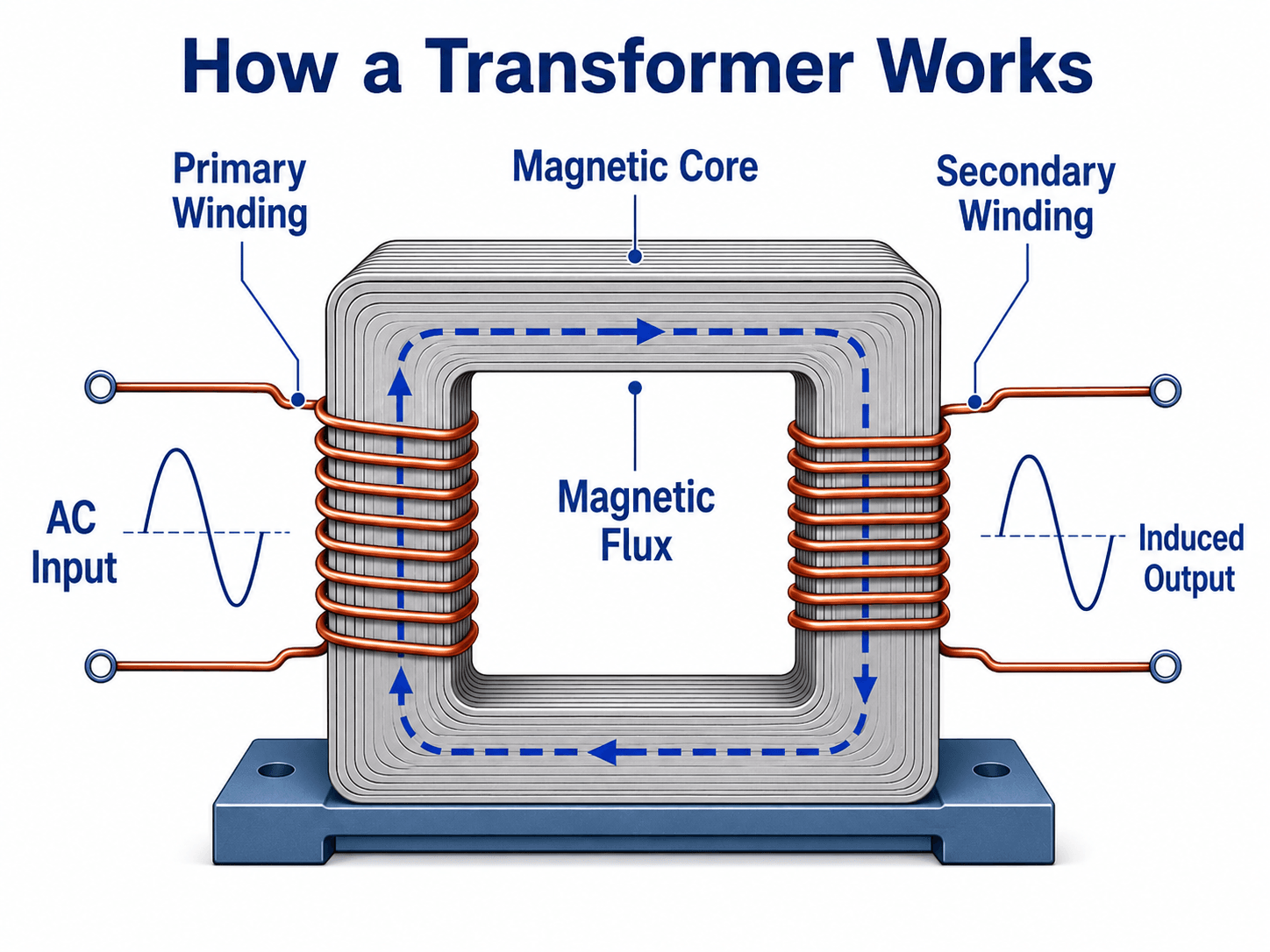
The diagram shows the core mechanism: AC energizes the primary winding, magnetic flux links the laminated core, and the secondary winding receives induced voltage. The windings are not normally connected by a direct conductor; energy transfers through the magnetic field.
What Is an Electrical Transformer?
An electrical transformer is an electromagnetic device with at least two windings linked by a magnetic core. The winding connected to the source is the primary winding, and the winding connected to the load is the secondary winding. When AC voltage is applied to the primary winding, it produces alternating magnetic flux in the core. That changing flux induces voltage in the secondary winding.
The transformer is one of the reasons modern power systems can operate economically over long distances. Power plants, renewable generation facilities, transmission substations, distribution networks, industrial facilities, and buildings all use transformers to match voltage levels to the job being performed.
A transformer does not create extra power. Ignoring losses, raising voltage lowers current for the same apparent power. In real equipment, the output power is always slightly less than the input power because of core losses, winding losses, leakage flux, and heat.
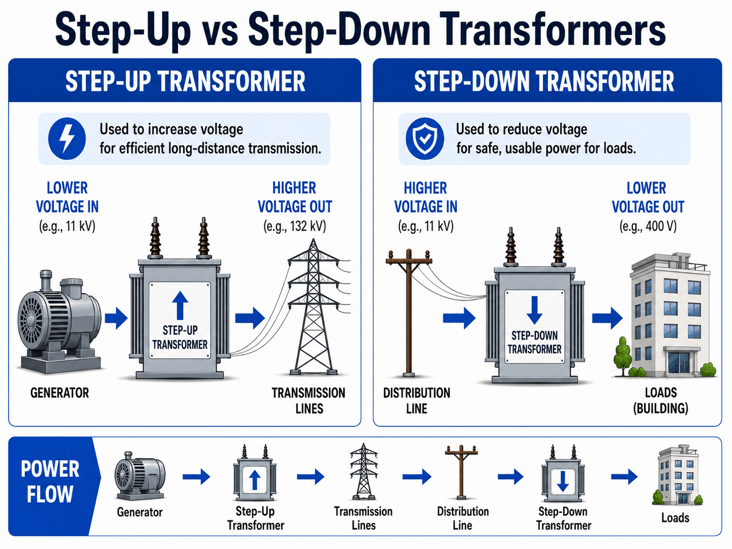
Step-Up vs Step-Down Transformers
The same transformer principle can either raise or lower voltage. A step-up transformer has more turns on the secondary winding than the primary winding. A step-down transformer has fewer turns on the secondary winding than the primary winding. In both cases, the voltage change is paired with an opposite current change for approximately the same power transfer.
| Transformer type | What it does | Common power system use | Engineering implication |
|---|---|---|---|
| Step-up transformer | Raises secondary voltage above primary voltage. | Generator step-up transformers and transmission substations. | Higher voltage reduces current for a given power transfer, which reduces line losses and conductor heating. |
| Step-down transformer | Lowers secondary voltage below primary voltage. | Distribution substations, pad-mounted transformers, service transformers, and building power systems. | Lower voltage makes power usable by equipment, panels, motors, lighting, and customer loads. |
| Isolation transformer | May keep the same voltage while magnetically separating circuits. | Industrial controls, test systems, sensitive equipment, and grounding-sensitive applications. | The main purpose is separation, noise reduction, or grounding control rather than voltage conversion. |
Where Transformers Are Used in Power Systems
Transformers appear throughout the power system because voltage is not one-size-fits-all. Generators, transmission lines, distribution feeders, industrial switchgear, building services, protection systems, and metering circuits each need voltage and current levels suited to their function.
| Power system location | Transformer role | Practical example |
|---|---|---|
| Generation | Steps generator voltage up to transmission voltage. | A generator step-up transformer connects a power plant or renewable facility to the high-voltage grid. |
| Transmission | Moves large amounts of power at high voltage and lower current. | Transmission substations transform between high-voltage levels for grid transfer and interconnection. |
| Distribution | Reduces voltage closer to customer loads. | Pad-mounted or pole-mounted transformers supply local circuits, homes, businesses, and small facilities. |
| Industrial power | Supplies facility voltage levels for motors, process equipment, switchboards, and control systems. | A medium-voltage transformer may step down utility service to 480 V equipment distribution. |
| Metering and protection | Scales current or voltage for instruments, meters, and relays. | Current transformers and voltage transformers provide safe measurement inputs to protective relays. |
| Isolation and controls | Separates circuits or provides control voltage. | Isolation transformers support sensitive equipment, test setups, and control panels. |
Transformer Equations and Turns Ratio
The ideal transformer equations are useful for understanding the relationship between winding turns, voltage, current, and apparent power. They are not a full design model, but they explain the basic behavior behind step-up and step-down operation.
The secondary-to-primary voltage ratio is approximately equal to the secondary-to-primary turns ratio. If the secondary winding has ten times as many turns as the primary winding, the ideal secondary voltage is about ten times the primary voltage.
Current moves in the opposite direction of voltage. A step-up transformer raises voltage but lowers secondary current for the same approximate apparent power. A step-down transformer lowers voltage but can supply higher secondary current.
Transformer capacity is usually expressed in volt-amperes or kilovolt-amperes. For three-phase systems, apparent power is commonly evaluated with \(S = \sqrt{3} V_{LL} I_L\), where \(V_{LL}\) is line-to-line voltage and \(I_L\) is line current.
Voltage regulation describes how much the secondary voltage changes from no-load to full-load conditions. Transformer impedance and load power factor strongly influence this value, which is why the same transformer can hold voltage well in one application and sag noticeably in another.
- \(V_p\) Primary voltage, usually in volts or kilovolts.
- \(V_s\) Secondary voltage delivered to the next circuit or load.
- \(N_p\) Number of primary winding turns.
- \(N_s\) Number of secondary winding turns.
- \(S\) Apparent power rating, commonly expressed in VA, kVA, or MVA.
These equations describe the ideal transformer relationship. Real transformer performance also depends on winding resistance, leakage reactance, core loss, excitation current, saturation, temperature, loading, and power factor.
Simple worked example
Suppose a single-phase transformer has 240 turns on the primary winding and 24 turns on the secondary winding. If the primary voltage is 2,400 V, the ideal secondary voltage is \(2,400 \times \frac{24}{240} = 240\) V. The transformer steps the voltage down by a 10:1 ratio.
Does a transformer change frequency?
A transformer changes voltage and current, but it does not change frequency. A 60 Hz primary system produces a 60 Hz secondary voltage under normal transformer operation. Frequency is set by the source system, not by the transformer turns ratio.
Main Parts and Types of Electrical Transformers
The basic transformer concept is simple, but practical transformers include parts that control insulation, heat, voltage adjustment, protection, and mechanical durability. The type of transformer selected depends on voltage level, load, environment, installation location, cooling method, and system function.
Main transformer components
| Component | Purpose | What engineers care about |
|---|---|---|
| Magnetic core | Provides a low-reluctance path for magnetic flux between windings. | Core material, saturation, no-load losses, noise, lamination quality, and operating frequency. |
| Primary and secondary windings | Carry current and establish the voltage transformation ratio. | Turns count, conductor size, insulation, heating, short-circuit forces, and winding resistance. |
| Insulation system | Separates energized parts and withstands voltage stress. | Temperature class, dielectric strength, moisture, aging, oil condition, and basic insulation level. |
| Tank or enclosure | Houses the transformer and protects internal components. | Indoor/outdoor rating, ventilation, fluid containment, corrosion, clearance, and access. |
| Tap changer | Allows limited voltage adjustment. | Tap range, energized or de-energized operation, voltage profile, and coordination with regulators. |
| Bushings and terminals | Provide insulated connections between internal windings and external circuits. | Voltage rating, creepage distance, contamination, mechanical condition, and connection integrity. |
Common types of electrical transformers
| Transformer type | Typical use | Practical selection note |
|---|---|---|
| Power transformer | Bulk power transfer at generation, transmission, or major substations. | Focus on MVA rating, impedance, cooling, insulation level, tap changer, protection, and reliability. |
| Distribution transformer | Local voltage reduction for customer or facility service. | Focus on service voltage, load diversity, losses, grounding, fusing, thermal loading, and maintainability. |
| Dry-type transformer | Indoor commercial, industrial, and building power applications. | Focus on ventilation, sound level, enclosure, temperature rise, and installation clearances. |
| Oil-filled transformer | Utility, substation, pad-mounted, and higher-capacity applications. | Focus on oil condition, leaks, cooling, containment, fire risk, and environmental requirements. |
| Autotransformer | Voltage adjustment where electrical isolation is not required. | Smaller and efficient for certain ratios, but it does not provide the same isolation as a two-winding transformer. |
| Current transformer | Scales current for metering and protective relays. | Ratio accuracy, burden, polarity, saturation, and protection class are critical. |
| Voltage transformer | Scales voltage for metering, controls, and relays. | Accuracy, burden, grounding, fuse protection, and insulation level affect measurement quality. |
Power transformer vs distribution transformer
| Feature | Power transformer | Distribution transformer |
|---|---|---|
| Main use | Bulk power transfer between major voltage levels. | Supplying local loads at usable distribution or service voltage. |
| Typical location | Generating stations, transmission substations, and large utility substations. | Distribution feeders, pads, poles, buildings, and local service points. |
| Loading pattern | Often planned around high-capacity grid transfer and contingency operation. | Often varies with customer demand, daily load shape, and seasonal load diversity. |
| Key concern | Reliability, MVA capacity, impedance, cooling, insulation, and protection. | Service voltage, losses, transformer loading, maintenance access, fusing, and customer reliability. |
Transformer Winding Connections
In three-phase power systems, winding connection matters almost as much as voltage ratio. Delta, wye, grounded-wye, and delta-wye configurations affect grounding, neutral availability, phase shift, harmonic behavior, and protection design.
| Connection | Where it appears | Why it matters |
|---|---|---|
| Delta | Primary or secondary windings in utility and industrial systems. | Can support certain phase-shift arrangements and provide a path for some circulating harmonic currents. |
| Wye | Transmission, distribution, and building power systems. | Provides a neutral point when the connection is accessible and supports line-to-neutral voltage use. |
| Grounded wye | Common in utility and facility distribution systems. | Supports grounding, line-to-neutral loads, and predictable ground-fault behavior when designed correctly. |
| Delta-wye | Common transformer bank and substation arrangement. | Introduces phase shift and grounding behavior that must be considered in protection, metering, and parallel operation. |
Transformer Losses, Efficiency, and Heat
Real transformers are efficient, but they are not lossless. Losses become heat, and heat affects insulation life, loading limits, oil condition, ventilation, and reliability. The most important practical distinction is between losses that exist whenever the transformer is energized and losses that increase with load current.
| Loss or behavior | Where it occurs | Why it matters in operation |
|---|---|---|
| Core loss | Magnetic core | Exists even at no load because the core is magnetized whenever voltage is applied. |
| Hysteresis loss | Magnetic material | Energy is lost as magnetic domains reverse direction each AC cycle. |
| Eddy current loss | Core laminations | Circulating currents in the core create heat; laminated cores reduce this effect. |
| Copper or winding loss | Primary and secondary windings | Increases with the square of current, so overheating risk rises quickly under overload. |
| Leakage flux | Flux path outside ideal coupling | Contributes to voltage drop, impedance, fault-current behavior, and regulation. |
| Inrush current | Core during energization | Can be much higher than normal load current and must be considered in protection settings. |
Efficiency compares useful output power to input power. In service, transformer efficiency depends on loading, power factor, core loss, winding loss, temperature, and operating voltage. A transformer can be very efficient at one loading point and less efficient when lightly loaded or heavily overloaded.
How to Read a Transformer Nameplate
A transformer nameplate is the practical bridge between theory and equipment. It tells engineers whether the transformer is suitable for a system voltage, phase, frequency, loading condition, fault-current study, protection scheme, cooling arrangement, and installation environment.
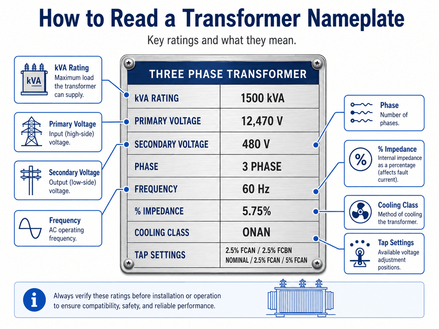
Example nameplate interpretation
A 1500 kVA, 12,470 V to 480 V, three-phase transformer can supply 480 V three-phase loads from a medium-voltage source when applied within its rated conditions. A 5.75% impedance affects both available fault current and voltage regulation, while an ONAN cooling class indicates oil natural, air natural cooling.
Why percent impedance matters
Percent impedance is one of the most important transformer nameplate values because it affects fault current, voltage regulation, and parallel operation. Lower impedance generally allows higher short-circuit current and better voltage stiffness. Higher impedance generally reduces fault current but can increase voltage drop under load.
| Nameplate item | What to look for | Why it matters |
|---|---|---|
| kVA or MVA rating | Maximum apparent power capacity under rated conditions. | Determines whether the transformer can support the connected load without excessive heating. |
| Primary and secondary voltage | Rated input and output voltage levels. | Confirms system compatibility and whether the transformer is being used as step-up or step-down equipment. |
| Phase and frequency | Single-phase or three-phase, normally at the intended system frequency. | Mismatch can cause incorrect voltage, overheating, poor performance, or unusable equipment. |
| Percent impedance | Transformer impedance expressed as a percentage of rated values. | Affects voltage regulation, short-circuit current, protection coordination, and parallel operation. |
| Cooling class | Cooling method such as dry-type ventilation or oil-filled natural/forced cooling. | Controls allowable loading and temperature rise under real operating conditions. |
| Tap settings | Available voltage adjustment positions. | Allows engineers or operators to correct voltage within a limited range without changing the transformer. |
Transformer Design Review Checklist
A transformer should not be evaluated from voltage ratio alone. Before a transformer is applied in a power system, engineers review loading, voltage class, fault current, cooling, protection, grounding, installation environment, and future load growth.
Start with the system voltage and load kVA. Confirm phase, frequency, and winding connection. Check impedance for fault-current and voltage-regulation studies. Review cooling and installation conditions. Then coordinate protection, grounding, taps, and maintenance access before approving the application.
| Design review check | What to look for | Why it matters |
|---|---|---|
| Load versus kVA rating | Expected demand, load diversity, motor starting, harmonics, and future growth. | Undersizing causes overheating and shortened life; oversizing can increase cost and no-load losses. |
| Voltage and taps | Primary voltage, secondary voltage, tap range, and expected feeder voltage variation. | Incorrect voltage can damage equipment, reduce motor torque, or create poor service voltage. |
| Percent impedance | Nameplate impedance and tolerance. | Controls available fault current, voltage drop under load, and compatibility for parallel transformers. |
| Thermal environment | Ambient temperature, ventilation, enclosure, sun exposure, altitude, and cooling class. | Transformer insulation life is strongly affected by temperature, especially during sustained overloads. |
| Protection and grounding | Fuses, breakers, relays, neutral grounding, surge protection, and coordination with upstream devices. | Protection must avoid nuisance trips while still clearing internal and external faults quickly enough. |
| Maintenance access | Clearances, oil sampling access, infrared inspection visibility, ventilation paths, and replacement logistics. | A transformer that is hard to inspect or replace can become a reliability and outage-planning problem. |
Engineering Judgment and Field Reality
Textbook transformer diagrams usually show perfect magnetic coupling, no resistance, no leakage flux, no heating, and no voltage drop. Real transformers operate inside a physical system. Load varies by hour and season, ambient temperature changes, cooling passages collect dust, oil can age, insulation weakens, and protection devices must tolerate energization without ignoring real faults.
In power systems work, transformer decisions often involve tradeoffs. Lower impedance can improve voltage regulation but increase available fault current. Higher impedance can reduce fault current but worsen voltage drop. Larger units can provide growth margin but may cost more and operate less efficiently when lightly loaded. Oil-filled units can handle high power well but introduce fluid containment, fire, and environmental considerations.
A transformer that is correct on paper can still perform poorly if it is installed in a hot enclosure, loaded with high harmonic currents, operated with incorrect taps, poorly ventilated, or protected with settings that do not account for inrush current and downstream fault behavior.
When the Ideal Transformer Model Breaks Down
The ideal transformer model is useful for learning, but it breaks down when the transformer is pushed outside the assumptions behind the simple equations. Real equipment must be reviewed for thermal limits, insulation stress, fault behavior, harmonics, saturation, voltage regulation, and installation conditions.
- Steady DC operation: a conventional transformer needs changing flux, so steady DC does not produce continuous transformer action and can drive the core toward saturation.
- Core saturation: overvoltage, incorrect frequency, DC offset, or energization conditions can saturate the core and cause high magnetizing current.
- Overloading: load current increases winding losses and temperature, which can accelerate insulation aging.
- Harmonic-rich loads: nonlinear loads can increase heating and require transformer derating or specialized designs.
- Incorrect impedance assumptions: fault-current studies and voltage-regulation estimates can be wrong if nameplate impedance or system configuration is not used correctly.
Common Transformer Mistakes and Practical Checks
Many transformer mistakes come from treating a transformer as only a voltage-ratio device. In real power systems, the transformer is also a thermal device, an impedance element, an insulation system, a protection zone, and a maintenance asset.
| Question or mistake | Practical answer | Why it matters |
|---|---|---|
| Does a transformer change frequency? | No. It changes voltage and current, but the secondary frequency follows the primary system frequency. | Frequency-sensitive equipment must match the source system, not just the transformer voltage. |
| Does a transformer work on DC? | Not continuously in a conventional transformer. | Steady DC does not create the changing flux needed for sustained transformer action. |
| Does a transformer create power? | No. Output power is less than input power because real transformers have losses. | Voltage conversion does not eliminate conservation of energy or thermal limits. |
| Why use high voltage transmission? | Higher voltage lowers current for the same power transfer. | Lower current reduces conductor losses and heating over long distances. |
- Confusing kW with kVA: transformer loading is rated by apparent power, so power factor affects how much real power can be supplied.
- Ignoring percent impedance: impedance affects both voltage regulation and available short-circuit current.
- Assuming voltage ratio is enough: phase, frequency, grounding, cooling, taps, insulation level, and environment must also match the application.
- Overlooking inrush current: energizing a transformer can produce high transient current that may affect protection settings.
- Using ideal equations for final design: ideal equations explain relationships but do not replace a nameplate review, project specifications, or equipment data.
Do not assume a transformer is acceptable just because the primary and secondary voltages match. Always check kVA rating, impedance, phase, frequency, winding connection, cooling, tap settings, grounding arrangement, and protection requirements.
Useful References and Design Context
Transformer design and application can involve manufacturer data, utility standards, owner specifications, protection studies, installation codes, and industry standards. For a concise industry definition and product context, the National Electrical Manufacturers Association provides a useful reference point.
- NEMA transformer overview: review NEMA’s overview of electrical transformers for a concise description of transformers as static electrical machines used to increase or decrease AC voltages in electric power applications.
- Project-specific criteria: final transformer selection may also be controlled by utility interconnection rules, owner standards, electrical codes, equipment specifications, and site conditions.
- Engineering use: engineers use transformer references alongside nameplate data, load studies, short-circuit studies, protection coordination, and thermal review before applying equipment in a real system.
Frequently Asked Questions
A transformer is a static AC electrical device that transfers energy between circuits through electromagnetic induction. In power systems, transformers are mainly used to raise voltage for efficient transmission or lower voltage for safe distribution and equipment use.
A standard transformer needs changing magnetic flux to induce voltage in the secondary winding. Alternating current naturally creates that changing flux, while steady DC does not after the initial switching moment, so a conventional transformer cannot continuously transform steady DC voltage.
No. A transformer changes voltage and current, but it does not change frequency. A 60 Hz primary voltage produces a 60 Hz secondary voltage under normal transformer operation.
A step-up transformer has more secondary turns than primary turns, so it raises voltage and lowers current for the same approximate power transfer. A step-down transformer has fewer secondary turns than primary turns, so it lowers voltage and raises available current for downstream loads.
kVA is the transformer apparent power rating. It describes the voltage-current capacity the transformer can carry under rated conditions, regardless of the load power factor. Engineers use kVA because transformer heating depends strongly on current and losses, not only on real power in kW.
Summary and Next Steps
Electrical transformers are one of the most important pieces of power system equipment because they allow voltage to be changed without changing frequency. By stepping voltage up for transmission and down for distribution, transformers help power systems move energy efficiently from generation sources to usable loads.
The key concepts are magnetic induction, turns ratio, current ratio, kVA rating, impedance, voltage regulation, losses, heat, cooling, winding connection, and nameplate interpretation. In engineering practice, a transformer is not just a voltage conversion device; it is also a thermal, insulation, protection, and reliability asset.
Where to go next
Continue your learning path with related Turn2Engineering resources.
-
Voltage Regulation
Learn how transformer impedance and load changes affect delivered voltage across a power system.
-
Protective Relays
Explore how protection systems detect abnormal conditions and help isolate transformer, feeder, and equipment faults.
-
Switchgear
See how switching and protective equipment operates around transformers and other power system assets.