Key Takeaways
- Definition: Beam deflection formulas relate load, span, stiffness, and support conditions to the vertical displacement of a beam under applied loading.
- Main use: Engineers use them to check serviceability, alignment, vibration sensitivity, and whether a member will feel or look too flexible in use.
- Watch for: Support condition mistakes and wrong moment of inertia values can swing the answer dramatically, even when the arithmetic is correct.
- Outcome: After reading, you should know which beam deflection expression fits a common case, what each term means, and how to sanity-check the result.
Table of Contents
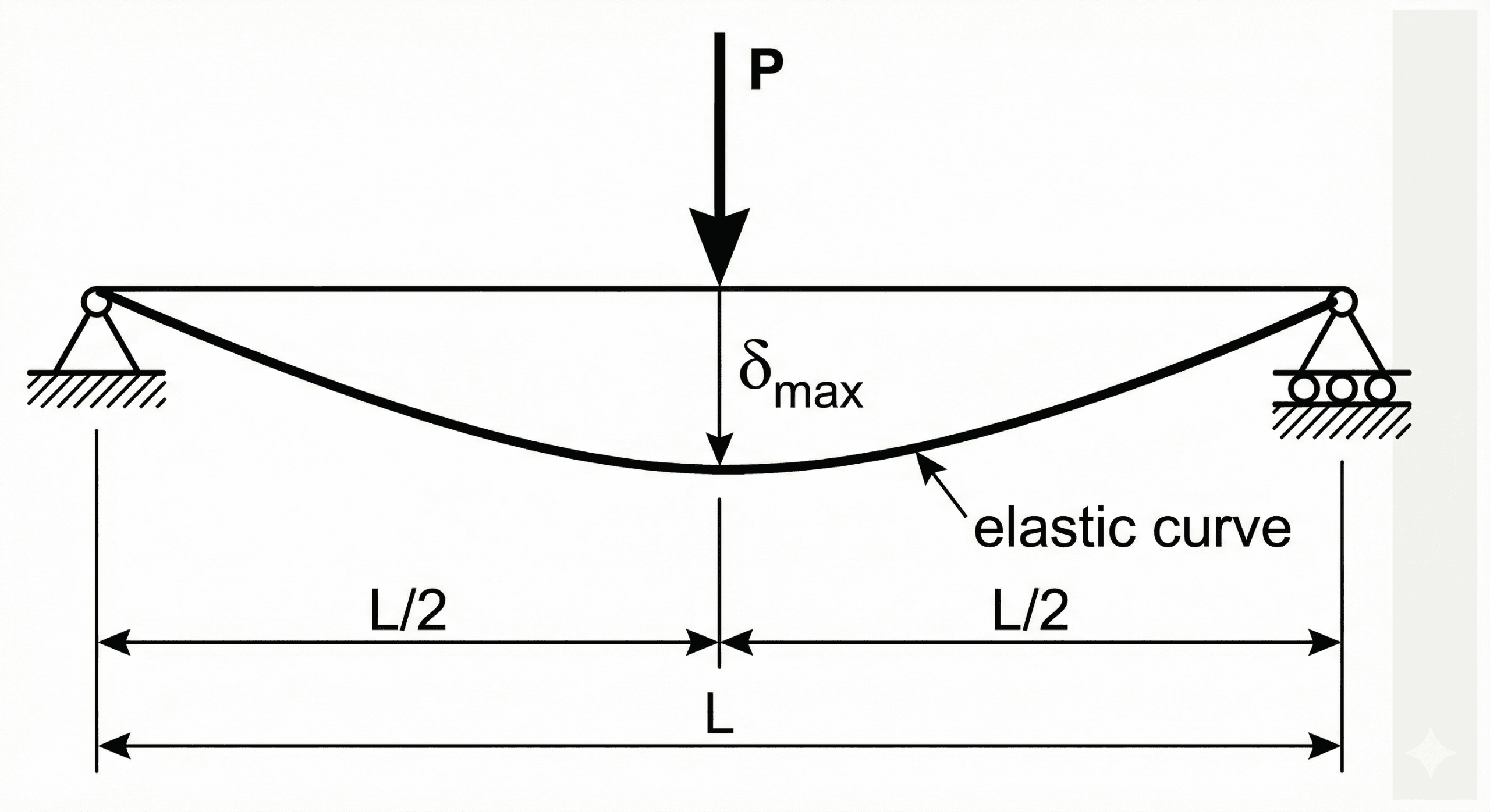
Beam deflection example showing span, loading, and maximum displacement
Beam deflection formulas relate load, span, stiffness, and support conditions to the vertical displacement of a beam under service or test loading.
The first thing to notice is that deflection is not controlled by load alone. Long spans deflect much more than short spans, and a beam with a larger moment of inertia or higher modulus will stay significantly stiffer under the same loading.
What is the beam deflection formula?
The beam deflection formula is a family of closed-form expressions used to estimate how far a beam moves from its original position when it is loaded. In practice, engineers are usually asking one of three questions: how much will the beam sag, is that amount acceptable for serviceability, and what change to span, material, or section stiffness would reduce that movement?
The underlying mechanics come from elastic beam theory. Instead of treating the beam as a rigid member, the formula recognizes that a real beam bends under load. The amount of bending depends on the load pattern, the support condition, the span \(L\), the material stiffness \(E\), and the cross-sectional stiffness \(I\).
This is why beam deflection formulas are used so heavily in building floors, roof members, machine frames, shafts, test rigs, conveyor supports, and structural serviceability checks. Stress tells you whether the beam is strong enough; deflection tells you whether it is stiff enough.
The beam deflection formula
There is no single universal beam deflection equation that covers every support and loading case in one compact algebraic form. The general relationship behind most small-deflection beam problems is:
This equation says that beam curvature is driven by bending moment and resisted by flexural rigidity \(EI\). Once you know the moment function \(M(x)\), you integrate with the proper boundary conditions to obtain slope and deflection.
For quick engineering checks, most people use closed-form case equations instead of re-integrating the differential equation every time. One of the most common is the maximum deflection for a simply supported beam carrying a uniform load:
Another high-frequency case is the maximum deflection for a simply supported beam with a concentrated load at midspan:
Those powers of \(L\) are the real story. Deflection grows very rapidly with span, which is why long members often fail serviceability well before they approach material strength limits.
Variables and units
Beam deflection problems are easy to misread because several variables look familiar but carry very different physical meaning. The best habit is to define the geometry, loading, support condition, and bending axis before plugging in a formula.
- \( \delta \) Deflection, usually the maximum vertical displacement of the beam. Common units: m, mm, ft, or in.
- \( E \) Elastic modulus of the material. Common units: Pa, GPa, psi, or ksi.
- \( I \) Second moment of area about the bending axis. Common units: m\(^4\), mm\(^4\), or in\(^4\).
- \( L \) Span length between supports or effective points of restraint. Common units: m, mm, ft, or in.
- \( w \) Distributed load intensity, such as N/m, kN/m, lb/ft, or kip/ft.
- \( P \) Concentrated point load, such as N, kN, lb, or kip.
Keep the load, span, modulus, and inertia in one coherent unit system. A correct formula with mixed inches, feet, ksi, and in\(^4\) can still produce a wildly wrong deflection.
For ordinary building beams under service loads, maximum elastic deflection is often a small fraction of the span, not a large percentage of it. If your answer is several inches on a short beam, revisit your units and support assumptions.
| Variable | Meaning | SI units | US customary units | Typical engineering role | Notes |
|---|---|---|---|---|---|
| \(E\) | Elastic modulus | Pa or GPa | psi or ksi | Material stiffness | Higher \(E\) means less deflection |
| \(I\) | Second moment of area | m\(^4\), mm\(^4\) | in\(^4\) | Section stiffness | About the correct bending axis only |
| \(L\) | Span length | m, mm | ft, in | Geometric amplifier | Usually the most sensitive input |
| \(w\) | Uniform load | N/m, kN/m | lb/ft, kip/ft | Distributed loading case | Match to the selected formula |
| \(P\) | Point load | N, kN | lb, kip | Concentrated loading case | Location matters, not just magnitude |
How to rearrange the beam deflection formula
In design work, engineers often know the allowable deflection and need to solve backward for stiffness rather than forward for displacement. That makes rearrangement useful for selecting a section, checking whether a material upgrade helps enough, or estimating the stiffness penalty of a longer span.
Starting from the common simply supported uniform-load case,
you can rearrange for required flexural rigidity:
If you already know the material, you can then solve for the required section inertia:
When solving backward, verify that the resulting \(I\) is about the loaded bending axis and not the weak axis by accident. This is one of the fastest ways to understate real deflection.
Worked example
Simply supported steel beam with a uniform load
Suppose a simply supported steel beam spans \(6 \, \text{m}\) and carries a service uniform load of \(8 \, \text{kN/m}\). The beam has \(E = 200 \, \text{GPa}\) and \(I = 85 \times 10^{-6} \, \text{m}^4\). Estimate the maximum elastic deflection.
For a simply supported beam with uniform load,
Convert the variables into a consistent SI set:
- \(w = 8 \, \text{kN/m} = 8000 \, \text{N/m}\)
- \(L = 6 \, \text{m}\)
- \(E = 200 \times 10^9 \, \text{Pa}\)
- \(I = 85 \times 10^{-6} \, \text{m}^4\)
The predicted maximum deflection is about \(7.6 \, \text{mm}\). Physically, that is a small but noticeable downward movement, and whether it is acceptable depends on the project limit. On a \(6 \, \text{m}\) span, this corresponds to about \(L/787\), which would satisfy many ordinary serviceability situations.
The answer matters less as a standalone number than as a ratio to allowable movement, architectural tolerance, facade sensitivity, ponding risk, or vibration comfort criteria.
Assumptions behind the equation
Simple beam deflection formulas look compact because they package several assumptions into a neat closed form. Those assumptions are often acceptable for preliminary design, exam problems, and many serviceability checks, but they still need to be understood.
- 1 The beam remains in the linear elastic range, so stiffness does not change from yielding, cracking, or permanent deformation.
- 2 Deflections are small enough that geometry changes do not significantly alter internal force paths.
- 3 The member is prismatic, meaning \(E\) and \(I\) are constant or treated as constant over the span for the selected expression.
- 4 Plane sections are assumed to remain plane, which is the usual Euler-Bernoulli beam assumption.
Neglected factors
- Shear deformation, which can matter in short, deep, or soft-core members.
- Composite action uncertainty, slip, cracking, or partial interaction in built-up systems.
- Actual support flexibility, settlement, rotation, and imperfect restraint.
- Time-dependent effects such as creep, especially in wood and concrete.
- Load redistribution in frames, slabs, and multi-member systems that do not behave like isolated single beams.
Engineering judgment and field reality
In the field, the most important beam deflection question is rarely “what is the exact theoretical number?” It is usually “is this member stiff enough for what the building, machine, or support system needs to do?” A mathematically correct deflection can still be unacceptable if finishes crack, doors bind, drains stop working, vibration becomes noticeable, or users simply perceive the beam as too flexible.
Real beams often see stiffness reductions from bolt slip, connection flexibility, cracking, material variability, construction tolerances, or partially composite behavior. The textbook equation is still useful, but it should not be mistaken for a full system model.
If your serviceability answer looks surprisingly good, try stress-testing the model by asking whether the support condition is too optimistic or whether the section inertia came from the wrong axis or wrong built-up assumption.
Common mistakes and engineering checks
- Using the right equation for the wrong support condition.
- Using a moment of inertia about the wrong bending axis.
- Forgetting that distributed load and point load formulas are different cases.
- Mixing ft with in or ksi with psi while leaving \(I\) in in\(^4\).
- Checking strength only and never checking stiffness or serviceability.
- Treating an isolated beam equation as if it fully represents a frame, slab, or composite floor system.
Ask whether the beam becomes more or less flexible in the direction your formula predicts. If a longer span, lower \(E\), or smaller \(I\) does not increase deflection in your model, something is wrong.
| Check item | What to verify | Why it matters |
|---|---|---|
| Support condition | Simply supported, cantilever, fixed-fixed, or another case | The coefficient can change dramatically |
| Axis of bending | Correct \(I\) about the loaded axis | Weak-axis mistakes can underpredict deflection |
| Units | All terms in one coherent system | Mixed units are the most common arithmetic failure |
| Magnitude | Result versus span-based reasonableness | Catches hidden input or formula selection errors |
Frequently asked questions
There is not one single beam deflection formula for every case. The general elastic-beam relationship is \(EI \, d^2y/dx^2 = M(x)\), while practical design work usually uses case-specific maximum-deflection equations such as \( \delta_{\max} = 5wL^4/(384EI) \) for a simply supported beam with a uniform load.
\(E\) is the elastic modulus of the beam material, which measures material stiffness. \(I\) is the second moment of area of the cross-section about the bending axis, which measures geometric resistance to bending. Together, \(EI\) is the flexural rigidity.
You reduce beam deflection by shortening the span, reducing the load, increasing the section moment of inertia, choosing a stiffer material with higher \(E\), or modifying support conditions so the beam behaves more rigidly.
Simple beam formulas become less reliable when support conditions are uncertain, deflections are no longer small, shear deformation matters, cracking or yielding changes stiffness, or the real member behaves as part of a frame, slab, composite system, or plate rather than as an isolated prismatic beam.
Summary and next steps
Beam deflection formulas are stiffness tools. They help you translate load, span, material properties, and section geometry into a usable estimate of movement. In most real projects, that movement matters because serviceability controls usability, appearance, drainage, alignment, vibration, and owner confidence in the structure.
The most important engineering habits are choosing the correct loading and support case, using the right \(I\) value about the correct axis, keeping units consistent, and checking whether the result makes physical sense before trusting it.
Where to go next
Continue your learning path with these next steps.
-
Prerequisite: Moment of Inertia Calculator
Build or verify the section property that directly controls geometric stiffness in beam deflection problems.
-
Apply it: Beam Calculator
Use the formula in a more complete beam workflow with different loading and support scenarios.
-
Advanced: Euler’s Formula
Extend stiffness concepts into stability and buckling, where the same flexural rigidity term \(EI\) remains central.