Key Takeaways
- Core idea: Power distribution is the local delivery stage of the electric grid, carrying electricity from substations to end users.
- Engineering use: Distribution design focuses on feeders, transformers, voltage levels, protection, switching, losses, and service reliability.
- What controls it: Load density, feeder length, voltage drop, fault current, topology, phase balance, and future load growth drive distribution decisions.
- Practical check: A distribution system should be reviewed for capacity, voltage quality, protective coordination, restoration options, and field access.
Table of Contents
Introduction
Power distribution is the local delivery stage of the electric grid, carrying electricity from substations to the homes, businesses, and industrial equipment that actually use it. It includes feeders, transformers, switches, protection devices, meters, and service connections, and it is where many real-world outage, voltage, reliability, and load-growth problems appear.
How Power Distribution Works
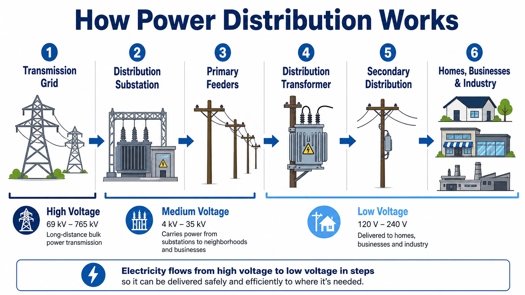
Read the diagram from left to right. Distribution starts where bulk power is stepped down at a substation and ends where secondary service conductors deliver usable voltage to customer loads.
What Is Power Distribution?
Power distribution is the final delivery network between the bulk electric grid and the customer. After electricity is generated and transmitted over long distances, it reaches a distribution substation where voltage is reduced and sent through local feeders. Those feeders branch into laterals, transformers, secondary circuits, and service connections that supply individual buildings.
In engineering terms, distribution is not just “wires to houses.” It is a coordinated system of conductors, transformers, switches, protective devices, voltage-control equipment, communication systems, and operating procedures. A good distribution system must deliver enough capacity, maintain acceptable voltage, isolate faults quickly, and remain flexible as loads change.
In utility engineering, power distribution usually means feeders, transformers, and service connections between substations and customers. Inside a building, power distribution usually refers to switchgear, panelboards, transformers, breakers, busway, and branch circuits that deliver power after the service entrance.
Power Transmission vs. Power Distribution
The easiest way to understand the difference is to compare the grid to transportation infrastructure. Transmission is like the interstate highway system: high-capacity, long-distance, and designed to move bulk energy efficiently. Distribution is like the local street network: lower voltage, more branches, and closer to the end user.
| Category | Power Transmission | Power Distribution |
|---|---|---|
| Primary purpose | Move large amounts of power over long distances. | Deliver electricity locally to homes, businesses, and industrial facilities. |
| Typical voltage level | High voltage, often tens to hundreds of kilovolts. | Medium voltage on primary feeders and low voltage near customers. |
| Common equipment | Transmission towers, high-voltage lines, breakers, and bulk substations. | Distribution substations, feeders, transformers, reclosers, fuses, switches, regulators, and service conductors. |
| Engineering focus | Bulk transfer capacity, grid stability, right-of-way, and interconnection. | Voltage regulation, reliability, protection coordination, load growth, losses, and customer service. |
Simple One-Line View of Power Distribution
A simplified one-line view helps show how power moves from the upstream grid to the customer. Each step changes the voltage level, protection zone, equipment type, or responsibility boundary.
Transmission Line → Distribution Substation → Primary Feeder → Lateral → Distribution Transformer → Secondary Service → Customer Load
| Step | What changes | Why it matters |
|---|---|---|
| Distribution substation | Voltage is stepped down from transmission or subtransmission level to primary distribution level. | This creates the source point for local feeders and establishes protection zones. |
| Primary feeder | Medium-voltage power moves through the local service area. | Feeder length, conductor size, and load distribution affect voltage drop and losses. |
| Lateral | Branches serve smaller neighborhoods, streets, or customer groups. | Laterals allow smaller sections to be isolated with fuses or sectionalizing devices. |
| Distribution transformer | Medium voltage is stepped down to utilization voltage. | This is the key transition between primary distribution and customer secondary service. |
| Secondary service | Low-voltage conductors deliver power to the customer. | Secondary runs should be short enough to control voltage drop and conductor size. |
Power Distribution Voltage Levels and Equipment Ranges
Voltage levels vary by utility, country, system age, and customer type, but the engineering logic is consistent: use higher voltage to move power efficiently, then step voltage down as the system gets closer to end users. The values below are typical North American examples, not universal limits.
| Distribution stage | Typical range or example | Common equipment | What it means |
|---|---|---|---|
| Subtransmission | Often about 35 kV to 138 kV | Subtransmission lines, regional substations, high-voltage breakers | Transfers power from the transmission network toward distribution substations. |
| Primary distribution | Often about 4 kV to 35 kV | Feeders, laterals, reclosers, fuses, regulators, capacitor banks | Forms the main local distribution backbone leaving the substation. |
| Distribution transformer | Common service-scale transformers may range from small residential units to larger commercial units | Pole-mounted transformers, pad-mounted transformers, vault transformers | Steps primary voltage down to customer utilization voltage. |
| Secondary distribution | Examples include 120/240 V, 208Y/120 V, and 480Y/277 V | Secondary conductors, service drops, service laterals, meters | Delivers usable voltage to residential, commercial, and industrial loads. |
If a conductor is carrying a large amount of power at low voltage over a long distance, current and voltage drop become major problems. That is one reason distribution systems keep power at medium voltage until it is close to the customer.
Main Components of a Power Distribution System
A distribution system is built from several layers of equipment. Each layer performs a different job, from stepping voltage down to detecting faults and connecting individual customers.
| Component | What it does | Engineering implication |
|---|---|---|
| Distribution substation | Receives power from the transmission or subtransmission system and steps it down for local feeders. | Sets the source capacity, feeder voltage, protection zones, and switching arrangement for a service area. |
| Primary feeder | Carries medium-voltage power away from the substation. | Feeder length, conductor size, and load distribution affect voltage drop, losses, and reliability. |
| Lateral | Branches from the main feeder to serve smaller groups of customers. | Laterals often use fuses or sectionalizing devices to limit the number of customers affected by a fault. |
| Distribution transformer | Steps medium voltage down to customer utilization voltage. | Transformer sizing must account for connected load, diversity, thermal loading, and future growth. |
| Recloser | Trips and automatically recloses after temporary faults. | Improves reliability when faults are temporary, such as tree contact or lightning-related disturbances. |
| Fuse cutout | Disconnects a faulted lateral, transformer, or small circuit section. | Must coordinate with upstream devices so the smallest practical section is isolated. |
| Voltage regulator | Adjusts feeder voltage to stay within acceptable limits. | Long feeders, changing load, solar backfeed, and motor starts can require active voltage control. |
| Capacitor bank | Supplies reactive power support and helps improve voltage and power factor. | Placement and switching must be reviewed to avoid overvoltage, resonance, or poor power quality. |
Distribution Feeders, Laterals, and Service Connections
A distribution feeder is the main medium-voltage circuit leaving a distribution substation. It may include a main trunk, branch laterals, protective devices, voltage-control equipment, transformers, and switching points. Feeders are one of the most important pieces of the distribution system because they determine how power is routed through a local service area.
Feeder trunk
The feeder trunk is the main path that carries the largest portion of the feeder load. It is commonly three-phase and may include reclosers, switches, regulators, and capacitor banks depending on length and loading.
Laterals
Laterals branch off the main feeder to serve smaller groups of loads. They may be single-phase, two-phase, or three-phase depending on the customers served. Fuses are often used on laterals so a fault on a smaller branch does not interrupt the entire feeder.
Service drops and service laterals
The final connection to a customer may be an overhead service drop or an underground service lateral. This is the last link between the utility distribution system and the customer service equipment.
Primary and Secondary Distribution
Distribution systems are commonly described as primary and secondary. Primary distribution is the medium-voltage portion that leaves the substation and feeds neighborhoods, commercial areas, or industrial sites. Secondary distribution is the low-voltage portion after a distribution transformer.
Primary distribution
Primary feeders usually operate at medium-voltage levels such as 4 kV to 35 kV, depending on the utility and region. These feeders are designed to carry power efficiently across a local area while limiting current, conductor size, and losses compared with low-voltage delivery over the same distance.
Secondary distribution
Secondary circuits operate at utilization voltage and are much closer to the customer. Residential systems often use 120/240 V split-phase service, while commercial buildings may use 208Y/120 V or 480Y/277 V service. The exact voltage depends on the service type, building load, equipment, and utility standards.
Long low-voltage runs create high current, larger voltage drop, and larger conductors. That is why distribution systems carry power at medium voltage as long as practical before stepping down near the customer.
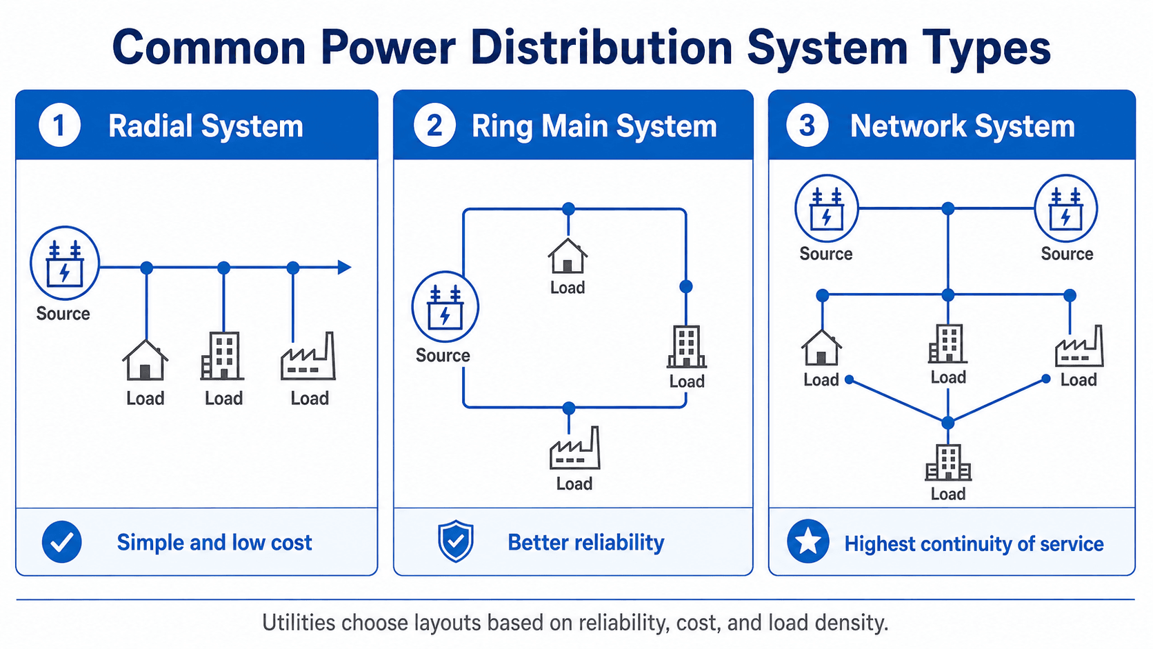
Common Power Distribution System Types
Distribution layout affects reliability, cost, switching flexibility, and how many customers lose power during a fault. The common conceptual layouts include radial, loop or ring main, parallel feeder, and network systems.
| System type | Best fit | Main advantage | Main limitation |
|---|---|---|---|
| Radial distribution | Residential, rural, and lower-density areas. | Simple, economical, and easy to operate. | A single upstream fault can interrupt downstream customers. |
| Ring main or loop distribution | Suburban, campus, and commercial areas needing better reliability. | Allows alternate feed paths and improved switching flexibility. | Requires more switching equipment and careful operating procedures. |
| Parallel feeder system | Critical loads or customers needing redundancy. | Multiple feeders can serve the same load or area. | More expensive and more complex to protect and operate. |
| Network distribution | Dense urban areas, critical facilities, and high-load-density districts. | Provides high service continuity with multiple sources and interconnected paths. | More expensive, complex, and dependent on specialized protection schemes. |
Overhead vs. Underground Distribution
Power distribution can be built overhead on poles or underground in ducts, conduits, trenches, or direct-buried cable systems. The choice affects cost, aesthetics, fault exposure, repair time, and long-term maintenance.
| Distribution type | Advantages | Tradeoffs |
|---|---|---|
| Overhead distribution | Lower initial cost, easier inspection, faster access for repair, and simpler expansion. | More exposed to wind, trees, lightning, ice, vehicle impacts, and animal contact. |
| Underground distribution | Better aesthetics, less exposure to wind and vegetation, and improved public-space clearance. | Higher installation cost, harder fault location, more complex repair, and more sensitivity to water intrusion or cable aging. |
Overhead systems are often preferred where cost and repair access are major priorities. Underground systems are common in dense urban areas, campuses, new subdivisions, and locations where appearance or overhead exposure is a concern.
Residential, Commercial, and Industrial Power Distribution
Distribution systems serve many types of loads, and the service arrangement changes with the customer. A house, a small store, a hospital, and a factory may all be connected to the same broad distribution system, but their voltage, phase, transformer, and reliability needs can be very different.
| Customer type | Common service characteristics | Practical difference |
|---|---|---|
| Residential | Often 120/240 V split-phase service in North America. | Many small loads, short secondary runs, and many individual service connections. |
| Small commercial | May use 208Y/120 V or 480Y/277 V depending on equipment and utility service. | Lighting, HVAC, panels, elevators, kitchens, and small motors may drive service needs. |
| Industrial | May use larger three-phase service or medium-voltage service with customer-owned transformers. | Large motors, process loads, switchgear, power quality, and reliability requirements become more important. |
| Critical facilities | May need redundant feeds, generators, UPS systems, or network service. | Hospitals, data centers, and mission-critical facilities often need stronger continuity planning. |
Voltage Regulation, Volt-VAR Control, and Power Quality
A distribution system must do more than stay energized. It must maintain voltage within an acceptable range while loads change throughout the day. Motors starting, large HVAC loads, long feeders, poor power factor, rooftop solar, and electric vehicle charging can all affect feeder voltage.
Voltage drop
Voltage drop occurs when current flows through conductor impedance. As feeders get longer or more heavily loaded, voltage at the far end can fall. Engineers manage this with conductor sizing, transformer placement, feeder configuration, voltage regulators, capacitor banks, and load balancing.
This simplified voltage-drop relationship shows why current, conductor resistance, reactance, and power factor all matter. It is not a replacement for detailed feeder modeling, but it explains why long, heavily loaded feeders need careful voltage review.
Volt-VAR control
Volt-VAR control coordinates voltage and reactive power on a distribution feeder. Voltage regulators, load tap changers, capacitor banks, and smart inverters may be used to support voltage, reduce unnecessary reactive current, and improve feeder performance under changing load and generation conditions.
Power quality
Power quality includes voltage sags, swells, flicker, harmonics, unbalance, and interruptions. These issues are especially important for sensitive electronics, variable frequency drives, data centers, industrial processes, and facilities with large motor loads.
Power Distribution Losses
Distribution losses occur in conductors, transformers, connectors, and other equipment. Some losses are unavoidable, but they increase when current is high, feeders are long, phases are unbalanced, power factor is poor, or equipment is overloaded.
The equation shows why higher distribution voltage is useful. For the same amount of power, a higher voltage generally allows lower current. Lower current reduces conductor losses because resistive losses increase with the square of current.
| Loss driver | Why it matters | Engineering response |
|---|---|---|
| High current | Increases \(I^2R\) losses and heating. | Review voltage level, conductor size, load distribution, and transformer placement. |
| Poor power factor | Can increase current for the same useful real power. | Use capacitor banks, power factor correction, or load-side mitigation where appropriate. |
| Long feeders | Increase conductor impedance and voltage drop. | Consider feeder reinforcement, voltage regulation, sectionalizing, or new source points. |
| Unbalanced phases | Can overload one phase and increase neutral current. | Review phase loading and rebalance single-phase laterals where practical. |
Protection, Switching, and Reliability
Distribution protection is designed to detect abnormal current, isolate the faulted section, and keep as much of the system energized as practical. Unlike a simple circuit, real distribution feeders may include many branches, transformers, fuses, reclosers, switches, and customer loads.
- Fuses isolate small laterals, transformers, or branch sections.
- Reclosers interrupt faults and automatically reclose for temporary disturbances.
- Sectionalizers work with upstream devices to isolate faulted sections after fault current has been counted.
- Switches allow planned maintenance, load transfers, and restoration after outages.
- Relays and breakers protect substation feeders and larger distribution circuits.
A reliable distribution system is not only about having stronger equipment. It also depends on whether devices coordinate correctly, whether alternate feeds exist, and whether crews or automation can sectionalize faults quickly.
Power Distribution Design Review Checklist
A distribution review should connect the electrical design to real operating conditions. The goal is to confirm that the system can serve normal load, tolerate reasonable future growth, maintain voltage, and isolate faults without unnecessary customer interruptions.
Start with the load forecast, select or confirm the service voltage, map the feeder and transformer arrangement, check voltage drop and thermal loading, review fault current and protective device coordination, then confirm switching options for maintenance and outage restoration.
| Check or decision | What to look for | Why it matters |
|---|---|---|
| Load forecast | Connected load, diversified demand, motor load, EV charging, future expansion, and seasonal peaks. | Undersized feeders and transformers can overheat or create poor voltage during peak demand. |
| Feeder length and conductor size | Long runs, high current, conductor impedance, and end-of-line voltage. | Voltage drop and losses increase with distance and loading. |
| Transformer placement | Distance to loads, available fault current, service voltage, access, and clearance requirements. | Transformer location affects secondary voltage drop, maintenance access, and customer service reliability. |
| Protection coordination | Fuse sizes, recloser settings, breaker curves, transformer protection, and downstream selectivity. | Good coordination isolates the smallest practical faulted section instead of tripping a larger area. |
| Switching flexibility | Tie switches, loop feeds, sectionalizing points, and alternate restoration paths. | Switching options can reduce outage duration during faults, maintenance, and equipment replacement. |
| Power quality risk | Large motors, nonlinear loads, solar inverters, capacitor banks, flicker-sensitive loads, and harmonics. | Distribution design must support both capacity and usable voltage quality. |
Common Failure Modes and Troubleshooting Clues
Distribution problems often show up as visible customer symptoms before the root cause is obvious. A troubleshooting mindset connects the symptom to the likely part of the distribution system.
| Failure mode | Likely cause | What users notice | Engineering response |
|---|---|---|---|
| Voltage sag | Motor starting, high load, long feeder, or weak source. | Lights dim, contactors chatter, or equipment trips. | Review feeder voltage profile, regulator settings, conductor size, and motor starting impact. |
| Blown fuse | Faulted lateral, transformer fault, tree contact, or animal contact. | Localized outage downstream of a branch or transformer. | Inspect the downstream section before refusing or restoring service. |
| Recloser operation | Temporary fault from lightning, vegetation, wildlife, or line contact. | Momentary blink or short interruption. | Review event history and identify repeated temporary fault locations. |
| Transformer overload | Load growth, poor diversity assumptions, or undersized equipment. | Low voltage, hot transformer, nuisance interruptions, or reduced equipment life. | Perform load study and consider transformer replacement, load transfer, or service upgrade. |
| Underground cable fault | Aging insulation, moisture intrusion, dig-in damage, or splice failure. | Underground outage that may not be visually obvious. | Fault locate, isolate, test, splice, or replace the affected cable section. |
| Harmonic distortion | Nonlinear loads, variable frequency drives, rectifiers, or inverter-based equipment. | Heating, nuisance trips, transformer noise, or sensitive equipment issues. | Perform a power quality study and review filtering, transformer loading, and grounding. |
Modern Distribution Grid Challenges
Distribution systems were traditionally designed for one-way power flow: from the substation to the customer. That assumption is changing. Rooftop solar, batteries, electric vehicles, smart inverters, demand response, and microgrids can all interact with local feeders in ways that change voltage, loading, protection, and operations.
Distributed energy resources
Solar, batteries, and customer-owned generation can reduce net load at one moment and export power at another. This can create reverse power flow, voltage rise, protection sensitivity issues, and new coordination challenges.
Electrification and load growth
Electric vehicles, heat pumps, data centers, and industrial electrification can increase local demand faster than legacy feeders were designed to handle. Planning must consider not just present load, but where future load will appear and how quickly it may grow.
Engineering Judgment and Field Reality
Distribution diagrams often look clean, but field systems are messy. Real feeders may have decades of additions, mixed conductor sizes, older transformers, vegetation exposure, load transfers, customer-owned generation, and switching practices that are not obvious from a simplified one-line diagram.
The weak point in a distribution area is not always the largest piece of equipment. It may be a long lateral, an old transformer, a fuse coordination issue, a hard-to-access underground cable, or a feeder section with rapid load growth.
When This Breaks Down
Simplified power distribution explanations break down when a system has abnormal load behavior, limited switching flexibility, poor protection coordination, or distributed resources that change the expected direction of power flow.
- High load growth: New buildings, EV charging, or industrial expansion can overload equipment that once had adequate spare capacity.
- Long feeders: Rural or stretched suburban feeders may experience voltage drop, higher losses, and slower restoration.
- Distributed generation: Solar and batteries can create voltage rise, reverse power flow, and protection coordination issues.
- Underground faults: Underground systems may avoid storm exposure but can be slower and more expensive to locate and repair.
- Poor coordination: If fuses, reclosers, and breakers do not coordinate, a small fault can interrupt more customers than necessary.
Common Mistakes and Practical Checks
Many power distribution misunderstandings come from treating the system as a simple wire path. In practice, distribution design is a balance of capacity, voltage, protection, switching, cost, safety, access, and customer reliability.
- Confusing distribution with transmission: Distribution is the local delivery system, not the high-voltage bulk transfer network.
- Ignoring voltage drop: A feeder can have enough ampacity but still produce poor end-of-line voltage.
- Oversizing without coordination: Larger equipment does not automatically improve reliability if protection settings are not selective.
- Forgetting future load: EV charging, HVAC growth, and new development can change feeder needs quickly.
- Assuming underground means maintenance-free: Underground distribution reduces some exposure but introduces cable, splice, moisture, and access challenges.
Do not judge a distribution system only by whether it can carry present load. A good review also checks voltage performance, fault isolation, switching options, access, and expected load growth.
Power Distribution Glossary
These terms appear frequently in power distribution design, operation, and troubleshooting.
| Term | Meaning |
|---|---|
| Feeder | Main distribution circuit that carries power from a distribution substation. |
| Lateral | Branch circuit that extends from a feeder to serve a smaller group of loads. |
| Service drop | Final overhead connection from the distribution system to the customer. |
| Service lateral | Final underground connection from the distribution system to the customer. |
| Recloser | Protective device that trips and automatically recloses after some temporary faults. |
| Sectionalizer | Device used with upstream protection to isolate faulted sections of a feeder. |
| Capacitor bank | Equipment used to supply reactive power support and help control voltage. |
| Distribution transformer | Transformer that steps primary distribution voltage down to customer utilization voltage. |
Useful References and Design Context
Power distribution design is guided by utility standards, interconnection requirements, electrical codes, service manuals, and project-specific operating criteria. Public references are useful for understanding the grid-level context, but final design requirements depend on the serving utility and authority having jurisdiction.
- U.S. Department of Energy: DOE Electricity Grid Backgrounder provides a useful overview of grid infrastructure, including how transmission and distribution systems fit together.
- Project-specific criteria: Utility service guides, local electrical codes, customer requirements, and interconnection agreements often control the final service voltage, equipment clearances, metering arrangement, and protection requirements.
- Engineering use: Engineers use references and utility criteria to confirm system topology, available fault current, service equipment requirements, transformer sizing, voltage control, and coordination expectations.
Frequently Asked Questions
Power distribution is the part of the electric power system that delivers electricity from substations to end users. It includes distribution substations, primary feeders, laterals, transformers, secondary circuits, service conductors, meters, and protection devices that move power safely from the grid to homes, businesses, and industrial facilities.
Power transmission moves large amounts of electricity over long distances at high voltage, while power distribution delivers electricity locally at medium and low voltage. Transmission is similar to the highway system of the grid, while distribution is the local road network that reaches individual customers.
A distribution feeder is a medium-voltage circuit that carries electricity from a distribution substation toward customer areas. Feeders may include main trunks, laterals, switches, reclosers, fuses, voltage regulators, capacitor banks, and distribution transformers.
Primary distribution is the medium-voltage portion of the system that carries power from a distribution substation to local transformers. Secondary distribution is the lower-voltage portion after the transformer that delivers usable voltage to customers through service conductors.
Most utility power distribution systems are AC because transformers make it practical to step voltage up or down. DC distribution is used in specialized applications such as battery systems, transit systems, data centers, microgrids, and some industrial systems, but conventional utility distribution is predominantly AC.
Summary and Next Steps
Power distribution is the local delivery stage of the electric grid. It connects substations to customers through feeders, laterals, transformers, service conductors, switches, meters, voltage-control equipment, and protection devices.
The most important design ideas are voltage level, feeder layout, transformer placement, voltage regulation, losses, protective coordination, switching flexibility, and load growth. A strong distribution system is not just energized; it is reliable, maintainable, expandable, and able to deliver usable voltage under real operating conditions.
Where to go next
Continue your learning path with related Turn2Engineering resources.
-
Power Transmission
Learn how bulk electricity is moved over long distances before it reaches the distribution system.
-
Power System Components
Review the major equipment used across generation, transmission, distribution, and utilization systems.
-
Cable Sizing Calculator
Explore how conductor size, current, and voltage drop affect practical electrical design.