Key Takeaways
- Core idea: Bridges carry loads across obstacles; overpasses are bridges that usually carry one route over another transportation corridor.
- Engineering use: Structural engineers design the deck, girders, trusses, piers, abutments, bearings, and foundations so loads move safely into the ground.
- What controls it: Span length, clearance, traffic loading, site geometry, foundations, drainage, scour, material durability, and constructability often drive the final system.
- Practical check: A good bridge concept is not only strong; it must be inspectable, drainable, maintainable, and tolerant of movement over decades of service.
Table of Contents
Introduction
Bridges and overpasses are structural systems that carry roads, railways, pedestrians, utilities, or other loads over obstacles such as water, valleys, roads, rail lines, and urban corridors. In structural engineering, the main challenge is creating a reliable load path from the deck through the superstructure, substructure, foundations, and supporting soil or rock.
Bridge and Overpass Load Path Diagram
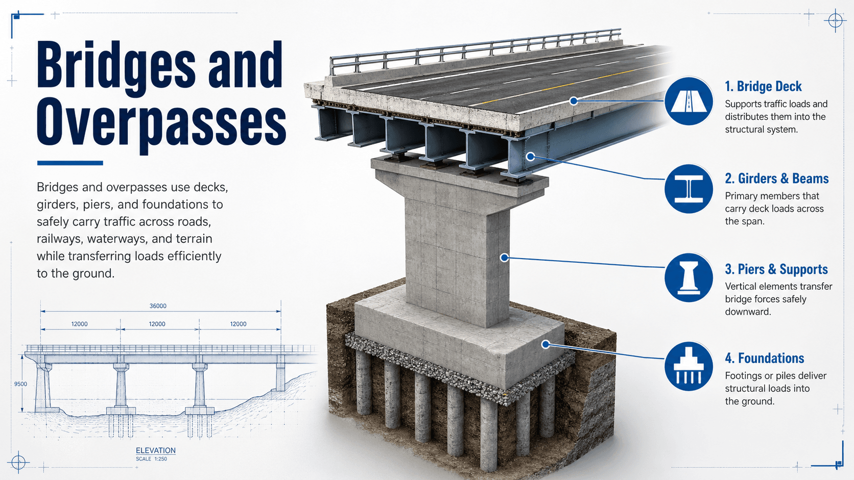
Notice that the deck is only one part of the system. The performance of the bridge depends on the complete load path, the support conditions, the foundation behavior, and the details that allow movement, drainage, and long-term inspection.
What Are Bridges and Overpasses?
A bridge is a structure that spans an obstacle while supporting people, vehicles, trains, utilities, pipelines, or other loads. The obstacle may be a river, ravine, roadway, railroad, floodplain, canal, or another structure. An overpass is a bridge used to carry one path over another, most often where a road, ramp, rail line, or pedestrian route crosses above a transportation corridor.
In everyday language, people often separate bridges from overpasses based on what they cross. In structural engineering, the distinction is less important than the load path, span arrangement, support layout, foundation conditions, movement details, and durability demands. A highway overpass may look simple from the road, but it still must resist gravity loads, braking forces, thermal movement, impact risk, drainage problems, fatigue, and long-term deterioration.
| Term | Meaning | Common example |
|---|---|---|
| Bridge | General structure that spans an obstacle. | River bridge, pedestrian bridge, rail bridge, utility bridge. |
| Overpass | Bridge that carries one route over another corridor. | Highway ramp over a freeway or road over a rail line. |
| Viaduct | Long elevated bridge, often with repeated spans. | Urban rail viaduct or elevated roadway over low ground. |
| Culvert | Hydraulic crossing beneath a roadway or embankment. | Box culvert carrying stormwater under a road. |
How Bridges Carry Loads
The most important structural idea behind bridges and overpasses is the load path. A vehicle, pedestrian, train, barrier impact, wind force, or thermal movement does not stop at the deck. That demand must move through a chain of connected elements until it is resisted by the foundation and supporting ground.
Superstructure
The superstructure is the part that directly spans between supports. It usually includes the deck, slab, girders, beams, trusses, arches, cables, diaphragms, cross frames, and wearing surface. This portion often controls span efficiency, stiffness, deflection, vibration, fatigue, and construction sequence.
Substructure
The substructure supports the spanning system and transfers reactions into the foundation. It includes piers, pier caps, columns, abutments, wingwalls, bearings, and sometimes retaining elements. Substructure layout is strongly affected by roadway clearance, waterway opening, skew, collision risk, and construction access.
Foundations and ground
Foundations transfer bridge loads into soil or rock. They may use spread footings, driven piles, drilled shafts, pile caps, or rock sockets. Foundation design is not only about vertical capacity; settlement, lateral load, scour, liquefaction, slope movement, and constructability can all control the final solution.
Common Types of Bridges and Overpasses
Bridge type selection depends on span length, site geometry, clearance, aesthetics, available materials, cost, construction staging, traffic control, foundation conditions, and expected maintenance. A short highway overpass and a long river crossing may both be bridges, but the efficient structural system can be completely different.
| Bridge type | How it works | Common use | Typical materials |
|---|---|---|---|
| Beam or slab bridge | Spans by bending between supports. | Short-span roads, pedestrian crossings, simple overpasses. | Reinforced concrete, prestressed concrete, steel. |
| Girder bridge | Main girders support the deck and transfer loads to bearings. | Highway overpasses, interchanges, medium spans. | Steel plate girders, prestressed concrete girders, box girders. |
| Truss bridge | Triangulated members carry loads mainly through axial tension and compression. | Medium spans, rail bridges, pedestrian bridges, historic crossings. | Steel, timber, aluminum in some lightweight applications. |
| Arch bridge | Curved form carries load primarily through compression. | Valleys, rivers, architectural crossings, masonry or concrete spans. | Concrete, steel, masonry, stone. |
| Cantilever bridge | Projecting arms carry loads back into supports and anchor spans. | Difficult crossings where falsework is limited. | Steel, reinforced concrete, prestressed concrete. |
| Cable-stayed bridge | Inclined cables transfer deck forces directly to towers. | Medium to long spans with strong visual identity. | Steel, concrete, stay cables. |
| Suspension bridge | Main cables carry deck loads through vertical hangers into towers and anchorages. | Very long spans over major waterways or valleys. | Steel cables, steel or concrete decks, massive anchorages. |
| Box girder bridge | Closed box section resists bending and torsion efficiently. | Curved ramps, elevated roadways, segmental bridges. | Prestressed concrete, steel, composite sections. |
The “best” bridge type is rarely chosen from appearance alone. Engineers first ask what span, clearance, foundation, construction staging, traffic control, durability, and inspection requirements control the project.
Main Bridge Components
Bridges and overpasses are easier to understand when their components are grouped by function. Some parts carry gravity load, some allow controlled movement, some protect users, and others manage water, soil, or long-term maintenance.
| Component | Primary function | Why engineers care |
|---|---|---|
| Deck | Supports traffic, pedestrians, rail, or utilities. | Controls ride quality, drainage, durability, cracking, and load distribution. |
| Girders, beams, or trusses | Span between supports and carry deck reactions. | Often control strength, deflection, fatigue, vibration, and constructability. |
| Bearings | Transfer reactions while allowing rotation or movement. | Prevent unintended restraint from thermal expansion, creep, shrinkage, and rotation. |
| Piers | Support intermediate spans. | Affected by vertical load, lateral load, collision, water flow, scour, and seismic demand. |
| Abutments | Support bridge ends and retain approach embankment. | Must handle vertical reactions, earth pressure, settlement, drainage, and approach movement. |
| Foundations | Transfer bridge loads into soil or rock. | Can control cost, risk, settlement, scour resistance, and construction method. |
| Expansion joints | Accommodate bridge movement at deck discontinuities. | Common maintenance point because leaking joints accelerate corrosion and deterioration. |
| Drainage and barriers | Remove water and protect users from edge or collision hazards. | Poor drainage can shorten service life even when the primary structure is strong. |
What Controls Bridge and Overpass Design?
Bridge design is controlled by more than member strength. The final system must fit the site, carry the required loads, allow movement, drain properly, resist deterioration, and remain accessible for inspection and maintenance. A design that looks efficient on paper can become expensive or risky if it is hard to build, hard to inspect, or vulnerable to water and corrosion.
| Design control | Why it matters | Engineering implication |
|---|---|---|
| Span length | Longer spans increase bending, deflection, vibration, and member depth. | May push the concept from slabs to girders, trusses, arches, or cable-supported systems. |
| Vertical and horizontal clearance | Roadways, railways, waterways, and utilities require protected openings. | Can control girder depth, pier placement, profile grade, and construction staging. |
| Skew and curvature | Angled or curved crossings create torsion and uneven load distribution. | May require diaphragms, box girders, refined analysis, and careful bearing layout. |
| Traffic loading | Vehicle loads, braking, impact, and future traffic demands affect member sizing. | Controls deck design, girder strength, fatigue checks, barriers, and load rating. |
| Hydraulics and scour | Water can remove soil around piers and abutments. | May control foundation depth, span length, waterway opening, and countermeasures. |
| Durability exposure | Deicing salts, moisture, freeze-thaw cycles, marine exposure, and drainage affect service life. | Drives cover, coatings, materials, joint details, deck protection, and inspection frequency. |
| Constructability | Traffic, site access, cranes, falsework, staging, and utilities shape what can be built safely. | Can make a theoretically efficient bridge type impractical for the actual project. |
Loads Engineers Consider
Bridge and overpass design must account for permanent loads, variable loads, environmental effects, accidental events, and construction-stage conditions. The controlling load case may differ for the deck, girder, bearing, pier, abutment, and foundation.
- Dead load: self-weight of the deck, girders, wearing surface, barriers, utilities, and permanent attachments.
- Live load: vehicles, trains, pedestrians, cyclists, maintenance equipment, or temporary traffic patterns.
- Dynamic and impact effects: added demand from moving loads, vibration, braking, and roughness.
- Wind and seismic loads: lateral and dynamic demands that can control tall piers, long spans, bearings, and restraints.
- Thermal movement: expansion and contraction from temperature changes that affect joints, bearings, and restraints.
- Hydraulic and scour effects: water pressure, debris, erosion, and loss of foundation support near waterways.
- Collision and accidental loads: vehicle, vessel, or rail impacts on piers, barriers, or superstructure elements.
- Construction loads: temporary equipment, staged placement, lifting, falsework, unbalanced cantilevers, and partially completed configurations.
A bridge can be strong under final design loads but vulnerable during construction, demolition, jacking, widening, or deck replacement. Temporary load paths deserve the same discipline as the finished structure.
Bridge and Overpass Materials
Material selection affects span capability, member depth, maintenance, corrosion protection, construction speed, cost, and long-term durability. Many modern bridges are composite systems, combining a concrete deck with steel or prestressed concrete girders so each material is used where it performs well.
- Reinforced concrete: common for decks, slabs, substructures, abutments, piers, and short-span systems.
- Prestressed concrete: widely used for girders because prestressing improves span efficiency and serviceability.
- Structural steel: efficient for girders, trusses, arches, and long-span systems where high strength-to-weight ratio matters.
- Weathering steel: useful in some environments when detailed to drain and dry properly.
- Timber and mass timber: used for pedestrian bridges, rural crossings, temporary structures, and selected specialty projects.
- Masonry and stone: common in historic arch bridges and legacy infrastructure.
- Composite and fiber-reinforced materials: used for strengthening, pedestrian decks, corrosion-prone environments, or lightweight applications.
For a deeper material path, review related Turn2Engineering guides on concrete design, steel design, timber design, and composite materials.
Bridge Type Selection Checklist
A practical bridge concept starts with constraints before member sizing. Use the following decision logic to understand why one project becomes a simple girder overpass while another needs a truss, arch, segmental box girder, or cable-supported system.
Start with the obstacle and required clearance. Establish the span arrangement. Check foundation feasibility. Select a structural system that can meet span, depth, skew, curvature, traffic staging, and durability requirements. Then confirm that the system can be inspected, drained, maintained, and built safely without creating temporary load path problems.
| Check or decision | What to look for | Why it matters |
|---|---|---|
| Define the obstacle | Road, rail, waterway, valley, utility corridor, or urban constraint. | The obstacle controls clearance, pier locations, hydraulic opening, and construction access. |
| Set span arrangement | Short single span, multi-span viaduct, long main span, or staged widening. | Span length strongly affects member depth, bridge type, cost, and foundation demand. |
| Check vertical profile | Available structure depth between roadway grade and required clearance. | Shallow profiles may require steel girders, prestressed elements, or alternative framing. |
| Review foundations | Soil strength, rock depth, scour, settlement, liquefaction, and lateral resistance. | A poor foundation condition can control the bridge layout more than the superstructure does. |
| Evaluate movement | Temperature range, creep, shrinkage, seismic displacement, and bearing behavior. | Movement details affect joints, bearings, restraints, abutments, and long-term maintenance. |
| Confirm maintainability | Access to bearings, joints, drainage, fracture-sensitive details, and underside inspection. | Hard-to-inspect structures often become expensive to own even if initial construction is efficient. |
Example: Choosing a Highway Overpass Concept
Consider a new two-lane roadway crossing over an existing highway. The site has limited traffic closure windows, a required vertical clearance over the highway, moderate skew, and enough room for abutments outside the clear zone. The obstacle is not a river, so scour does not control, but traffic staging and clearance do.
Concept decision
A common starting concept would be a steel girder or prestressed concrete girder overpass with a reinforced concrete deck. This system is efficient for short to medium spans, can be erected relatively quickly, and can keep piers away from active traffic lanes when the span arrangement allows it.
Engineering interpretation
The final choice would depend on available structure depth, girder shipping limits, crane access, skew effects, deck drainage, bearing layout, abutment design, and long-term maintenance. A shallow or highly skewed layout may push the design toward different girders, closer analysis of torsion, or changes in span arrangement.
Engineering Judgment and Field Reality
Real bridges are affected by water, traffic, vibration, corrosion, temperature, construction tolerances, settlement, fatigue, and maintenance access. A textbook diagram may show a clean load path, but field performance depends on details: whether water drains away, whether bearings can move, whether joints leak, whether reinforcement has enough cover, and whether inspectors can actually see critical elements.
Many bridge problems begin at details that seem secondary during concept design: leaking joints, clogged drains, restrained bearings, poor approach transitions, cracked deck overlays, and corrosion at girder ends.
Experienced engineers also think about ownership. A bridge that is slightly cheaper to build but difficult to inspect, difficult to repair, or vulnerable to routine water intrusion may be a poor long-term decision. The best bridge concept balances structural efficiency with durability, constructability, redundancy, access, and service life.
When This Breaks Down
Simplified bridge explanations break down when they treat the structure as a single member rather than an interacting system. A bridge is not just a deck on supports; it includes geometry, foundations, drainage, movement devices, barriers, approach conditions, and inspection requirements.
- Ignoring soil and water: foundations, settlement, scour, and erosion can control bridge safety even when the superstructure is adequate.
- Assuming supports are fixed or free without checking details: unintended restraint can create thermal force, bearing distress, cracking, or joint damage.
- Focusing only on strength: deflection, vibration, fatigue, crack control, drainage, and durability can govern service life.
- Forgetting construction stages: lifting, launching, falsework, staged demolition, and partial deck placement can create temporary conditions more critical than the final bridge.
- Overlooking maintenance access: a bridge that cannot be inspected or repaired efficiently may perform poorly over its life cycle.
Common Mistakes and Practical Checks
For students and early designers, the most common mistake is treating bridge type selection as a visual category instead of an engineering decision. The structural form must match the span, support conditions, loads, movement, durability exposure, and construction constraints.
- Confusing bridge type with bridge function: an overpass can be a girder bridge, slab bridge, truss bridge, box girder bridge, or other system.
- Missing the load path: every load must have a continuous route through members, bearings, substructure, foundations, and ground.
- Ignoring movement: temperature change, creep, shrinkage, and seismic displacement require compatible joints, bearings, and restraints.
- Underestimating drainage: water intrusion is one of the most common durability threats for decks, joints, bearings, girder ends, and abutments.
- Forgetting redundancy and inspection: critical details should be inspectable, understandable, and robust enough for long-term service.
Do not assume that a bridge is safe simply because its main span appears strong. Bearings, joints, drainage, foundations, scour protection, fatigue-sensitive details, and approach conditions can control real-world performance.
Relevant Manuals and Engineering References
Bridge and overpass design is typically governed by owner requirements, transportation agency criteria, structural design specifications, geotechnical data, hydraulic studies, inspection requirements, and local project conditions. These references help frame how engineers move from concept to design, evaluation, and maintenance.
- AASHTO LRFD Bridge Design Specifications: Widely used in U.S. highway bridge design for load and resistance factor design, load combinations, materials, limit states, and bridge-specific design provisions.
- FHWA bridge engineering resources: Provide federal guidance, research, and technical context for bridge design, preservation, hydraulics, geotechnical issues, inspection, and safety programs.
- National Bridge Inspection Standards: Establish inspection requirements and terminology for public highway bridges, helping owners evaluate condition, safety, and maintenance priorities.
- AISC and National Steel Bridge Alliance resources: Support steel bridge design, fabrication, detailing, constructability, fatigue awareness, and steel bridge best practices.
- Project-specific geotechnical and hydraulic reports: Translate site conditions into foundation recommendations, scour considerations, earth pressures, settlement estimates, and waterway constraints.
Frequently Asked Questions
A bridge is any structure that carries a roadway, railway, pedestrian path, utility, or other load over an obstacle. An overpass is a specific type of bridge that usually carries one transportation route over another road, railway, or corridor.
The main parts of a bridge include the deck, wearing surface, girders or trusses, bearings, piers, abutments, foundations, expansion joints, barriers, drainage elements, and approach slabs. Engineers often group these into the superstructure, substructure, and foundation system.
Highway overpasses commonly use reinforced concrete, prestressed concrete, steel girder, or concrete box girder systems because they are efficient for short to medium spans, can be built in stages, and fit well with roadway geometry and clearance requirements.
Bridge and overpass failures can result from deterioration, corrosion, fatigue, scour, foundation movement, overload, collision damage, poor drainage, construction defects, seismic movement, or loss of load path continuity. Most serious failures involve multiple issues rather than one isolated cause.
Summary and Next Steps
Bridges and overpasses are structural systems that carry loads over obstacles while maintaining safe clearance, serviceability, durability, and public use. An overpass is usually a bridge over another transportation corridor, but the engineering focus is the same: create a reliable load path from the deck to the supporting ground.
Good bridge engineering considers span arrangement, material selection, foundations, movement, drainage, traffic loading, scour, fatigue, inspection access, and construction staging. The strongest concept is not always the best concept if it is difficult to build, hard to inspect, or vulnerable to long-term deterioration.
Where to go next
Continue your structural engineering learning path with related Turn2Engineering resources.
-
Structural Loads
Learn the force types, load categories, and load combinations that control structural systems.
-
Load Path Analysis
Follow how gravity, lateral, and environmental loads move through a complete structure.
-
Foundation Design
Understand how bridge and building loads are transferred into soil or rock through foundations.