Key Takeaways
- Definition: Seismic testing measures how stress waves travel through the ground so engineers can estimate stiffness, layering, and dynamic soil properties.
- Use case: It is commonly used for shear-wave velocity profiling, site class determination, liquefaction screening, bedrock depth evaluation, and ground improvement verification.
- Main decision: The key judgment is choosing the right method and survey geometry for the depth, resolution, risk level, and site access constraints.
- Outcome: After reading, you should understand what seismic testing tells you, how results are interpreted, and where field judgment matters most.
Table of Contents
Introduction
In brief: Seismic testing uses wave travel through soil and rock to measure stiffness, layering, and shear-wave velocity for earthquake-related geotechnical design decisions.
Who it’s for: Students, FE/PE prep, and practicing geotechnical engineers.
In geotechnical work, seismic testing matters when you need more than a boring log and index properties. It helps convert the ground from a descriptive profile into a dynamic model that can support site response analysis, site classification, liquefaction screening, and performance-based design.
Seismic Testing infographic
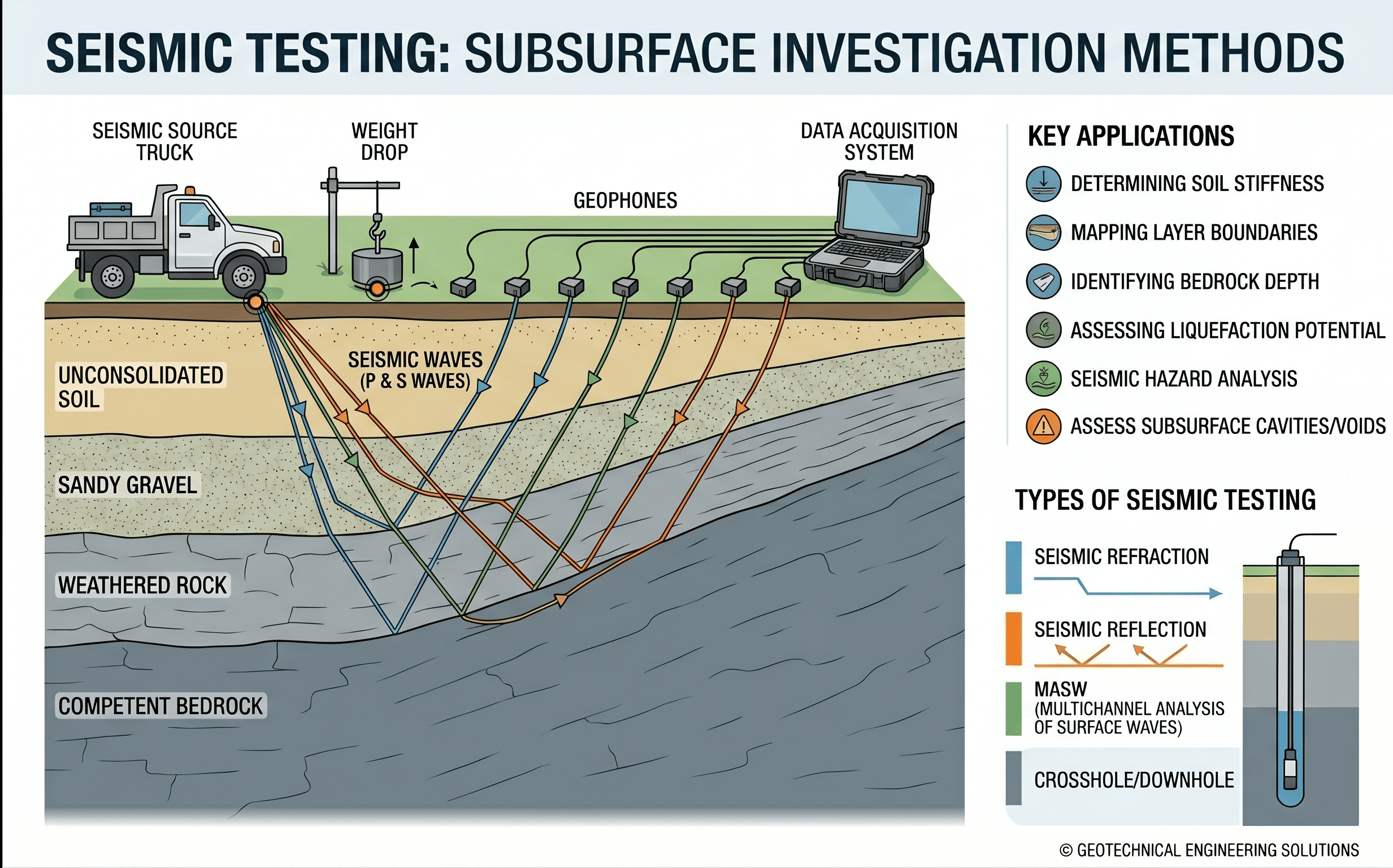
Start by noticing how the methods differ in geometry. Some tests read wave behavior from the surface, some use boreholes, and some combine seismic sensors with other exploration methods. That geometry controls depth reach, vertical resolution, field logistics, and confidence in the final interpretation.
What is seismic testing?
Seismic testing in geotechnical engineering is the measurement of wave propagation through soil or rock to estimate dynamic properties such as shear-wave velocity, compressional-wave velocity, stiffness, damping tendencies, and layer boundaries. In simple terms, it tells you how quickly the ground transmits a disturbance and how that transmission changes with depth.
The most important output on many projects is shear-wave velocity, usually written as \(V_S\). Because shear waves depend strongly on the soil skeleton, \(V_S\) is closely tied to small-strain stiffness. That makes seismic testing especially valuable when engineers need to understand how the ground will respond under earthquake shaking, machine vibration, traffic loading, or other dynamic effects.
Seismic testing is not a replacement for a full subsurface investigation. It works best as part of a broader characterization program that may also include Geotechnical Investigation, Geotechnical Data Analysis, borings, laboratory testing, and judgment grounded in local geology.
Why seismic testing matters in geotechnical engineering
Seismic testing matters because many geotechnical risks are controlled by stiffness and dynamic behavior, not just by static strength. A site can have adequate bearing capacity for a foundation and still perform poorly during earthquake shaking if the velocity structure amplifies motion, contains liquefiable layers, or transitions abruptly to stiff material.
This is where seismic testing adds information that common index tests cannot provide directly. A grain-size curve, plasticity index, or moisture content may help classify a soil, but those values do not by themselves define how stress waves travel through the profile or how the site will filter seismic energy.
- It supports site class determination and seismic design input selection.
- It improves subsurface models by identifying stiffness contrasts with depth.
- It provides a useful cross-check against SPT, CPT, and geologic interpretation.
- It helps verify whether ground improvement actually changed the ground response.
- It can sharpen decisions about liquefaction, settlement under cyclic loading, and seismic earth pressures.
The value of seismic testing is rarely the velocity number alone. It is the way that number changes with depth, matches geology, and fits the rest of the investigation program.
Core principles, variables, and units
Seismic testing is built around a few core physical ideas. A wave source or natural ambient vibration generates motion. Sensors record the arrival or dispersion behavior of the wave field. Engineers then reduce those measurements to velocities, depth-dependent profiles, and stiffness-related parameters that can be used in design.
Key variables and what they mean
The most common field variables are the travel time, path length, frequency content, and sensor spacing. After interpretation, the engineer usually works with wave velocities, layer thicknesses, and derived stiffness values. The key is not memorizing every symbol. It is understanding what each parameter says about how the ground deforms.
- \(V_S\) Shear-wave velocity, usually in m/s or ft/s; the most important dynamic stiffness indicator for many geotechnical applications.
- \(V_P\) Compressional-wave velocity, usually in m/s or ft/s; often used to help identify saturation, stiffness contrasts, and material boundaries.
- \(V_{S30}\) Average shear-wave velocity in the upper 30 m; commonly used for site classification in seismic design frameworks.
- \(t\) Travel time of the measured wave pulse or phase, usually in milliseconds or seconds.
- \(L\) Travel path length between source and receiver, in m or ft; geometry is critical because a wrong path assumption produces wrong velocity.
- \(G_{max}\) Maximum small-strain shear modulus; often estimated from density and shear-wave velocity.
- \(\rho\) Mass density, usually kg/m³ or slugs/ft³; needed to convert velocity to modulus.
Typical ranges and sanity checks
Soft clays and loose fills commonly show relatively low \(V_S\), while dense sands, cemented soils, weathered rock, and hard rock show much higher values. The exact ranges vary by geology, stress state, saturation, and structure, but the engineering habit is the same: check whether the reported profile makes sense compared with the boring logs, cone resistance, blow counts, and local geologic expectations.
A suspiciously smooth velocity profile through a highly variable fill site may be a red flag. So is a sharp velocity jump with no matching evidence in the borings. Good seismic data reduction is not just processing. It is reconciliation.
When the site is layered, focus on contrasts and transitions as much as the average velocity. Those interfaces often control amplification behavior, liquefaction sensitivity, and the reliability of simplified assumptions.
Main seismic testing methods and when to use them
There is no single best seismic test for every project. The correct choice depends on required depth, required resolution, budget, access, noise environment, drilling availability, and how critical the design decision is. The most useful framing question is this: do you need quick site-wide screening, high-resolution velocity data at depth, or a defensible dynamic profile for a high-consequence structure?
Surface-wave methods
Methods such as MASW and SASW infer subsurface \(V_S\) structure from surface-wave dispersion. They are efficient, non-intrusive, and often ideal for screening, corridor work, or sites where drilling is limited. They are especially practical when the project needs \(V_{S30}\) or a broader site-stiffness picture across a large footprint.
Refraction methods
Seismic refraction is commonly used to identify layer boundaries and approximate depth to stronger material or bedrock. It can be powerful for rippability and excavation planning, but it becomes less reliable when the subsurface includes hidden low-velocity layers beneath faster material.
Downhole and crosshole testing
These methods use boreholes and can provide stronger vertical control than many surface-only surveys. Downhole testing is often more accessible and economical than crosshole testing, while crosshole methods can provide excellent resolution for critical facilities when executed well. The tradeoff is cost, field control, casing quality, and borehole alignment demands.
Seismic CPT and hybrid approaches
Seismic CPT adds \(V_S\) data to the same sounding program that already produces tip resistance, sleeve friction, and pore pressure response. That combination can be extremely efficient because it links dynamic stiffness to a more familiar penetration profile. On many strong programs, hybrid methods produce the most defensible result because they reduce reliance on any one test type.
Decision logic or testing workflow
The testing workflow should follow the design question, not the other way around. Engineers do not run seismic surveys just because seismic methods are available. They run them because a project decision depends on dynamic stiffness, layering, or site classification.
Step 1: Define the reason for testing: site class, liquefaction, site response, bedrock depth, ground improvement verification, or dynamic foundation design.
Step 2: Set the needed depth and resolution: shallow screening, full upper 30 m characterization, or deeper basin/rock transition work.
Step 3: Choose the method that fits access, noise, drilling availability, and risk tolerance.
Step 4: Collect enough supporting geotechnical data to interpret the seismic profile credibly.
Step 5: Reduce the data, compare against geology and boring logs, and resolve mismatches before design values are issued.
Step 6: Translate the results into the actual design decision, such as \(V_{S30}\), \(G_{max}\), a layered response model, or a screening conclusion.
This workflow helps prevent a common problem: obtaining technically valid field data that still does not answer the actual project question. Seismic testing is only as useful as the decision chain it supports.
Equations and calculations
The core calculations behind seismic testing are simple in appearance but important in meaning. Field measurements typically begin with travel time and path length. Design interpretation often ends with wave velocity and stiffness.
Here, \(V\) is the wave velocity, \(L\) is the travel path length, and \(t\) is the measured travel time. For downhole, crosshole, and refraction work, the details of the actual wave path matter. A wrong geometry assumption gives a wrong velocity even if the recorded signal itself is clean.
This equation links shear-wave velocity to maximum small-strain shear modulus. It matters because the field often measures \(V_S\), but the analysis may require stiffness. Density must be in compatible units, and the resulting modulus reflects very small strain behavior, not the reduced stiffness that may govern under larger cyclic loading.
In this expression, \(d_i\) is the thickness of each layer within the top 30 m and \(V_{S,i}\) is the corresponding shear-wave velocity for that layer. It is a harmonic-style average, which means thin slow layers can influence the result significantly. That is one reason why layering detail matters.
Worked example
Example: estimating \(V_{S30}\) from a layered profile
Suppose a site investigation produces the following interpreted shear-wave velocity profile for the upper 30 m:
- 0 to 6 m: \(V_S = 160\) m/s
- 6 to 14 m: \(V_S = 220\) m/s
- 14 to 24 m: \(V_S = 320\) m/s
- 24 to 30 m: \(V_S = 500\) m/s
Compute \(V_{S30}\):
The denominator is approximately \(0.0375 + 0.0364 + 0.0313 + 0.0120 = 0.1172\). Therefore:
The important lesson is not just the arithmetic. Notice how the slower upper layers strongly affect the average. Even though the deeper material is much stiffer, the near-surface zone still controls much of the result. That is why shallow poor material can meaningfully affect site class and surface amplification behavior.
How seismic testing is used in real projects
Real projects use seismic testing for different reasons, and those reasons shape how aggressive the program needs to be. A warehouse site may only need a dependable basis for site classification and a check on soft near-surface layers. A bridge, dam, tall building, or critical facility may need much deeper and more carefully constrained dynamic characterization.
| Project need | Typical seismic objective | Why it matters |
|---|---|---|
| Building seismic design | Determine \(V_{S30}\) and stiffness layering | Supports site classification and the motion model used by the design team. |
| Liquefaction screening | Estimate dynamic stiffness and compare with other in-situ indicators | Adds a useful cross-check where cyclic behavior and strain compatibility matter. |
| Ground improvement verification | Compare pre- and post-treatment \(V_S\) profiles | Helps confirm whether densification or stabilization changed stiffness meaningfully. |
| Excavation and rock transition work | Identify stronger layers or bedrock surface | Improves planning, excavation risk estimates, and constructability. |
| Transportation and embankment work | Map variability and weak zones along alignment | Supports targeting of mitigation and a more efficient investigation plan. |
The strongest programs connect seismic results to adjacent topics such as Liquefaction, Seismic Design, Soil Mechanics, and Ground Improvement.
Engineering judgment and field reality
This is where experienced engineers separate themselves from checkbox workflows. Seismic testing can look objective because it produces clean plots and velocity numbers, but the field reality is that data quality depends heavily on source consistency, receiver coupling, noise environment, borehole condition, line orientation, inversion assumptions, and the geologic model you bring into interpretation.
A velocity inversion can appear polished and still be misleading. Urban noise can contaminate records. Borehole deviation can distort crosshole geometry. Lateral variability can make a single line look more representative than it really is. Even when the field data are strong, the reduction method can impose smoothness that hides thin but important layers.
If the seismic profile conflicts with the borings, do not force either dataset to “win” too early. Reconcile the geology, check the survey setup, and decide whether the conflict is real variability or a testing artifact.
Another field judgment issue is depth of interest. Teams sometimes run shallow screening methods and then try to stretch the results into deeper conclusions. That is a design risk, not a reporting style issue. The test has to match the depth that actually matters.
When this breaks down
Seismic testing becomes less reliable when the method assumptions do not match the site or the design question. Refraction methods struggle when a slower layer is trapped beneath a faster layer. Surface-wave methods can lose credibility when the site has strong lateral heterogeneity or when the inversion is poorly constrained. Downhole and crosshole work can degrade quickly if casing installation, borehole alignment, or source triggering are inconsistent.
Interpretation also breaks down when engineers treat dynamic stiffness as a substitute for every other geotechnical property. A high \(V_S\) does not automatically mean good drainage behavior, low settlement, or no collapsible structure. Likewise, a site classification output should not be mistaken for a complete seismic hazard model.
The method also breaks down from a workflow standpoint when there is no clear plan for how the result will be used. Seismic testing should end in a decision: a design parameter set, a site class, a ground model, a verification conclusion, or a need for more investigation.
Common pitfalls and engineering checks
- Using a method with inadequate depth reach for the design problem.
- Assuming the inversion output is uniquely correct without checking geologic reasonableness.
- Confusing small-strain stiffness with large-strain design stiffness.
- Ignoring noise, coupling quality, or borehole construction issues.
- Reporting velocity profiles without clearly stating the method, assumptions, and quality-control basis.
- Failing to compare seismic results against boring logs, CPT/SPT trends, and groundwater information.
One of the costliest mistakes is treating seismic testing as a stand-alone substitute for subsurface characterization. It is a powerful layer of evidence, but it still has to be tied back to geology, sampling, and engineering context.
| Check item | What to review | Why it matters |
|---|---|---|
| Survey geometry | Source-receiver spacing, line length, and borehole layout | Controls resolution, depth reach, and whether the measured path assumption is defensible. |
| Signal quality | Noise level, repeatability, phase clarity, and trigger consistency | Weak signal quality can make a polished output unreliable. |
| Correlation | Compare with borings, CPT/SPT, geology, and groundwater | Improves confidence and helps resolve false layer interpretations. |
| Use in design | Confirm the result feeds a real decision | Prevents collecting dynamic data that never gets translated into design action. |
Visualizing seismic testing in practice
A useful mental model is to think of seismic testing as reading the stiffness architecture of the ground. The surface methods give you a broad picture of how the upper profile behaves, while borehole-based methods sharpen the vertical detail. When engineers overlay that stiffness architecture onto borings and geologic interpretation, the subsurface model becomes much more actionable.
The goal is not just to identify layers, but to understand which layers control motion, deformation, and uncertainty.
Relevant standards and design references
Seismic testing programs should be tied to recognized standards, agency guidance, and project-specific criteria. The exact governing references vary by jurisdiction and project type, but these are the kinds of sources engineers commonly rely on:
- ASTM D7400: Covers downhole seismic testing and helps standardize how shear-wave velocity is measured in boreholes.
- ASTM D4428/D4428M: Addresses crosshole seismic testing procedures for subsurface materials.
- ASTM D5777: Covers the use of the seismic cone penetration test for measuring shear-wave velocity during CPT sounding.
- Agency seismic design provisions and site-class frameworks: Used when the velocity data support code-based structural and geotechnical seismic design decisions.
- Project geotechnical investigation specifications: These often control required depth, QC expectations, reporting format, and whether seismic data must be correlated with borings and lab results.
Frequently asked questions
Seismic testing focuses on wave propagation, shear-wave velocity, stiffness, damping tendencies, and dynamic layering, while broader geotechnical soil testing also includes classification, strength, consolidation, and permeability work. In practice, seismic methods are usually one part of the larger geotechnical testing program rather than a replacement for it.
Shear-wave velocity is important because it is strongly tied to the stiffness of the soil skeleton at small strain. Engineers use it to estimate dynamic modulus, compare layers, classify sites, and support seismic design decisions in a way that many index tests cannot do directly.
It becomes less reliable when the survey geometry is poor, noise contaminates the records, lateral variability is strong, borehole conditions are weak, or the inversion assumptions do not represent the actual site. The best protection is to interpret seismic results alongside borings, CPT/SPT data, geology, and project judgment.
It shows up in building and bridge design, site class evaluation, liquefaction screening, ground improvement verification, transportation corridors, dams, retaining systems, and major earthwork projects. Any project where dynamic soil behavior matters can benefit from a properly scoped seismic testing program.
No. Seismic testing is best used as a complementary method that improves the stiffness and layering picture, but borings, sampling, lab tests, and geologic interpretation are still needed for classification, strength, compressibility, groundwater understanding, and engineering judgment.
Summary and next steps
Seismic testing helps engineers understand how the ground behaves dynamically by measuring wave travel through soil and rock. Its most common value is the production of defensible shear-wave velocity profiles, which can then support site classification, stiffness estimation, liquefaction screening, and site response work.
The strongest seismic testing programs are built around a clear design question, an appropriate method, and disciplined reconciliation with the rest of the geotechnical investigation. Good engineering does not stop at a velocity number. It turns that number into a decision that is technically defensible and project-relevant.
If you are learning this topic, the next step is to connect seismic testing to the broader geotechnical system around it: soil behavior, seismic design intent, and how dynamic parameters are used in real projects. That is where the method becomes useful rather than merely interesting.
Where to go next
Continue your learning path with these related geotechnical resources.
-
Study Soil Mechanics
Build the stiffness, stress, and behavior foundation that makes seismic testing results easier to interpret.
-
Read the Liquefaction guide
See how dynamic stiffness and earthquake loading tie directly into one of the most important seismic geotechnical hazards.
-
Continue to Seismic Design
Move from site characterization into how seismic parameters inform real design choices and demand models.