Key Takeaways
- Core idea: Steel reinforcement is embedded in concrete to resist tension, control cracking, and add ductility where plain concrete is weak.
- Engineering use: Engineers use rebar, welded wire reinforcement, ties, stirrups, and prestressing steel to make beams, slabs, columns, walls, and footings act as reliable reinforced concrete members.
- What controls it: Bar size, grade, spacing, concrete cover, development length, lap splices, exposure, member geometry, and constructability all affect reinforcement performance.
- Practical check: Rebar only works when it is placed, supported, developed, protected, and inspected as intended; small field placement errors can change structural behavior.
Table of Contents
Introduction
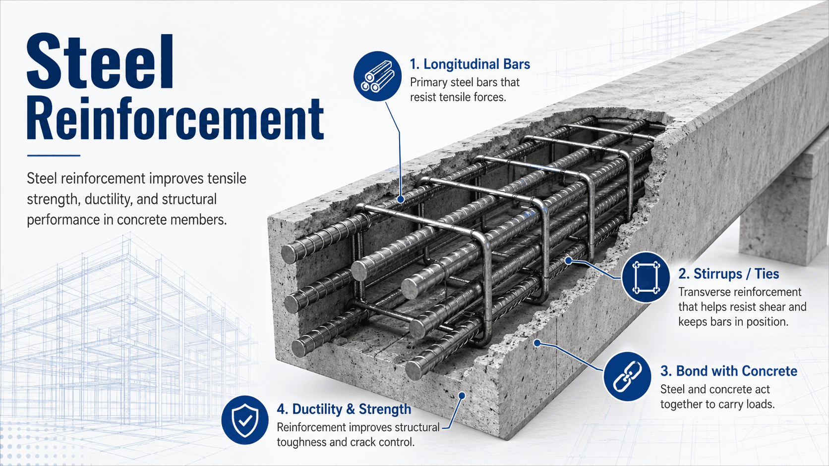
Steel reinforcement is steel bar, wire, mesh, or strand embedded in concrete to resist tension, control cracking, and improve ductility. Concrete carries compression well, but many structural members develop tensile stresses from bending, shear, shrinkage, temperature movement, settlement, or seismic loading. Reinforcement gives the cracked concrete section a dependable load path after plain concrete alone would no longer be enough.
How Steel Reinforcement Works in Concrete
Notice that reinforcement is not just “metal inside concrete.” Its location, embedment, spacing, and protection determine whether the member can develop the strength and crack-control behavior assumed in design.
What Is Steel Reinforcement?
Steel reinforcement is the reinforcing steel placed inside concrete or masonry so the finished member can resist actions that brittle, unreinforced concrete handles poorly. The most familiar form is deformed reinforcing bar, or rebar, but the category also includes welded wire reinforcement, stirrups, ties, spirals, dowels, mechanical splices, and high-strength prestressing steel.
In structural engineering, reinforcement is part of the load-resisting system. It is selected and detailed to carry tension, confine concrete, resist shear, control shrinkage and temperature cracks, transfer force across joints, and give members warning before failure. A bar schedule is therefore not just a material list; it is a map of how force is expected to move through the concrete.
Reinforced concrete is a composite system. Concrete provides compressive strength, stiffness, fire resistance, and shape; steel reinforcement provides tensile strength, ductility, crack control, and force transfer after cracking.
How Steel and Concrete Work Together
A reinforced concrete member works because concrete and steel share load through bond. Before cracking, concrete and steel deform together. After cracking, the concrete still carries compression and helps protect the steel, while the reinforcement carries tension across cracked regions and prevents a sudden brittle separation.
Tension, compression, and bending
In a simply supported concrete beam loaded downward, the top of the beam tends to be in compression while the bottom tends to be in tension. Plain concrete may crack at the tension face, so longitudinal steel is placed near the tension zone. At supports, continuous beams and slabs may reverse this pattern, requiring top reinforcement for negative moment.
Bond, ribs, and development
Deformed bars have ribs that improve mechanical bond with concrete. That bond allows stress to transfer from concrete into steel and back again. The bar must also be embedded far enough, or properly hooked, coupled, or anchored, so it can develop its intended force before pulling out or splitting the surrounding concrete.
Crack control and ductility
Reinforcement does not make concrete crack-free. Instead, good reinforcement distributes cracking, keeps crack widths smaller, and allows the member to carry load after cracking. Ductile behavior is especially important because yielding steel usually gives more warning than crushing concrete or brittle bond failure.
Where Steel Reinforcement Is Used in Structures
Steel reinforcement appears anywhere concrete needs tensile resistance, confinement, shear capacity, continuity, or crack control. The exact placement changes by member type because each member receives and transfers force differently.
- Beams: longitudinal bars resist flexural tension, while stirrups help resist shear and confine the beam core.
- Slabs: reinforcing bars or welded wire reinforcement resist bending, distribute concentrated loads, and control shrinkage and temperature cracking.
- Columns: vertical bars carry axial and bending demand, while ties or spirals restrain buckling and confine concrete.
- Walls: vertical and horizontal reinforcement resist bending, shear, temperature movement, shrinkage, and lateral loads.
- Footings: bottom reinforcement helps resist bending from soil pressure, while dowels connect columns or walls into the foundation system.
- Bridges and parking structures: reinforcement must also be detailed for durability, fatigue, corrosion exposure, and constructability.
A rebar detail should be reviewed by asking: where is the tension zone, how does force get into the bar, how does force leave the bar, and what protects that bar for the life of the structure?
Key Factors That Control Reinforcement Performance
Steel reinforcement performance depends on more than steel strength. A high-strength bar placed in the wrong location, with insufficient cover, poor anchorage, inadequate spacing, or heavy congestion may not perform as intended. The practical design problem is to make the reinforcement strong, developable, durable, and buildable at the same time.
| Factor | Why it matters | Engineering implication |
|---|---|---|
| Bar size | Larger bars provide more steel area but require more embedment and create more congestion. | Bar selection must balance strength, crack control, spacing, lap length, and constructability. |
| Steel grade | Higher yield strength can reduce required area but may affect development and ductility considerations. | Grade selection should match the design assumptions, code limits, and detailing requirements. |
| Concrete cover | Cover protects reinforcement from corrosion, fire exposure, and surface damage. | Too little cover reduces durability; too much cover may reduce effective depth and crack control efficiency. |
| Spacing and congestion | Concrete must flow around reinforcement and consolidate without honeycombing. | Crowded bars can reduce bond quality, create voids, and make inspection difficult. |
| Development length | Bars need enough embedded length to transfer stress into the concrete. | Short bars, poorly located cutoffs, or inadequate hooks can cause pullout or splitting failures. |
| Exposure environment | Moisture, chlorides, carbonation, and cracking can accelerate reinforcement corrosion. | Durability may control cover, concrete quality, coatings, stainless reinforcement, or maintenance planning. |
Types, Sizes, and Grades of Steel Reinforcement
Most reinforced concrete uses deformed carbon-steel bars because they are economical, widely available, and bond well with concrete. Other reinforcement types are chosen when speed, corrosion resistance, crack distribution, congestion reduction, or prestressing behavior matters.
Common reinforcement types
| Type | Typical use | Practical note |
|---|---|---|
| Deformed rebar | Beams, slabs, columns, walls, footings, and foundations | The default reinforcement for most cast-in-place concrete members. |
| Stirrups and ties | Shear reinforcement, confinement, and bar restraint | Small placement errors can significantly affect shear and confinement behavior. |
| Welded wire reinforcement | Slabs, pavements, panels, and repetitive layouts | Useful for distribution steel, but it must stay at the correct depth during placement. |
| Epoxy-coated or galvanized rebar | Bridge decks, parking structures, marine-adjacent work, and corrosive exposure | Protective systems only work if coatings are handled and repaired correctly. |
| Stainless steel reinforcement | High-durability or aggressive exposure structures | Higher material cost may be justified where corrosion risk dominates life-cycle cost. |
| Prestressing steel | Prestressed beams, slabs, girders, and precast elements | Uses high-strength steel stressed to improve service behavior and span efficiency. |
Common U.S. rebar sizes
U.S. bar numbers are related to nominal diameter in eighths of an inch. For example, a #4 bar is approximately 4/8 in, or 1/2 in, in nominal diameter. Actual design tables should be checked for exact area and weight.
| Bar size | Nominal diameter | Nominal area | Common use |
|---|---|---|---|
| #3 | 0.375 in | 0.11 in² | Stirrups, ties, light slabs, small members |
| #4 | 0.500 in | 0.20 in² | Slabs, walls, residential footings, light beams |
| #5 | 0.625 in | 0.31 in² | Beams, footings, walls, slabs with higher demand |
| #6 | 0.750 in | 0.44 in² | Beams, columns, foundations, heavier walls |
| #7 to #11 | 0.875 to 1.410 in | 0.60 to 1.56 in² | Larger beams, columns, mats, bridge and heavy civil work |
Rebar grades
Rebar grade generally refers to yield strength. Grade 60 reinforcement, for example, has a nominal yield strength of 60 ksi. Higher grades may reduce bar area, but they can also change detailing requirements, development length, ductility expectations, and availability.
Cover, Spacing, Development Length, and Lap Splices
Many reinforcement problems are not caused by the wrong steel strength; they are caused by the steel not being able to act as designed. Cover, spacing, anchorage, and splicing control how reinforcement interacts with the surrounding concrete.
Concrete cover
Concrete cover is the distance from the concrete surface to the outermost reinforcement. It protects steel from corrosion and fire exposure, helps provide bond, and keeps reinforcement in the correct structural location. Required cover depends on exposure, member type, bar size, construction tolerance, and project requirements.
Bar spacing
Bar spacing must allow concrete to pass between bars and consolidate around the reinforcement. Tight spacing can create voids, honeycombing, poor bond, and inspection problems. Very wide spacing may reduce crack control or leave tension zones under-reinforced.
Development length and lap splices
Development length is the embedded length needed for a bar to develop its design force. A lap splice overlaps bars so force transfers from one bar to the next through the concrete. Both are affected by bar size, steel grade, concrete strength, coating, cover, spacing, confinement, and whether the bar is in tension or compression.
- \(A_s\) Total provided steel area in the reinforcement layer, commonly in square inches or square millimeters.
- \(n\) Number of bars in the layer or group being checked.
- \(A_b\) Area of one reinforcing bar from the applicable bar size table.
This relationship is only a starting point. The provided steel area must still be checked for location, spacing, development, cover, constructability, crack control, and the member’s actual load path.
Steel Reinforcement Design Review Checklist
A useful reinforcement review follows the force path before it focuses on bar counts. The goal is to confirm that the reinforcement is needed, placed in the right zone, developed properly, protected from exposure, and buildable in the field.
Trace the load path → identify the tension, shear, confinement, or crack-control demand → select the bar size and grade → verify cover and spacing → check development and splices → review congestion and placement tolerances → confirm inspection points before concrete placement.
| Check or decision | What to look for | Why it matters |
|---|---|---|
| Tension zone | Bars placed near the correct face for positive or negative moment. | Steel must be where tensile stress develops, not merely present somewhere in the member. |
| Shear and confinement | Correct stirrup, tie, hook, and spacing details near supports, joints, and column ends. | Shear and confinement failures can be brittle and may not provide much visible warning. |
| Lap and development | Sufficient splice length, correct splice locations, and adequate anchorage at cutoffs and supports. | Bars that cannot develop force cannot deliver the strength assumed by the design. |
| Cover and exposure | Specified clear cover, chairs, spacers, and corrosion protection for the exposure condition. | Durability often controls the long-term performance of reinforced concrete. |
| Congestion | Room for aggregate, vibration, embeds, sleeves, post-installed anchors, and inspection access. | A theoretically strong detail can fail in practice if concrete cannot be placed and consolidated. |
Example: Reading Reinforcement in a Concrete Beam
Consider a reinforced concrete beam carrying gravity load between two supports. The bottom face near midspan is usually the primary tension zone, so bottom longitudinal bars are provided for positive moment. Near continuous supports, the top face may become the tension zone, so top bars may be required for negative moment.
What the rebar is doing
The bottom bars resist flexural tension after the concrete cracks. Stirrups wrap around the longitudinal bars and help resist shear near the supports. Top bars over supports provide continuity and resist negative bending. Each bar also needs enough development or anchorage so it can actually reach its intended stress.
Interpretation in the field
If bottom bars are lifted too high during placement, the beam loses effective depth and flexural capacity. If stirrups are spaced too widely near supports, shear behavior may be compromised. If top bars are omitted at a continuous support, the actual beam may not match the assumed structural model.
Engineering Judgment and Field Reality
Reinforcement drawings show design intent, but concrete placement introduces real tolerances. Bars move when workers walk on mats, when concrete is discharged, when vibrators are inserted, and when supports are missing or poorly spaced. Good detailing anticipates this by leaving room for placement, avoiding unnecessary congestion, and making critical bars inspectable before the pour.
The most important reinforcement is not always the largest bar. Small ties, stirrups, dowels, corner bars, temperature steel, and properly located top bars often control crack behavior, confinement, continuity, and whether the structure behaves as a complete system.
Experienced engineers also look beyond the individual member. A wall dowel must align with the wall above. A slab bar must clear sleeves and embeds. Column ties must be buildable around longitudinal bars. Foundation reinforcement must work with anchor bolts, shear keys, post-installed anchors, and concrete placement sequencing.
When This Breaks Down
Steel reinforcement concepts break down when the assumed bond, location, durability, or load path is not achieved. The presence of steel does not automatically make concrete safe; the reinforcement has to be detailed and placed so it can develop force at the right time and in the right location.
- Poor bond: voids, honeycombing, severe contamination, inadequate consolidation, or bad bar placement can reduce force transfer.
- Insufficient cover: corrosion risk increases when reinforcement is too close to the surface, especially in wet, chloride, or exterior exposure.
- Inadequate development: bars that are too short, cut off too early, or poorly spliced may not reach their intended stress.
- Unexpected load path changes: openings, penetrations, repairs, removed supports, or construction changes can move tension zones away from where bars were placed.
- Excessive congestion: tightly packed reinforcement can prevent concrete from flowing and consolidating around the steel.
Common Mistakes and Practical Checks
Many reinforcement mistakes are simple to describe but serious in consequence. They usually involve placing the correct material in the wrong location, assuming a generic spacing works for every condition, or ignoring how the concrete will actually be placed around the steel.
- Using rebar as a generic recipe: “#4 at 12 inches” means little without member depth, load, support conditions, exposure, and development details.
- Letting reinforcement sag or float: bars must be held in the intended position with chairs, spacers, ties, and inspection before concrete placement.
- Ignoring lap splice locations: splices should not be placed casually in high-demand zones unless the design specifically allows it.
- Overlooking penetrations and embeds: sleeves, drains, anchor bolts, and blockouts can interrupt bars or force field modifications.
- Confusing wire mesh with primary rebar: welded wire reinforcement may control cracking in some slabs, but it is not automatically a substitute for designed flexural reinforcement.
- Assuming rust is always acceptable or always unacceptable: light surface rust is different from section loss, delamination, or corrosion products that affect bond and durability.
The most dangerous assumption is that reinforcement only needs to be present. In structural concrete, reinforcement must be the right type, size, grade, location, spacing, cover, splice, and anchorage for the member’s actual demand.
Useful Standards and Design References
Steel reinforcement design and detailing are project-specific, but several widely used references help engineers specify material properties, design reinforced concrete members, and communicate reinforcement placement clearly.
- ACI 318: Commonly used for structural concrete design provisions, including strength design, reinforcement detailing, cover, development, splices, shear, flexure, columns, walls, slabs, and foundations.
- ASTM A615/A615M: Covers deformed and plain carbon-steel bars for concrete reinforcement and is commonly associated with standard reinforcing bar grades.
- ASTM A706/A706M: Covers low-alloy steel deformed and plain bars where weldability and controlled mechanical properties are important, often relevant for seismic detailing.
- CRSI Manual of Standard Practice: Provides reinforcement detailing, bar supports, placing practices, bending details, and construction communication guidance.
- Project structural drawings and specifications: Control the actual bar sizes, spacing, cover, lap locations, coatings, inspection requirements, and acceptance criteria for a specific project.
Frequently Asked Questions
Steel reinforcement is steel bar, wire, mesh, or strand embedded in concrete so the member can resist tension, control cracking, and behave more ductilely after concrete cracks. The most common form is deformed rebar, which bonds with the surrounding concrete through its ribbed surface.
Steel is used because concrete is strong in compression but weak in tension. In beams, slabs, walls, footings, and columns, loads often create tensile stresses that plain concrete cannot carry well. Steel reinforcement provides tensile capacity, ductility, crack control, and anchorage for load transfer.
Rebar size and spacing are controlled by structural demand, member depth, concrete strength, steel grade, cover, crack control, development length, bar congestion, exposure conditions, and constructability. The correct layout should come from the structural design drawings and governing design criteria.
Rebar does not prevent all concrete cracking. Reinforced concrete is often expected to crack in controlled ways under tension, shrinkage, temperature movement, or loading. Proper reinforcement limits crack width, holds cracked concrete together, and allows the member to keep carrying load safely.
Summary and Next Steps
Steel reinforcement is the steel placed inside concrete to provide tensile strength, crack control, ductility, confinement, shear resistance, and force transfer. It is one of the core reasons reinforced concrete can be used for beams, slabs, walls, columns, footings, bridges, and other structural systems.
The most important practical idea is that reinforcement must be detailed as a system. Bar size and grade matter, but so do cover, spacing, development length, lap splices, corrosion protection, concrete consolidation, and field placement tolerance.
Where to go next
Continue your learning path with related Turn2Engineering resources.
-
Reinforced Concrete Structures
Learn how concrete and steel reinforcement work together in complete structural members and systems.
-
Concrete Design
Review the broader design concepts behind reinforced concrete beams, slabs, columns, walls, and foundations.
-
Rebar Calculator
Estimate bar counts, spacing, weight, and layout quantities for common reinforcement planning tasks.