Key Takeaways
- Core idea: A capacitor stores energy in an electric field between conductive plates separated by an insulating dielectric.
- Engineering use: Capacitors are used for filtering, smoothing, timing, coupling, voltage support, reactive power compensation, and power factor correction.
- What controls it: Capacitance depends on plate area, dielectric permittivity, plate spacing, voltage rating, frequency, temperature, and real component losses.
- Practical check: A capacitor bank is not “free power”; it must be checked for load profile, voltage rise, switching transients, harmonics, resonance, protection, and discharge safety.
Table of Contents
Introduction
Capacitors are passive electrical components that store energy in an electric field between conductive surfaces separated by a dielectric. In power systems, capacitors are more than small circuit parts: they are used in capacitor banks to supply reactive power, support voltage, reduce source current, and improve power factor when applied with the right system checks.
How a Capacitor Stores Energy
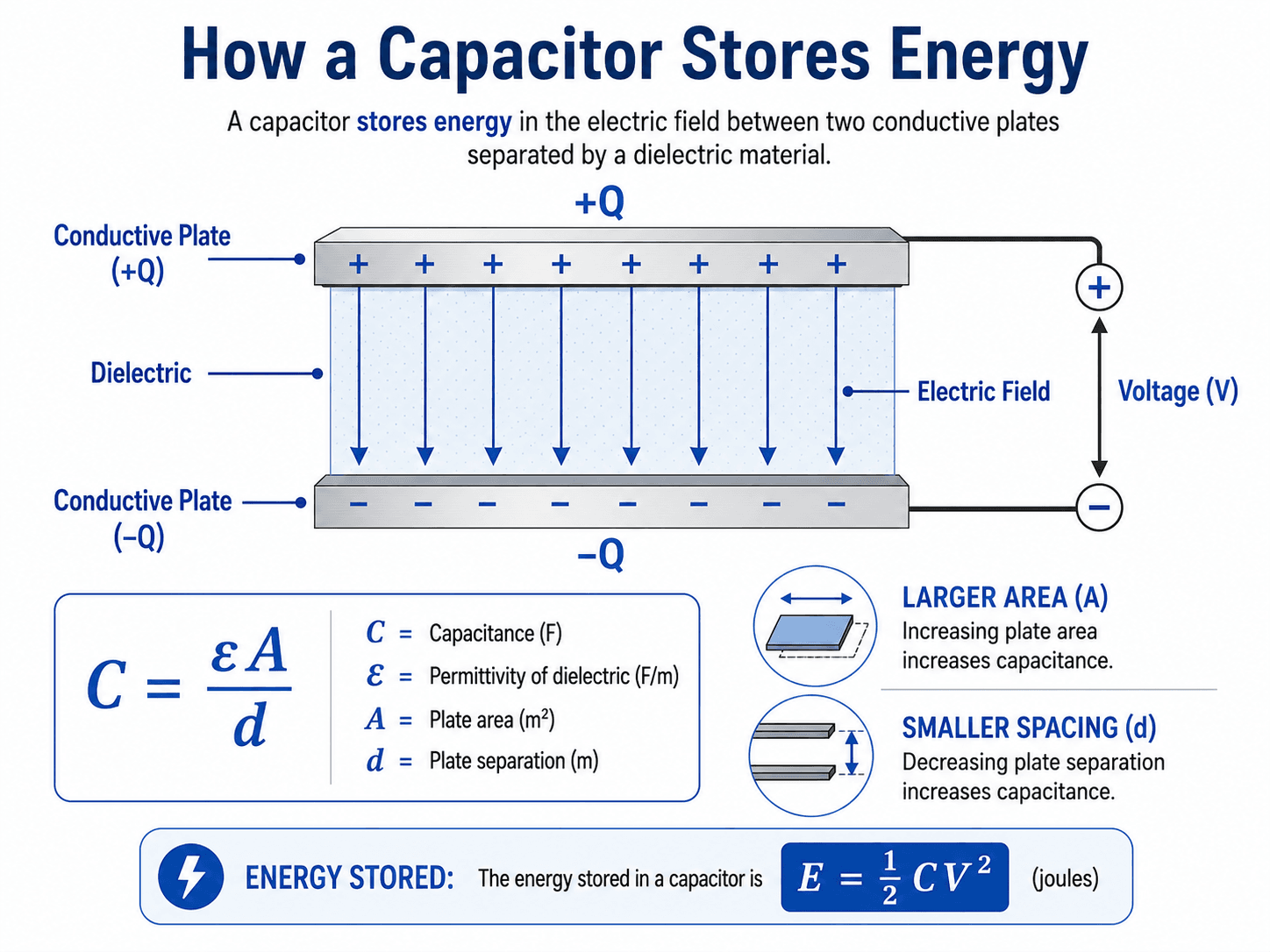
The most important idea is that charge does not pass through the dielectric in normal operation. Instead, separated charge creates an electric field, and that field stores energy.
What Is a Capacitor?
A capacitor is a two-terminal electrical component that stores energy by separating positive and negative charge. In its simplest form, it has two conductive plates separated by a dielectric material such as air, plastic film, ceramic, oxide, paper, oil, or another insulating medium.
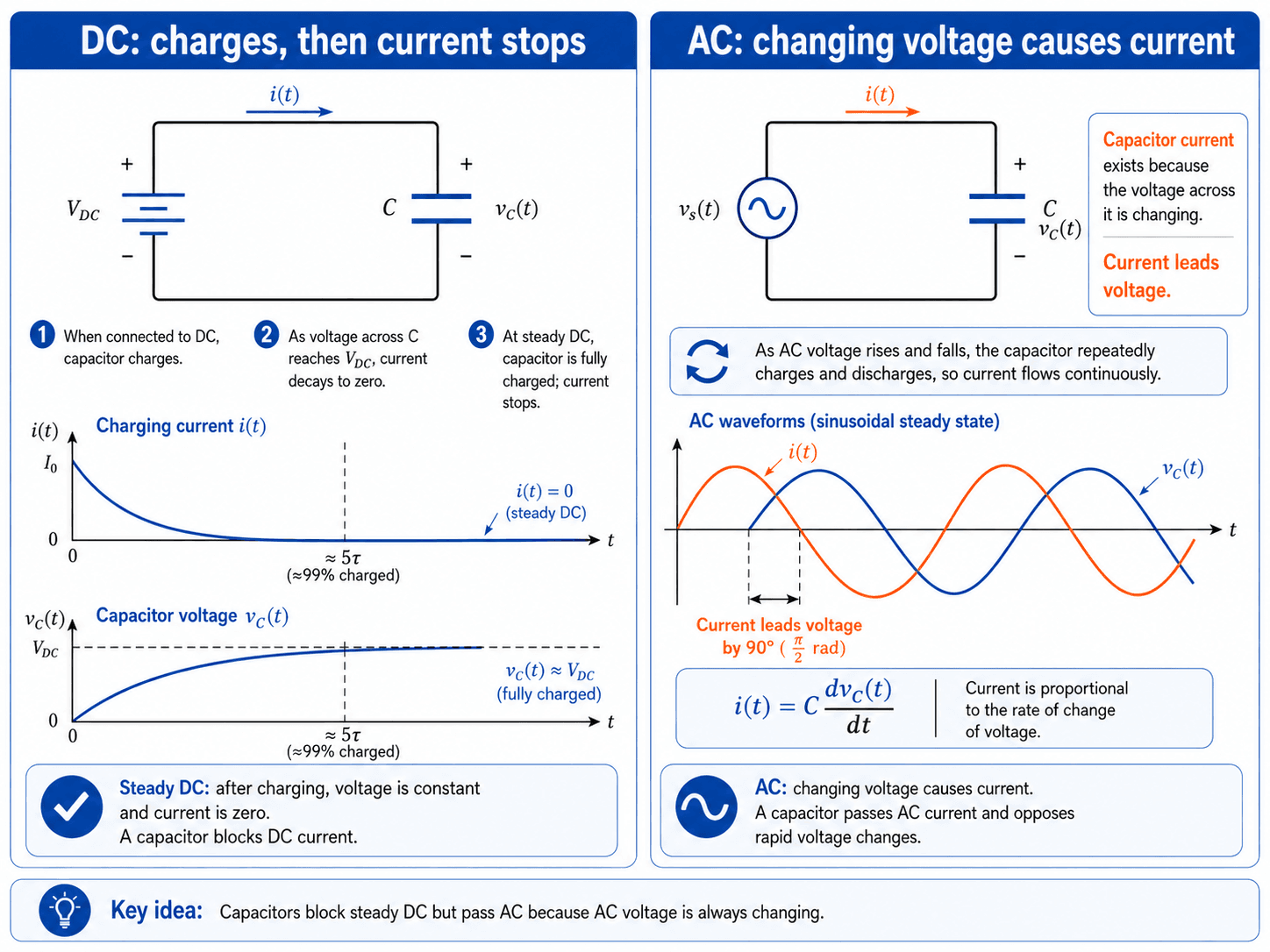
The practical value of a capacitor comes from how it responds to changing voltage. In a DC circuit, it charges toward the applied voltage and then ideally stops carrying steady current. In an AC circuit, the voltage continuously changes, so the capacitor repeatedly charges and discharges. That behavior makes capacitors useful in filters, power supplies, motor circuits, electronics, substations, and power factor correction systems.
A capacitor stores energy; in AC power systems, it primarily affects reactive power rather than supplying continuous real power to the load.
How Capacitors Work in DC and AC Circuits
When a voltage is applied across a capacitor, one plate accumulates positive charge and the other accumulates negative charge. The dielectric prevents direct conduction between the plates, but the electric field between them stores energy. If the voltage changes, charge must move into or out of the plates, which creates current in the external circuit.
The most common capacitor confusion is the difference between temporary charging current under DC and continuous alternating current under AC.
DC charging behavior
In a DC circuit, an initially uncharged capacitor behaves like a temporary current path while it charges. As capacitor voltage rises toward the source voltage, charging current decreases. Once the capacitor is fully charged and the voltage is steady, an ideal capacitor behaves like an open circuit for DC.
AC behavior and phase relationship
In a sinusoidal AC circuit, capacitor current leads capacitor voltage because current is greatest when the voltage is changing fastest. This is the opposite of an inductor, where current lags voltage. The leading current behavior is why capacitors can offset lagging reactive demand from inductive loads.
Real capacitors are not ideal
Practical capacitors have equivalent series resistance, equivalent series inductance, leakage current, dielectric losses, voltage limits, temperature limits, and life limits. These non-ideal properties are why a capacitor that works in a small signal circuit may not be appropriate for a power supply, motor circuit, or medium-voltage capacitor bank.
Key Capacitor Equations and Units
Capacitor equations connect charge, voltage, current, energy, geometry, and frequency behavior. The same physical ideas apply from small electronics to power systems, but the useful rating may change from farads at the component level to kVAR or MVAR at the capacitor-bank level.
The charge stored on a capacitor is proportional to capacitance and voltage. Here, \(Q\) is charge in coulombs, \(C\) is capacitance in farads, and \(V\) is voltage in volts.
Stored energy increases with capacitance, but it increases with the square of voltage. This is why voltage rating and discharge safety become critical as capacitor size and system voltage increase.
Capacitor current depends on the rate of change of voltage. A steady voltage produces no ideal capacitor current, while a rapidly changing voltage can create large charging or switching currents.
Capacitive reactance decreases as frequency increases. At low frequency, a capacitor tends to look more like an open circuit; at higher frequency, it offers lower reactance. This frequency dependence is central to filtering, harmonic interaction, and power-system resonance concerns.
| Capacitance unit | Symbol | Equivalent in farads | Where it commonly appears |
|---|---|---|---|
| Farad | F | \(1\ F\) | Base SI unit; very large for many small electronic components. |
| Millifarad | mF | \(10^{-3}\ F\) | Bulk storage, supercapacitor-related discussions, and some power electronics contexts. |
| Microfarad | \(\mu F\) | \(10^{-6}\ F\) | Electrolytic capacitors, motor capacitors, power supplies, and filtering. |
| Nanofarad | nF | \(10^{-9}\ F\) | Signal filters, timing circuits, and general electronics. |
| Picofarad | pF | \(10^{-12}\ F\) | RF circuits, small ceramic capacitors, stray capacitance, and high-frequency effects. |
- C Capacitance, measured in farads. Practical component values often use microfarads, nanofarads, or picofarads.
- V Voltage across the capacitor. Voltage strongly affects stored energy because energy is proportional to \(V^2\).
- f Frequency in hertz. Frequency controls capacitive reactance and affects AC behavior, filtering, harmonics, and resonance.
- Q Charge in coulombs for circuit theory, or reactive power in VAR/kVAR/MVAR when discussing AC power systems. Context matters.
Capacitors in Series and Parallel
Capacitors can be connected in series or parallel to change equivalent capacitance, voltage sharing, energy storage, and circuit behavior. These relationships are especially important in filters, timing circuits, DC bus design, and high-voltage capacitor assemblies.
Capacitors in parallel
Parallel capacitors add directly because each capacitor has the same voltage across it and contributes additional charge storage.
Capacitors in series
Series capacitors reduce equivalent capacitance because the same charge must be stored through each capacitor. Series arrangements may be used for voltage sharing, but they require careful design because real capacitors do not always divide voltage equally.
In high-voltage capacitor assemblies, voltage balancing, tolerances, leakage differences, and protection are just as important as the ideal series-capacitance equation.
Types, Ratings, and Selection Checks
Capacitor type matters because dielectric material, construction, voltage rating, equivalent series resistance, leakage, tolerance, temperature behavior, and expected life vary widely. A capacitor should be selected for the circuit function, not just the capacitance value printed on the case.
| Capacitor type | Common use | Engineering implication |
|---|---|---|
| Ceramic capacitor | Decoupling, bypassing, high-frequency filtering, small signal circuits. | Compact and fast, but capacitance may vary with voltage, temperature, and dielectric class. |
| Electrolytic capacitor | Power supply smoothing, bulk energy storage, DC bus filtering. | High capacitance in a small package, but polarity, ripple current, temperature, and lifetime must be checked. |
| Film capacitor | AC applications, power electronics, motor run circuits, pulse duty, filtering. | Often stable and lower-loss than electrolytics, with strong use cases where AC stress and reliability matter. |
| Supercapacitor | Short-duration energy buffering, ride-through, memory backup, regenerative capture. | Very high capacitance, but lower voltage per cell and different leakage, balancing, and energy-density tradeoffs than batteries. |
| Power capacitor / capacitor bank | Power factor correction, voltage support, reactive power compensation, harmonic filter banks. | Usually rated in kVAR or MVAR at a specific voltage and frequency, with protection, switching, discharge, and harmonic checks required. |
Capacitor rating checks
A capacitor datasheet or nameplate should be read as a set of constraints. Capacitance alone does not tell you whether the component can survive the applied voltage, ripple current, ambient temperature, duty cycle, and expected service life.
| Rating or parameter | What it means | Why it matters |
|---|---|---|
| Capacitance | Nominal charge-storage capability. | Affects charge, stored energy, reactance, filtering, timing, and reactive power output. |
| Voltage rating | Maximum voltage stress the capacitor is designed to withstand. | Underrating can lead to dielectric failure, overheating, rupture, or unsafe operation. |
| Tolerance | Allowed variation from the nominal capacitance value. | Changes filter frequency, timing behavior, resonance, and expected reactive output. |
| Ripple current | RMS AC current the capacitor can carry without excessive heating. | Critical for power supplies, inverters, DC bus capacitors, and harmonic-rich applications. |
| ESR | Equivalent series resistance inside the real capacitor. | Creates heat and losses; lower ESR is often needed for high ripple current and fast switching. |
| Temperature rating | Permitted operating temperature range. | High temperature accelerates aging, especially for electrolytic and power capacitors. |
| Life rating | Expected operating life under stated temperature and electrical conditions. | Important for reliability planning, maintenance, and replacement intervals. |
Two capacitors with the same farad value can behave very differently under ripple current, AC voltage, switching duty, temperature, harmonic distortion, or long service life requirements.
Capacitors vs Batteries vs Inductors
Capacitors are often compared with batteries and inductors because all three relate to energy storage, but they store and exchange energy in very different ways. Understanding the difference helps prevent common mistakes in circuit design and power systems interpretation.
| Comparison point | Capacitor | Battery | Inductor |
|---|---|---|---|
| Energy storage mechanism | Electric field between charged conductors. | Chemical energy converted to electrical energy. | Magnetic field created by current flow. |
| Primary circuit behavior | Opposes sudden voltage changes. | Provides sustained DC energy supply. | Opposes sudden current changes. |
| Typical time scale | Fast charge and discharge, usually short-duration energy exchange. | Longer-duration energy delivery. | Fast to moderate magnetic energy exchange depending on circuit inductance. |
| AC phase behavior | Ideal current leads voltage. | Not normally modeled as an AC reactive component. | Ideal current lags voltage. |
| Power systems relevance | Reactive power support, voltage support, power factor correction, harmonic filtering. | Backup power, energy storage systems, DC systems, ride-through. | Motors, transformers, reactors, fault current behavior, filters, and magnetic devices. |
Capacitors in Power Systems
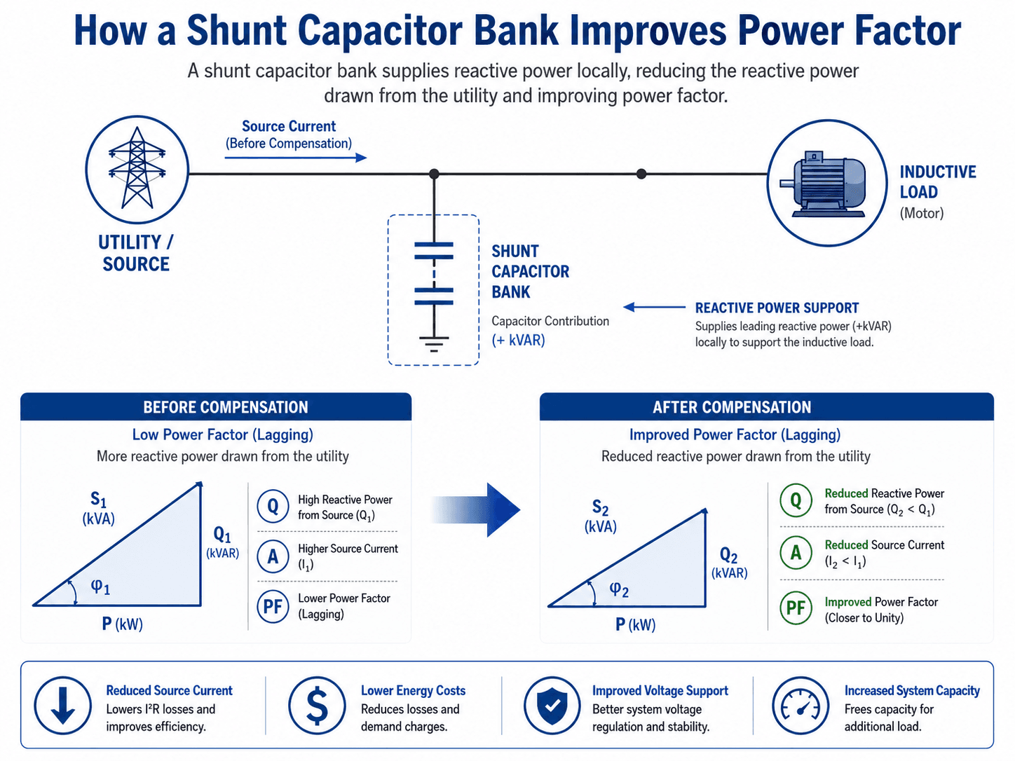
In power systems, capacitors are commonly applied as shunt capacitor banks connected near loads, on distribution feeders, in substations, or at industrial facilities. Their main job is to supply leading reactive power locally so the upstream source does not have to deliver as much lagging reactive power to inductive loads.
Leading and lagging reactive power
Inductive loads such as motors and transformers typically draw lagging reactive power, which means current lags voltage. Capacitors supply leading reactive power, where current leads voltage. When applied correctly, the leading contribution from the capacitor offsets part of the lagging reactive demand from the load.
Why capacitor banks are rated in kVAR
Small capacitors are usually discussed in farads. Power system capacitor banks are usually discussed in kVAR or MVAR because the practical question is how much reactive power the bank supplies at the system voltage and frequency. A bank’s reactive output depends on its capacitance, applied voltage, and frequency.
How capacitors improve power factor
Many power system loads, especially motors and transformers, draw lagging reactive power. A shunt capacitor bank supplies leading reactive power near the load. This reduces the reactive component that must flow through upstream conductors, transformers, and switchgear. The result can be lower source current, lower \(I^2R\) losses, reduced kVA demand, better voltage support, and improved use of system capacity.
Where capacitors are commonly installed
Capacitors may be installed at individual equipment, motor control centers, service entrances, distribution feeders, or substations. The best location depends on load variability, voltage profile, utility requirements, switching strategy, harmonics, maintenance access, and whether compensation should support one load, one facility, or a wider feeder area.
What Controls Capacitor Performance?
A capacitor’s useful performance is controlled by more than capacitance. Engineers also check voltage rating, frequency, ripple current, dielectric behavior, temperature, losses, switching duty, harmonics, and the system condition where the capacitor will operate.
| Control or condition | Why it matters | Engineering implication |
|---|---|---|
| Voltage rating | Stored energy and dielectric stress increase with applied voltage. | Underrated capacitors can fail prematurely, rupture, overheat, or create unsafe service conditions. |
| Capacitance tolerance | The actual capacitance may differ from the nominal value. | Filter response, timing behavior, resonance frequency, and reactive power output can shift from the expected value. |
| Frequency | Capacitive reactance decreases as frequency increases. | Frequency affects filtering, charging current, harmonic current, and the reactive output of power capacitors. |
| ESR and ripple current | Real capacitors dissipate heat when AC or ripple current flows through internal resistance. | Excess ripple current can overheat capacitors and shorten service life, especially in power electronics and DC bus applications. |
| Harmonic distortion | Capacitors can interact with system inductance at harmonic frequencies. | Power capacitor banks may require harmonic studies, detuning reactors, filtering, or different switching strategies. |
| Load profile | Reactive demand changes as motors, drives, and facility loads cycle on and off. | Fixed capacitors can overcorrect during light load; stepped or automatic banks may be needed for variable loads. |
Capacitor Bank Design Review Checklist
Capacitor banks should be reviewed as part of the power system, not as isolated devices. A mathematically correct kVAR value can still cause field problems if voltage rise, harmonics, switching, protection, and load variation are ignored.
Start with the measured load profile and existing power factor, estimate the needed compensation, check voltage and harmonic conditions, select fixed or switched steps, then review protection, switching duty, discharge provisions, and maintenance access before installation.
| Design or review check | What to look for | Why it matters |
|---|---|---|
| Existing and target power factor | Measured kW, kVAR, kVA, and load power factor during representative operating periods. | Correction should be based on real operating conditions, not a single nameplate value. |
| Load variation | Motors, HVAC, pumps, compressors, and process loads that cycle or operate seasonally. | Variable loads often need automatic capacitor steps to avoid overcorrection during light load. |
| Voltage rise | Expected bus voltage before and after capacitor switching. | Capacitors can raise voltage; too much compensation may create overvoltage or regulator coordination problems. |
| Harmonics and resonance | VFDs, rectifiers, UPS equipment, nonlinear loads, and existing harmonic measurements. | Capacitors can amplify harmonic currents if the bank resonates with system inductance. |
| Switching transients | Expected inrush, restrike risk, step switching frequency, and controller behavior. | Capacitor switching can stress breakers, contactors, fuses, arresters, and nearby equipment. |
| Protection and discharge | Fusing, unbalance protection, grounding, discharge resistors, lockout practice, and warning labels. | Failed units must be isolated safely, and stored energy must be reduced before maintenance. |
| Maintenance access | Inspection points for bulging cases, leaking fluid, hot connections, blown fuses, corrosion, and abnormal noise. | Capacitor banks need practical access for inspection and troubleshooting, especially in harsh electrical rooms or substations. |
Worked Example: Stored Energy in a Capacitor
Suppose a \(1000\ \mu F\) capacitor is charged to \(50\ V\). First convert capacitance to farads:
Then calculate stored energy:
What the result means
The capacitor stores 1.25 joules at 50 volts. That may sound small, but stored energy grows with the square of voltage. A much larger capacitor bank at power-system voltage can store hazardous energy and must be treated with proper discharge and verification practices.
How this connects to power systems
A capacitor bank stores energy in its electric field, but unlike a battery, it is not intended for long-duration energy supply. In AC power systems, it repeatedly exchanges energy with the system each cycle while supplying leading reactive power.
Engineering Judgment and Field Reality
Ideal capacitor theory assumes perfect plates, perfect dielectric insulation, zero resistance, zero inductance, and clean sinusoidal voltage. Field conditions are messier. Capacitors are exposed to temperature, harmonic currents, switching operations, utility voltage variation, enclosure heat, aging dielectric systems, loose connections, and protection coordination issues.
A capacitor bank that improves power factor at one load condition can overcorrect at another. Always review the load profile, not just the peak kW and a single target power factor.
Experienced engineers also avoid assuming that capacitor banks automatically reduce energy use. They can reduce losses and demand penalties in some systems, but they do not reduce the real power required by the load. A motor still needs roughly the same mechanical power output; the capacitor changes how much reactive power the source must supply.
When This Breaks Down
Simplified capacitor explanations are useful for learning, but they can become misleading when the system is high voltage, high frequency, nonlinear, thermally stressed, or heavily distorted by harmonics.
- High-frequency behavior: Equivalent series inductance can make a capacitor stop behaving like a simple ideal capacitor at high frequency.
- Harmonic-rich systems: Capacitor banks can create resonance with transformer and feeder inductance, increasing harmonic current instead of improving power quality.
- Light-load operation: Fixed capacitor banks may overcorrect power factor and raise voltage when inductive load is low.
- Thermal stress: Ripple current, high ambient temperature, poor ventilation, and internal losses can shorten capacitor life.
- Aging and dielectric degradation: Capacitance, leakage, and failure risk can change over time, especially under voltage, temperature, and switching stress.
Common Capacitor Mistakes and Practical Checks
Capacitors are simple in principle, but mistakes often happen when learners confuse charge, energy, current, and reactive power or when designers treat capacitor banks as a one-step fix for all power-quality issues.
| Common mistake | Why it is wrong | Better engineering check |
|---|---|---|
| Assuming a capacitor stores current | A capacitor stores energy in an electric field created by separated charge. | Use \(Q = CV\) for charge and \(E = \frac{1}{2}CV^2\) for stored energy. |
| Assuming capacitors permanently pass DC | An ideal capacitor only has transient current under DC while voltage is changing. | Check whether the circuit is in the charging transient or steady-state condition. |
| Selecting only by capacitance value | Voltage rating, ESR, ripple current, temperature, dielectric type, and lifetime may control suitability. | Compare the full rating set against the actual circuit stress. |
| Oversizing power factor correction | Too much capacitance can cause leading power factor, voltage rise, and utility or equipment issues. | Review the load profile and consider stepped or automatic correction. |
| Ignoring harmonics | Capacitor banks can resonate with the system and amplify harmonic currents. | Review nonlinear loads and perform harmonic or resonance checks where needed. |
Do not treat a capacitor bank as a universal power-quality fix. It can improve displacement power factor, but it may not solve voltage flicker, harmonic distortion, poor grounding, equipment overload, or nonlinear load problems.
Engineering References and Design Guidance
Capacitor theory can be learned from circuit equations, but power-system capacitor banks require application, protection, rating, and safety context. For shunt power capacitor applications, IEEE guidance is a strong reference point for engineers reviewing medium-voltage and high-voltage capacitor bank projects.
- IEEE 1036: IEEE guide for the application of shunt power capacitors covers application guidance for shunt power capacitors, including practical considerations such as ratings, protection, and reliable utilization.
- Project-specific criteria: Utility requirements, owner standards, equipment manufacturer instructions, harmonic studies, and site operating conditions may control the final capacitor bank design.
- Engineering use: Engineers use references like this to move from a simple kVAR target to a complete application review covering voltage, switching, protection, discharge, and system interaction.
Frequently Asked Questions
A capacitor stores electrical energy in an electric field between two conductive surfaces separated by a dielectric. In circuits, that stored energy can be released when voltage changes, which makes capacitors useful for filtering, timing, smoothing, coupling, reactive power support, and power factor correction.
A capacitor initially charges when connected to DC, but once its voltage reaches the applied DC voltage, the current ideally drops to zero. With AC, the voltage is always changing, so the capacitor repeatedly charges and discharges, creating continuous alternating current in the circuit.
Capacitance is measured in farads, abbreviated F. Practical component values are often given in microfarads, nanofarads, or picofarads, while power system capacitor banks are usually discussed by their reactive power rating in kVAR or MVAR at a specified voltage and frequency.
Capacitors improve power factor by supplying leading reactive power near inductive loads such as motors and transformers. This reduces the reactive power drawn from the utility source, lowers apparent power demand, can reduce current, and may improve voltage support when applied correctly.
Yes. Capacitors can retain stored energy after equipment is de-energized, especially if discharge paths fail or are not provided. Larger power capacitors and capacitor banks require proper discharge provisions, verification, and maintenance practices before they are handled or serviced.
Summary and Next Steps
Capacitors store energy in an electric field and respond strongly to changing voltage. That simple principle explains why capacitors appear in filters, power supplies, timing circuits, motor applications, substations, and power factor correction systems.
For power systems, the most important practical ideas are reactive power, kVAR output, load profile, voltage support, harmonics, switching transients, protection, and discharge safety. A good capacitor application is not just about adding capacitance; it is about applying the right compensation at the right location under the right operating conditions.
Where to go next
Continue your learning path with related Turn2Engineering resources.
-
Power Factor Calculator
Estimate power factor, apparent power, reactive power, and correction kVAR using AC power triangle relationships.
-
Voltage Regulation
Learn how capacitor banks, transformers, feeder impedance, and reactive power support affect voltage profiles.
-
Impedance Calculator
Explore how capacitance, inductance, resistance, reactance, phase angle, and AC impedance interact in circuit analysis.