Key Takeaways
- Core idea: Circuit simulation uses mathematical models and software solvers to predict voltage, current, timing, frequency response, and component stress before a circuit is physically built.
- Engineering use: Engineers use SPICE-style simulation to test design choices, compare component values, find schematic mistakes early, and reduce prototype cycles.
- What controls it: Results depend on the schematic, component models, source definitions, ground reference, loads, simulation type, solver settings, and assumptions.
- Practical check: A clean waveform is not proof the circuit will work in hardware; tolerance, parasitics, PCB layout, temperature, and measurement loading still matter.
Table of Contents
Introduction
Circuit simulation is the process of using software to model an electronic circuit and predict how it will behave before it is built. A simulator solves the circuit equations from a schematic or netlist, then returns outputs such as node voltage, branch current, waveform shape, gain, cutoff frequency, power dissipation, and device operating conditions.
How Circuit Simulation Moves From Schematic to Decision
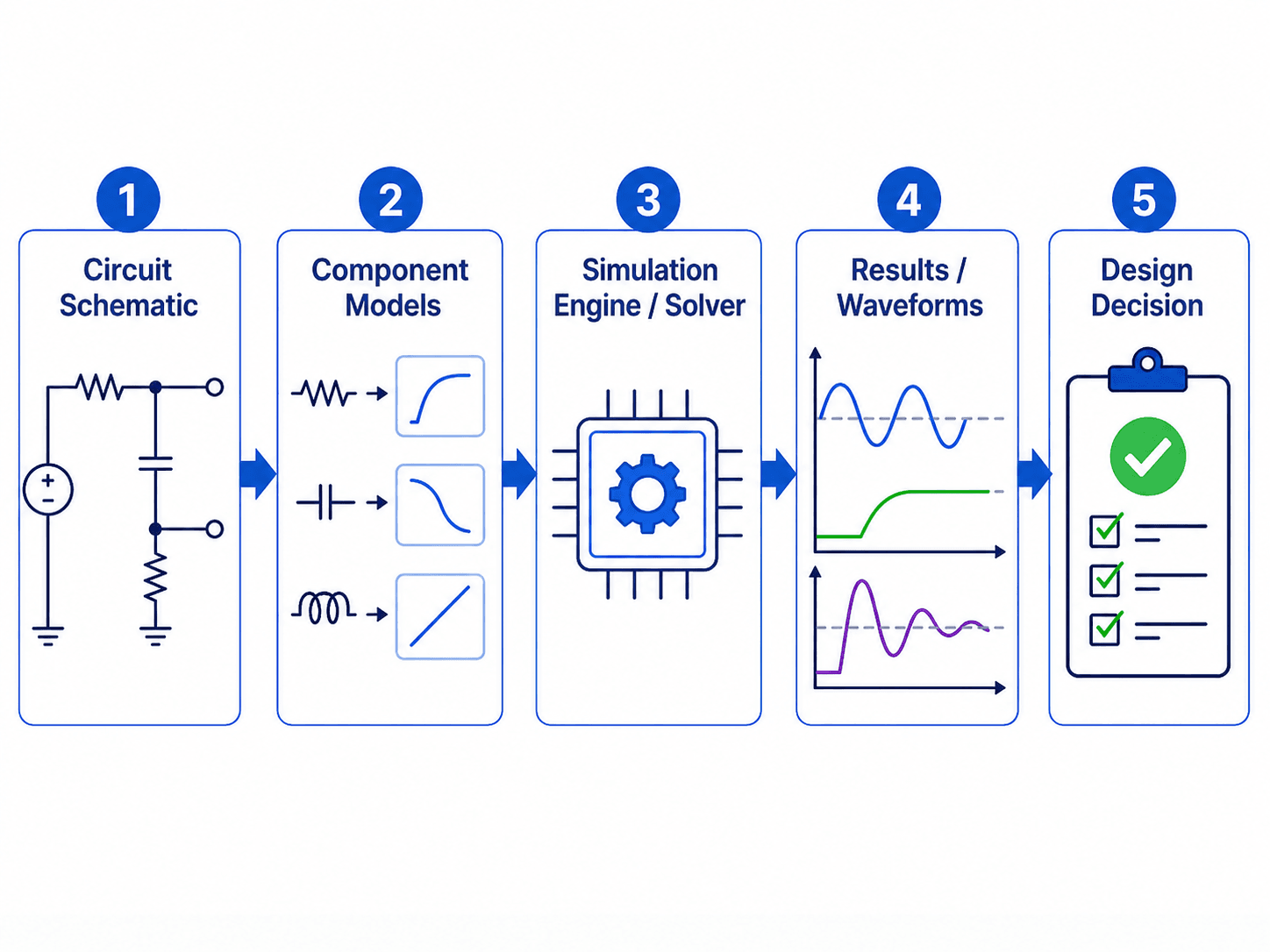
The most important idea is that simulation is not just drawing a circuit. The quality of the result depends on the model behind each component and the engineering question the simulation is set up to answer.
What is Circuit Simulation?
Circuit simulation is a modeling method used in electronics engineering to estimate how a circuit will respond to electrical inputs. The simulator represents resistors, capacitors, inductors, diodes, transistors, operational amplifiers, voltage sources, current sources, and other devices with mathematical models. It then solves the circuit for the requested operating condition.
In practical design work, simulation helps answer questions such as: What is the output voltage? Will the op-amp saturate? What is the cutoff frequency? How long does the capacitor take to charge? Does the transistor bias point make sense? Is a component dissipating too much power? Those answers guide a design before wiring a breadboard or ordering a PCB.
Circuit simulation can include analog simulation, digital simulation, mixed-signal simulation, power electronics simulation, and schematic-level checks before PCB layout. Most introductory circuit simulation focuses on analog/SPICE behavior, but real electronic products often combine analog front ends, digital logic, embedded control, power conversion, and board-level layout effects.
How Circuit Simulation Works
A circuit simulator starts with circuit connectivity. In a graphical tool, that connectivity comes from a schematic. In a text-based workflow, it may come from a netlist. Either way, the simulator needs to know which nodes are connected, what components are connected between those nodes, which node is ground, and what electrical models apply to each part.
Schematic or Netlist
The schematic defines the topology of the circuit. A netlist is the text-based version of that same idea: it lists components, node names, values, sources, and model references. A voltage divider, RC filter, op-amp amplifier, transistor bias circuit, and switching regulator all become a network of nodes and branches.
Component Models
Simple resistors and capacitors may use ideal values, but active devices usually need more detailed models. Diodes, MOSFETs, BJTs, op-amps, regulators, and integrated circuits can behave very differently depending on the model selected. A generic op-amp model may be fine for learning gain behavior but poor for checking output swing, input common-mode limits, slew rate, stability, or supply current.
Solver and Output
The solver calculates the requested response. It may solve a static operating point, sweep a source value, linearize the circuit around a bias point, or step through time. The output is usually a plot or table showing voltages, currents, gain, phase, device operating points, power values, or convergence messages.
Beginner Workflow: How to Simulate a Circuit Correctly
A good simulation starts with a clear question. Do not begin by asking the software to “simulate everything.” Decide whether you are checking bias, gain, cutoff frequency, startup behavior, power stress, tolerance sensitivity, or a troubleshooting symptom.
Define the design question first, choose the simulation type second, then review the model before interpreting the plot. A polished waveform can still be useless if it answers the wrong engineering question.
| Step | What to do | Why it matters |
|---|---|---|
| 1. Define the question | State whether you need bias, timing, frequency response, stress, or tolerance behavior. | The simulation type should match the design decision. |
| 2. Draw the simplest complete schematic | Include the source, ground, circuit elements, load, and output node. | A missing reference or load can make the result unrealistic. |
| 3. Assign component values and models | Use real part models where device limits matter. | Ideal parts hide saturation, bandwidth, leakage, ESR, and thermal limits. |
| 4. Choose the analysis | Use operating point, DC sweep, AC sweep, transient, noise, or tolerance analysis as needed. | Each simulation type answers a different question. |
| 5. Add source and load realism | Model source resistance, load impedance, rise time, probes, and relevant parasitics. | Real circuits are rarely driven by ideal sources or measured by ideal instruments. |
| 6. Compare against a hand estimate | Check divider voltage, RC time constant, gain, impedance, or power with a simple calculation. | A rough estimate catches many schematic, unit, and setup mistakes. |
| 7. Review voltage, current, and power | Do not inspect only the output voltage plot. | A circuit can produce the desired signal while overstressing a component. |
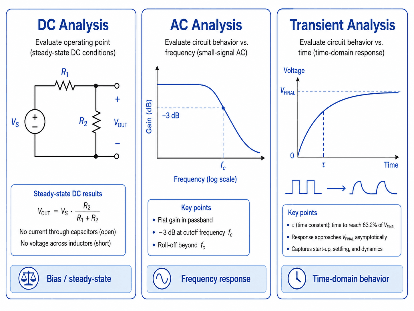
DC Analysis vs. AC Analysis vs. Transient Analysis
The most common beginner mistake is running the wrong type of simulation for the question being asked. DC analysis, AC analysis, and transient analysis are not three ways to get the same answer. Each one examines a different kind of circuit behavior.
| Simulation type | Best question to answer | Typical output | Common electronics use |
|---|---|---|---|
| Operating point | What are the steady voltages and currents with no changing input? | Node voltages, branch currents, device bias states | Transistor biasing, op-amp operating range, supply rail checks |
| DC sweep | How does the circuit change as an input voltage, current, or component value changes? | Output versus swept input or parameter | Transfer curves, diode behavior, logic thresholds, resistor value sensitivity |
| AC sweep | How does a small signal behave over frequency? | Gain, phase, cutoff frequency, bandwidth | Filters, amplifiers, feedback networks, impedance behavior |
| Transient analysis | How does the circuit behave over time? | Voltage and current waveforms versus time | Startup, switching, capacitor charging, pulses, settling, ringing |
| Monte Carlo or tolerance analysis | How much could results vary with real component tolerances? | Distribution of possible outcomes | Filter corners, reference dividers, timing circuits, gain tolerance |
| Noise or temperature analysis | How do non-ideal effects influence signal quality or operating point? | Noise contribution, drift, temperature-shifted behavior | Sensor front ends, precision analog circuits, low-level measurements |
AC analysis usually depends on the circuit’s DC operating point. If the bias point is wrong, the small-signal frequency response can also be misleading.
SPICE Simulation and Netlists
SPICE stands for Simulation Program with Integrated Circuit Emphasis. It is one of the most important circuit simulation methods in electronics because it can evaluate nonlinear DC behavior, small-signal AC behavior, and time-domain transient behavior for many circuit types.
In a SPICE-style workflow, the circuit is represented as a netlist. The netlist describes each component, the nodes it connects to, its value, and any device model it uses. Schematic tools often hide the netlist from the user, but the solver still needs the same information: connectivity, values, sources, models, and analysis commands.
| SPICE-style command or concept | What it means | When it is useful |
|---|---|---|
| \(.op\) | Operating point analysis | Checking bias voltages, device states, and steady currents before other simulations |
| \(.dc\) | DC sweep analysis | Sweeping an input source, supply voltage, or parameter to see how the circuit changes |
| \(.ac\) | Small-signal frequency sweep | Checking gain, phase, cutoff frequency, bandwidth, resonance, and filter response |
| \(.tran\) | Transient time-domain analysis | Checking startup, pulses, switching events, capacitor charging, delay, overshoot, and settling |
| Device model | Mathematical description of a real or ideal part | Capturing diode, transistor, MOSFET, op-amp, regulator, or IC behavior more realistically |
Before trusting a SPICE result, confirm that the model includes the behavior you care about. An op-amp simulation for a fast pulse should consider bandwidth, slew rate, output swing, input range, supply limits, and load current, not just ideal closed-loop gain.
Circuit Simulation Software and Tool Types
There is no single best circuit simulator for every user. The right tool depends on whether the goal is learning circuit behavior, validating an analog design, checking a manufacturer device model, building a PCB-connected schematic workflow, or evaluating layout-specific signal and power integrity effects.
| Tool type | Best for | Practical note |
|---|---|---|
| KiCad with ngspice | Open-source schematic-connected simulation and PCB design workflows | Useful when the circuit schematic and board design are part of the same project flow. |
| LTspice-style tools | Analog circuits, filters, power electronics, and manufacturer model testing | Common for learning SPICE behavior and testing real component models. |
| PSpice or OrCAD-style tools | Professional electronics design and commercial simulation workflows | Often used where documentation, model libraries, and design process control matter. |
| Multisim-style tools | Education, labs, and visual circuit learning | Good when users need a classroom-friendly circuit simulator with intuitive instruments. |
| Online visual simulators | Fast conceptual learning and simple circuit exploration | Helpful for beginners, but not a replacement for serious model validation or hardware testing. |
| Vendor model tools | Testing specific parts such as op-amps, regulators, MOSFETs, and converters | Best when the device model comes from the manufacturer and the design depends on real part behavior. |
| PCB signal and power integrity tools | Layout-level effects such as impedance, coupling, return paths, and rail behavior | Use when schematic-level SPICE is not enough to capture board-level behavior. |
A beginner may start with a visual or online circuit simulator, then move into SPICE-based tools as models and analysis requirements become more serious. A professional design often combines schematic simulation, datasheet review, PCB layout checks, and measured prototype validation.
How to Read Circuit Simulation Results
Simulation output is only useful when it is interpreted as an engineering decision. A waveform is not just a picture; it is evidence about voltage levels, current paths, component stress, timing, stability, or frequency behavior.
| Simulation result | What it tells you | What to check before trusting it |
|---|---|---|
| Node voltage | Bias levels, signal levels, logic thresholds, and output swing | Expected values, supply rails, common-mode range, and measurement point |
| Branch current | Current path, load behavior, and startup or switching spikes | Part current limits, source capability, diode/MOSFET stress, and load assumptions |
| Power dissipation | Component heating and stress | Resistor rating, IC package limits, MOSFET losses, and thermal margin |
| Frequency response | Gain, phase, cutoff frequency, bandwidth, resonance, and roll-off | Bias point, AC source setup, load impedance, and stability margin |
| Transient waveform | Startup, timing, switching, delay, overshoot, ringing, and settling | Timestep, initial conditions, realistic rise time, parasitics, and load conditions |
| Operating point | Device bias condition before signal behavior is evaluated | Saturation, cutoff, headroom, supply limits, and whether the active device is in the expected region |
A strong review checks more than the output node. For real design work, also inspect supply current, component voltage stress, resistor power, capacitor voltage rating, switch current, and whether active devices remain inside their datasheet operating limits.
What Controls the Accuracy of a Circuit Simulation?
The most realistic simulation is usually not the prettiest schematic. It is the model that includes the parts of the real circuit that affect the decision being made. For a simple homework voltage divider, ideal resistors may be enough. For a precision sensor input or high-speed switching node, ignored parasitics can completely change the answer.
| Modeling factor | Why it matters | Engineering implication |
|---|---|---|
| Ground reference | Most simulators need a clear reference node to solve voltages. | Missing or floating grounds can cause convergence errors or meaningless node voltages. |
| Component models | Ideal parts hide limits such as saturation, leakage, bandwidth, ESR, and thermal behavior. | Use realistic models when checking stress, timing, noise, stability, or precision. |
| Source impedance | Ideal voltage sources can supply unrealistic current unless limits are added. | Add realistic series resistance, source limits, or rise time when current spikes or startup behavior matter. |
| Load conditions | An unloaded output can look correct even when the real circuit must drive a sensor, ADC, cable, or amplifier input. | Include the load, probe, pull-up, pull-down, or downstream input impedance in the model. |
| Temperature and tolerance | Real components shift from nominal values and active devices drift with operating conditions. | Check worst-case values when the design depends on precision, bias margin, or timing. |
| Parasitics | PCB traces, leads, connectors, and packages add resistance, capacitance, and inductance. | High-speed, RF, switching, and precision circuits need layout-aware thinking. |
| Solver settings | Timestep, tolerance, and initial condition settings affect how time-domain behavior is calculated. | Do not assume a noisy, unstable, or overly smooth waveform is correct without checking solver setup. |
Simple Circuit Simulation Example: RC Step Response
A first-order RC circuit is a useful circuit simulation example because it can be checked with both simulation and hand calculation. The engineering question is simple: how fast does the output node rise after a step input?
1. Define the circuit and expected behavior
Assume a step voltage source drives a resistor, and the resistor charges a capacitor to ground. The output is measured across the capacitor. In an ideal first-order RC circuit, the time constant is controlled by \(R\) and \(C\).
2. Calculate the expected time constant
If \(R = 10\,k\Omega\) and \(C = 10\,nF\), the time constant is:
In a transient simulation, the capacitor voltage should reach about 63.2% of its final value after one time constant. After about five time constants, it should be very close to the final value.
3. Run transient analysis and compare the plot
The simulated waveform should rise smoothly toward the final voltage. If the waveform reaches 63.2% much earlier or later than \(100\,\mu s\), check the resistor value, capacitor value, output probe location, initial capacitor voltage, and whether a load is connected.
4. Change a value and predict the result
If the resistor doubles, the time constant doubles. If the capacitor is reduced by half, the time constant is cut in half. This is a useful way to confirm that the simulation responds the way the physical circuit should.
- \(R\) Resistance in the charging or discharging path, usually in ohms, kilohms, or megohms.
- \(C\) Capacitance being charged or discharged, commonly in pF, nF, µF, or F.
- \(\tau\) Time constant. In a simple RC step response, one time constant corresponds to about 63.2% of the final voltage.
For hands-on checks of the same concept, the RC Circuit Calculator can help verify time constant, cutoff frequency, and capacitor charging behavior, while the Voltage Divider Calculator is useful for simple DC divider checks before or after simulation.
Circuit Simulation Model Review Checklist
Before using a simulation result to make a design decision, review the model the same way an engineer reviews a calculation. The goal is not to make the simulation complicated; the goal is to include enough realism for the decision being made.
| Review check | What to look for | Why it matters |
|---|---|---|
| Question being answered | Bias point, frequency response, startup, switching event, tolerance spread, or stress check. | The simulation type must match the engineering decision. |
| Reference node | Every circuit needs a valid ground or reference node. | Floating circuits often fail to solve or produce misleading voltages. |
| Device model quality | Manufacturer model, generic model, ideal model, or simplified behavioral block. | The result cannot be more accurate than the model. |
| Loads and probes | Downstream input impedance, resistor loads, ADC input, cable, scope probe, or measurement circuit. | Real outputs are rarely unloaded. |
| Component stress | Current, power, voltage rating, thermal condition, and transient spikes. | A circuit can produce the desired waveform while overstressing a part. |
| Hand-calculation sanity check | Expected divider voltage, RC time constant, gain estimate, impedance, or cutoff frequency. | A simple independent estimate catches many schematic and unit mistakes. |
Engineering Judgment and Field Reality
Real circuits include effects that are easy to ignore in a clean schematic. Component tolerances shift resistor ratios and filter frequencies. Capacitors have leakage and equivalent series resistance. Inductors have winding resistance and saturation limits. PCB traces add small resistance, capacitance, and inductance. Measurement probes can load the circuit they are trying to observe.
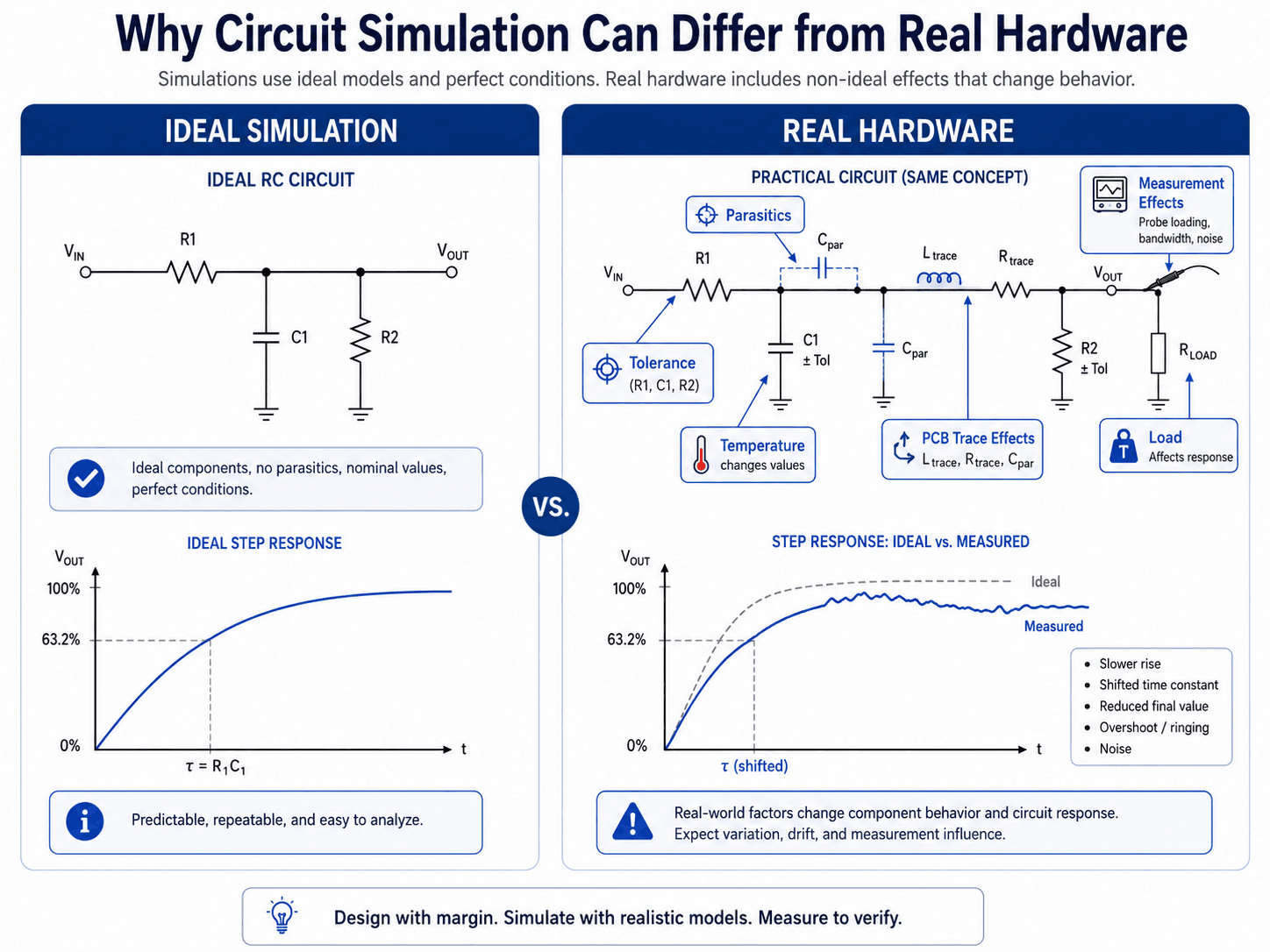
If the real circuit will operate near a limit, simulate with margin. A design that only works with nominal parts, perfect voltage rails, room temperature, and no parasitics is not a robust design.
Circuit Simulation vs. Breadboard vs. PCB Prototype
Circuit simulation is strongest early in the design process, but it does not replace every other validation step. Breadboards, PCB prototypes, and production testing each reveal different issues.
| Method | Best for | Main limitation |
|---|---|---|
| Simulation | Fast design exploration, model review, parameter sweeps, and early error detection | Depends on assumptions, models, and whether real-world effects are included |
| Breadboard | Quick physical checks for low-frequency and simple circuits | Poor for high-speed, low-noise, high-current, RF, or layout-sensitive circuits |
| PCB prototype | Testing layout, grounding, traces, connectors, thermal behavior, and manufacturability | Costs more time and money than simulation changes |
| Production validation | Confirming the final design against actual requirements, variation, and manufacturing conditions | Problems found this late are usually more expensive to fix |
When This Breaks Down
Circuit simulation becomes less reliable when the model leaves out the behavior that controls the real result. The problem is not that simulation is bad; the problem is that simplified models are sometimes used outside their useful range.
- High-speed signals: Trace length, impedance discontinuities, probe capacitance, package parasitics, and return paths can dominate the behavior.
- Power electronics: Switching transitions, diode recovery, MOSFET capacitance, transformer leakage, layout inductance, and thermal effects can change stress and ringing.
- Precision analog circuits: Offset voltage, bias current, temperature drift, noise, leakage, and tolerance can matter more than the ideal gain equation.
- Digital interfaces: Edge rate, input thresholds, pull-up strength, capacitive loading, and timing margins can make “logic high” and “logic low” more nuanced than the schematic suggests.
- PCB-level effects: Signal integrity, power integrity, return paths, coupling, EMI, and RF behavior may require layout-aware or electromagnetic simulation beyond basic SPICE.
- Unvalidated models: A third-party or generic model may not include all device limits, especially for behavior outside a normal operating range.
Common Circuit Simulation Mistakes and Practical Checks
Most simulation problems are setup problems. When a result looks impossible, unstable, or too perfect, start by checking the model before assuming the circuit behavior is real.
| Mistake | Typical symptom | Practical check |
|---|---|---|
| Missing ground reference | Simulation fails, nodes float, or voltages are undefined. | Confirm the schematic has a clear reference node. |
| Using ideal sources everywhere | Unrealistic current spikes or perfect waveforms. | Add source resistance, current limits, rise time, or realistic supply behavior. |
| Trusting a generic active-device model | Op-amp, MOSFET, diode, or regulator behavior seems too clean. | Use a model appropriate for the actual part and operating range. |
| Ignoring component tolerance | Only one ideal result is reviewed. | Check worst-case values or run tolerance-based simulations when the design depends on precision. |
| Reading plots without checking units | Wrong interpretation of mV vs V, µs vs ms, or dB vs linear gain. | Verify axis units, scaling, and probe points before making a decision. |
| Skipping power checks | Waveform looks correct but components are overloaded. | Plot or calculate current and power, not just voltage. |
Do not treat a successful simulation run as a successful design review. A simulator can return a clean waveform even when the circuit is sensitive, overstressed, poorly modeled, or difficult to build.
Why Circuit Simulations Fail or Do Not Converge
Convergence problems happen when the simulator cannot settle on a valid mathematical solution. This is common in circuits with floating nodes, unrealistic ideal sources, discontinuous switching behavior, or poor initial conditions.
| Symptom | Likely cause | Practical fix |
|---|---|---|
| Simulation will not start | Missing ground, floating node, or unconnected pin | Add a reference node and check every connection. |
| Operating point fails | Unrealistic ideal source, impossible bias condition, or unstable circuit state | Add realistic resistance, check device orientation, and simplify the circuit. |
| Transient simulation stops early | Timestep too aggressive, abrupt switching, or stiff circuit behavior | Adjust timestep, add realistic rise/fall time, or include small parasitic elements. |
| Waveform has unrealistic spikes | Ideal switching, missing parasitics, or solver artifacts | Add source impedance, ESR, ESL, snubbers, or layout-relevant parasitics where appropriate. |
| AC response looks impossible | Wrong bias point, wrong AC source setup, or incorrect model terminals | Run operating point first and verify the small-signal source configuration. |
| Results change wildly with tiny settings changes | Numerically sensitive model or unstable circuit condition | Check the model, simplify the circuit, and verify expected behavior with hand estimates. |
Useful Reference for SPICE-Based Simulation
For readers who want to see how circuit simulation is implemented in a real electronics design workflow, official software documentation is usually more useful than a broad definition page.
- KiCad SPICE simulation documentation: KiCad SPICE simulation integration explains how ngspice is integrated with schematic capture, how simulations can be configured, and how voltage and current probes are used to inspect results.
- Project-specific criteria: For professional electronics work, simulation should also be checked against datasheets, test requirements, PCB layout constraints, reliability targets, and prototype measurements.
- Engineering use: Use official tool documentation to understand what the simulator can calculate, then use engineering review to decide whether the model is realistic enough for the design decision.
Frequently Asked Questions
Circuit simulation is used to predict circuit behavior before hardware is built. Engineers use it to check node voltages, branch currents, timing response, frequency response, component stress, power dissipation, and design sensitivity before moving to PCB layout, breadboarding, or prototype testing.
SPICE is one of the most widely used methods for analog circuit simulation, but circuit simulation is the broader idea. A circuit simulator may use SPICE or a related solver to run operating point, DC sweep, AC sweep, transient, noise, and tolerance-based analyses.
Circuit simulation cannot fully replace breadboarding or prototype testing. Simulation is excellent for finding design problems early, but real hardware still includes component tolerance, parasitic capacitance and inductance, PCB trace effects, thermal drift, measurement loading, and manufacturing variation.
A circuit simulation may fail to converge because of missing grounds, floating nodes, unrealistic ideal sources, discontinuous device models, poor initial conditions, extremely small or large component values, or a circuit operating near an unstable point. The fix is usually to simplify the model, add realistic parasitics, check references, and verify device models.
Circuit simulation usually focuses on schematic-level electrical behavior, while PCB simulation may include layout-specific effects such as trace impedance, coupling, return paths, signal integrity, power integrity, and electromagnetic behavior. Critical designs often need both.
Summary and Next Steps
Circuit simulation is one of the most useful tools in electronics engineering because it lets designers predict circuit behavior before building hardware. It turns a schematic and component models into voltage, current, timing, frequency, and stress results that can guide real design decisions.
The key is choosing the right analysis type, checking the model, and interpreting results with engineering judgment. DC, AC, and transient simulations answer different questions, and every result should be reviewed against expected behavior, component limits, parasitics, tolerance, and real measurement conditions.
Where to go next
Continue your learning path with related Turn2Engineering resources.
-
Electronics Engineering
Build broader context around circuits, electronic devices, embedded hardware, sensors, and PCB design workflows.
-
Prototyping in Electronics
Compare simulation-based design work with physical prototyping, test builds, and hardware validation.
-
Impedance Calculator
Explore AC circuit impedance, reactance, phase angle, and frequency-dependent behavior.