Key Takeaways
- Core idea: Short circuit analysis calculates fault current at specific points in a power system when a low-impedance fault path appears.
- Engineering use: Engineers use the results to check breaker interrupting duty, switchgear withstand, fuse ratings, relay settings, coordination, and safety studies.
- What controls it: Available fault current is controlled by source strength, transformer impedance, conductor impedance, motor or generator contribution, grounding, and fault type.
- Practical check: A simple transformer calculation is useful for estimating, but a real study must review maximum and minimum fault cases across credible operating configurations.
Table of Contents
Introduction
Short circuit analysis is the process of calculating available fault current in a power system when conductors or equipment are unintentionally connected through a low-impedance path. The result helps engineers verify whether breakers, fuses, switchgear, buses, cables, transformers, and protection settings can safely withstand or interrupt credible fault conditions.
Fault Current Path in a Power System

Read the diagram from left to right: source strength, transformer percent impedance, breaker location, feeder impedance, and fault location all influence the available short-circuit current at that point in the system.
What Is Short Circuit Analysis?
Short circuit analysis is a power system study used to estimate the current that flows during faults such as three-phase faults, line-to-line faults, line-to-ground faults, and double line-to-ground faults. Instead of studying normal load current, the analysis studies abnormal current paths that can stress equipment far beyond normal operating levels.
The key output is usually the available fault current at buses, switchgear, panelboards, transformers, feeders, motor control centers, and other equipment locations. A complete study is typically performed at multiple buses, not just one point, because the available current changes as impedance is added through transformers, cables, busways, reactors, and downstream equipment.
A short circuit study should answer two questions: can the equipment safely carry or interrupt the fault, and will the correct protective device operate fast enough for the selected fault case?
Types of Faults Evaluated in Short Circuit Analysis
Short circuit analysis is not one single calculation. The engineer chooses the fault type because balanced and unbalanced faults stress the system in different ways. A three-phase bolted fault is often used for maximum symmetrical current checks, while ground faults and line-to-line faults are important for relay sensitivity, grounding behavior, and protection coordination.
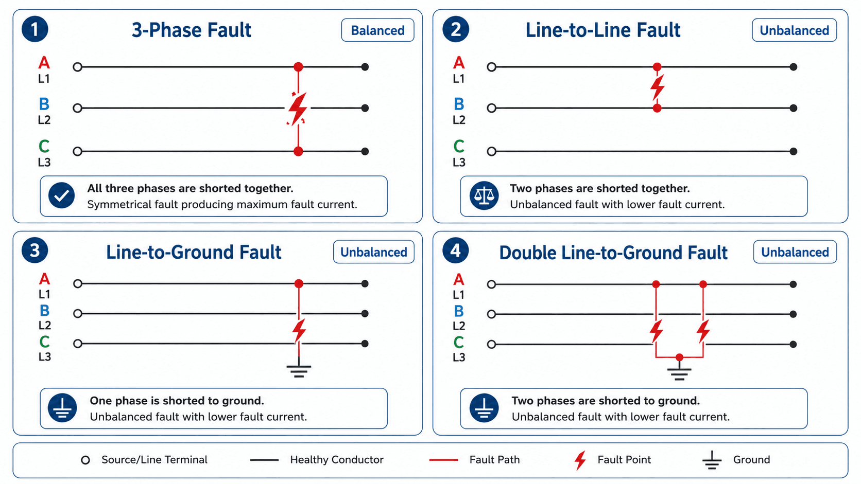
| Fault type | What is shorted | Why engineers analyze it |
|---|---|---|
| Three-phase fault | All three phases are connected together, usually modeled as a balanced fault. | Commonly used for maximum symmetrical current, interrupting duty, and equipment withstand checks. |
| Line-to-line fault | Two phases are connected without a ground path. | Important for unbalanced fault behavior and phase protection sensitivity. |
| Line-to-ground fault | One phase is connected to ground or a grounded object. | Critical for grounding studies, ground-fault relay settings, and zero-sequence current paths. |
| Double line-to-ground fault | Two phases are connected to ground. | Used to evaluate unbalanced ground fault conditions and protection response in grounded systems. |
Unbalanced faults often require sequence-network thinking because the positive, negative, and zero-sequence paths may behave differently. Grounded-wye, delta, high-resistance grounded, and impedance-grounded systems can produce very different ground-fault currents even when the line-to-line voltage is the same.
How Short Circuit Current Is Calculated
The basic idea is simple: fault current rises when system voltage is high and total impedance to the fault is low. The engineering challenge is building a credible impedance model. A complete model may include utility source impedance, transformer impedance, cable impedance, motor contribution, generator contribution, grounding method, and the selected network operating condition.
For a balanced three-phase fault, this simplified expression uses line-to-line voltage and the equivalent per-phase impedance to the fault. It is useful for concept-level understanding, but detailed studies use per-unit methods, symmetrical components, or software-based network models depending on the fault type and calculation method being applied.
- \(I_{sc}\) Calculated short circuit current, typically reported in amperes or kiloamperes.
- \(V_{LL}\) Line-to-line system voltage at the faulted bus or equipment location.
- \(Z_{total}\) Total equivalent per-phase impedance from all sources feeding the fault to the fault point.
Transformer-Based Fault Current Estimate
For a quick transformer-secondary estimate, engineers often start with transformer full-load current and percent impedance. This is not a complete study, but it is useful for understanding why transformer impedance strongly affects downstream available fault current.
A transformer with lower percent impedance allows more fault current to pass through. A transformer with higher percent impedance limits the downstream fault current. This is why transformer nameplate data is one of the first items checked in a short circuit model.
Symmetrical, Asymmetrical, and Peak Fault Current
Short circuit studies often distinguish between symmetrical RMS current, asymmetrical current, and peak current. The symmetrical RMS value is commonly used for interrupting-duty comparisons, while asymmetrical and peak current relate to the DC offset in the waveform. The system X/R ratio affects that offset, which can increase momentary and close-and-latch duty even when the symmetrical current appears acceptable.
A breaker, fuse, or switchgear assembly may need to satisfy more than one short-circuit duty. Do not assume that passing a symmetrical RMS current check automatically satisfies momentary, peak, or short-time withstand requirements.
Worked Example: Transformer Short Circuit Current Calculation
A transformer-only calculation is one of the simplest ways to estimate available three-phase fault current at a transformer secondary. The example below is useful for learning the method, but it does not replace a full short circuit study because it ignores utility source impedance, conductor impedance, motor contribution, and operating configuration.
Example inputs
- Transformer size: 1500 kVA
- Secondary voltage: 480 V, three-phase
- Transformer impedance: 5.75%
- Assumption: simplified transformer-secondary three-phase bolted fault estimate
First calculate the transformer full-load current:
Then divide the full-load current by the transformer impedance expressed as a decimal:
Engineering interpretation
Under this simplified transformer-only assumption, the transformer secondary could have roughly 31.4 kA of available three-phase fault current. The actual current at downstream panels would usually be lower after feeder impedance is included, while motor contribution, generator contribution, or parallel sources may increase certain duties.
This example is a screening calculation. A real equipment-duty study should verify source impedance, transformer data, cable lengths, motor contribution, generator contribution, X/R ratio, and all credible switching configurations before relying on the result.
Short Circuit Current Calculation Workflow
A reliable short circuit study is a workflow, not just a formula. The engineer first defines the source and network model, then selects fault cases, calculates currents, and compares the results with the equipment that must sense, carry, or interrupt the fault.
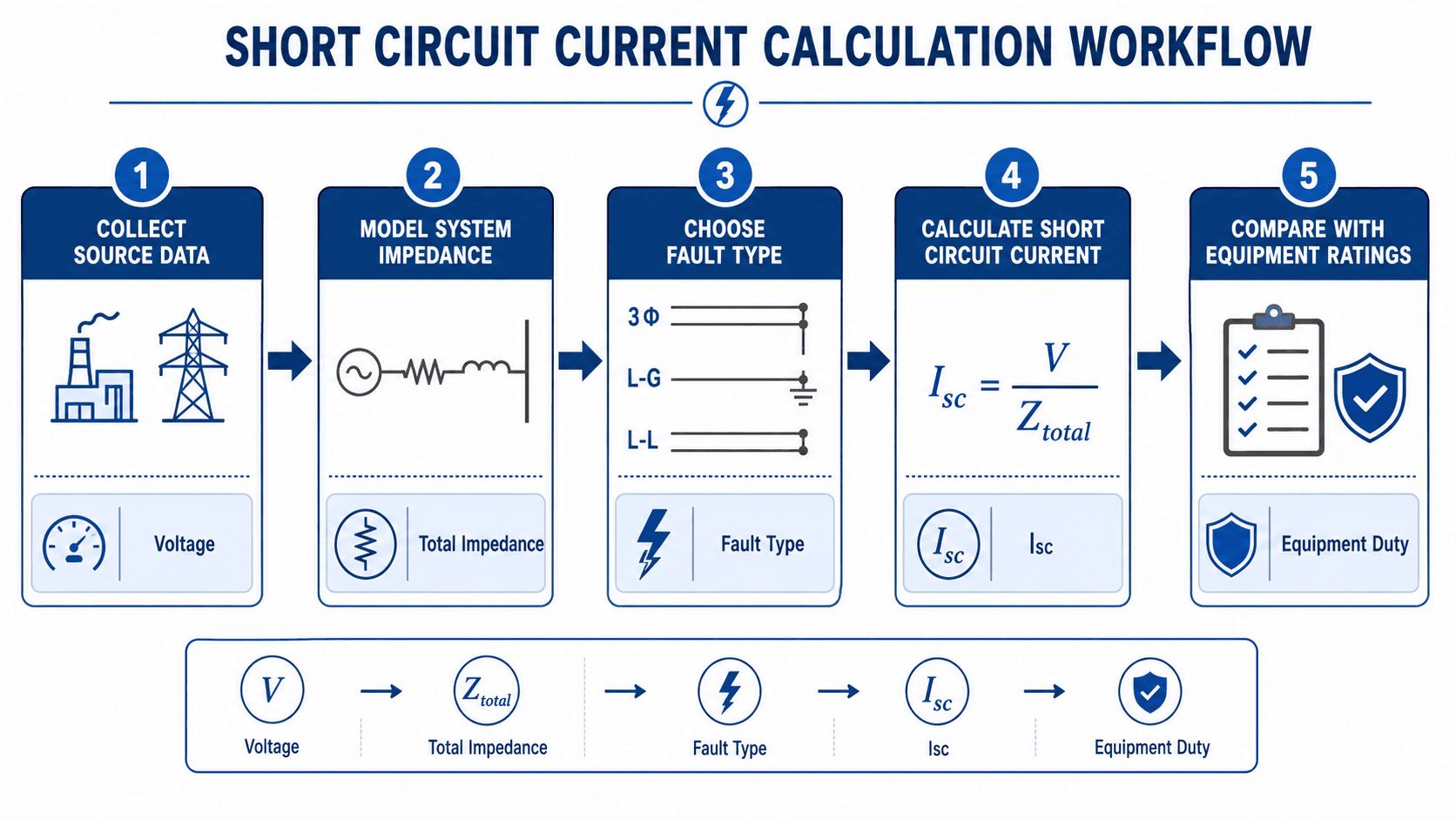
- Collect source data: utility available fault current, source impedance, generator data, and upstream system assumptions.
- Build the impedance model: include transformers, conductors, busways, reactors, motors, generators, and grounding paths where relevant.
- Select fault types and locations: study buses, switchgear, panelboards, MCCs, feeders, and equipment terminals that need duty checks.
- Run maximum and minimum cases: maximum cases support equipment duty checks; minimum cases support protective device sensitivity and clearing review.
- Compare results with ratings: evaluate interrupting rating, momentary duty, short-time withstand, fuse duty, relay response, and coordination.
Short circuit software can only calculate what the model describes. Verify utility source data, transformer impedance, conductor lengths, grounding method, motor contribution, and switching configuration before relying on equipment duty reports.
How Short Circuit Analysis Results Are Used for Equipment Duty
Short circuit results become useful when they are compared with equipment ratings and protection requirements. The calculated current by itself does not say whether a system is acceptable. The key engineering question is whether each device and assembly can safely handle the fault until the protective device clears it.
In building and facility applications, short circuit analysis is especially important for low voltage power systems, where panelboards, MCCs, switchboards, busways, and downstream equipment must be checked against available fault current at their installed locations.
| Engineering use | What the short circuit result checks | Practical implication |
|---|---|---|
| Breaker interrupting rating | Whether the breaker can interrupt the calculated fault current at its voltage rating. | An underrated breaker may fail violently or fail to clear the fault safely. |
| Switchgear and panelboard duty | Whether the equipment can withstand momentary and short-time fault stresses. | Bus bracing, enclosure rating, and equipment labeling must match credible fault levels. |
| Fuse selection | Whether the fuse can safely interrupt the available current and coordinate with downstream devices. | The fuse must clear the fault without exceeding its interrupting capacity or compromising selectivity. |
| Relay settings | Whether pickup, time delay, instantaneous, ground, or directional elements detect the intended fault cases. | Settings must balance speed, sensitivity, selectivity, dependability, and security. |
| Arc flash inputs | Available fault current and expected protective device clearing behavior. | Fault current is one input to incident energy analysis, but clearing time and equipment configuration also matter. |
Always compare calculated fault current with the rating of the actual installed equipment, not only the rating of a replacement part or a generic device family.
Maximum vs Minimum Short Circuit Current
A strong study does not only search for the largest number. Maximum and minimum fault currents answer different engineering questions. The maximum case checks whether equipment can survive or interrupt the fault. The minimum case checks whether protection can detect and clear a weaker fault quickly enough.
| Case | Typical purpose | What can change the result |
|---|---|---|
| Maximum fault current | Breaker interrupting duty, switchgear withstand, bus bracing, fuse interrupting capacity, and equipment labeling. | Strong utility source, parallel transformers, closed ties, large motors, generators, and low-impedance paths. |
| Minimum fault current | Protective device sensitivity, relay pickup, fuse clearing, ground fault detection, and backup protection review. | Weak source conditions, long feeders, higher impedance, open ties, generator-limited operation, and high-resistance faults. |
This distinction is especially important for long feeders and grounded systems. A downstream ground fault may be much lower than the three-phase bolted fault current at the service entrance, but it may still be the fault that determines whether protection is sensitive enough.
Short Circuit Study Review Checklist
The best short circuit analysis is only as good as the model behind it. Use this checklist as a senior-engineer-style review before trusting calculated fault currents for equipment duty, coordination, or safety decisions.
Start with the source assumption, verify transformer and conductor data, review all credible switching configurations, then compare each calculated duty with the actual installed equipment rating.
| Review check | What to look for | Why it matters |
|---|---|---|
| Utility source data | Available fault current, source impedance, X/R ratio, and whether values represent maximum or minimum conditions. | Bad source data can make every downstream duty result unreliable. |
| Transformer nameplate values | kVA, primary and secondary voltage, connection, grounding, percent impedance, and parallel operation. | Transformer impedance is often the dominant current-limiting element in facility studies. |
| Feeder and bus impedance | Conductor size, material, length, raceway assumptions, busway data, and cable routing. | Downstream fault current can drop significantly when long feeders are modeled correctly. |
| Motor and generator contribution | Large induction motors, synchronous machines, standby generators, and distributed generation sources. | Rotating machines and local sources can raise initial fault current or change momentary duty. |
| Operating configurations | Normal, emergency, tie-closed, tie-open, maintenance, parallel transformer, and generator-backed cases. | The worst equipment duty case may not be the everyday operating configuration. |
| Protective device settings | Overcurrent pickup, time delay, instantaneous settings, ground elements, and time-current curve coordination. | Fault current results must support both fast fault clearing and selective isolation of the correct device. |
| Equipment rating comparison | Breaker interrupting rating, switchgear withstand, panel SCCR, fuse rating, relay settings, and labels. | The study must connect calculated current to specific installed equipment limits. |
Engineering Judgment and Field Reality
Field conditions often make short circuit analysis more complicated than the clean one-line diagram suggests. Existing facilities may have incomplete conductor lengths, replacement breakers with different ratings, field-modified switchgear, undocumented tie positions, old transformer nameplates, or generators that are operated differently than the original design assumed.
Modern systems can also include inverter-based resources, variable frequency drives, UPS systems, distributed generation, and microgrid controls. These sources may not contribute fault current the same way a utility source or rotating machine does. The engineer must understand whether a simplified calculation is only a screening estimate or whether a more detailed model is required.
The dangerous mistake is treating a calculated fault current as a universal property of the building. Available fault current changes by location, operating configuration, source condition, and equipment state.
Where This Method Breaks Down
Simple short circuit formulas are useful for learning and rough estimating, but they break down when the system has multiple sources, nontrivial grounding, long feeders, motor contribution, generator contribution, power electronics, or several operating configurations. In those cases, the calculation becomes a network modeling problem.
- Multiple sources: utility feeds, generators, and large motors may all contribute current to the same fault.
- Unbalanced ground faults: zero-sequence paths, transformer connections, and grounding impedance strongly affect the result.
- Long downstream circuits: cable impedance can make fault current much lower than a transformer-secondary estimate suggests.
- Power-electronic sources: inverter-based resources, UPS systems, and drives may limit current based on controls rather than traditional machine reactance.
- Changing configurations: tie breakers, maintenance switching, standby generation, and parallel transformers can create different maximum and minimum cases.
Common Mistakes and Practical Checks
Most short circuit analysis errors come from model assumptions, not the arithmetic. A spreadsheet may produce a precise number, but that number is only useful if the input data, system configuration, and equipment comparison are correct.
- Using an infinite bus assumption without checking source data: this can overstate fault current and hide the difference between realistic utility conditions and a simplified estimate.
- Ignoring motor contribution: large motors can feed the fault for a short period and affect momentary duty.
- Using load current as if it limits fault current: fault current is limited primarily by source and circuit impedance, not by normal connected load.
- Forgetting minimum fault current: protection that looks acceptable at maximum fault current may be too slow or insensitive for low-current downstream faults.
- Not checking equipment SCCR or withstand ratings: downstream panels, MCCs, switchboards, fuses, and busways may have their own short-circuit current ratings.
Do not use a transformer-only fault current estimate as proof that every downstream device is properly rated. Each equipment location should be reviewed against the available fault current at that specific point.
Standards and Design References for Short Circuit Studies
Short circuit analysis should be tied to recognized engineering practice when the results affect equipment duty, protection, or safety decisions. Standards and design references help define calculation methods, equipment duty concepts, current definitions, and practical modeling assumptions.
- IEEE Std 551: IEEE recommended practice for calculating short-circuit currents provides a recognized framework for understanding short-circuit current duties in industrial and commercial power systems. It is useful when study results affect equipment interrupting ratings, withstand ratings, relay settings, or protection review.
- IEC 60909 context: IEC 60909 is another widely used short-circuit calculation framework, especially for three-phase AC systems and international projects.
- Project-specific criteria: Equipment ratings, owner standards, utility data, coordination requirements, and local review requirements may control how the study is performed and documented.
- Engineering use: Engineers use recognized references to choose calculation assumptions, compare device duties, document cases, and review whether modeled results are appropriate for the actual system.
Frequently Asked Questions
Short circuit analysis is used to calculate available fault current at different points in a power system. Engineers use those results to check breaker interrupting ratings, switchgear withstand ratings, fuse duties, relay settings, protective coordination, and related safety studies.
A simplified balanced three-phase short circuit estimate is fault current equal to line-to-line voltage divided by the square root of three times the equivalent per-phase impedance to the fault. Complete studies also include source impedance, transformer impedance, conductor impedance, motor contribution, generator contribution, grounding, and the selected fault type.
Short circuit current is a type of fault current that flows when a low-impedance connection occurs between phases, phase and ground, or multiple conductors. In many power system discussions, fault current and short circuit current are used almost interchangeably, but fault current can also describe broader abnormal-current conditions depending on context.
No. Short circuit analysis calculates available fault current and equipment duty. Arc flash analysis uses fault current along with protective device clearing time, working distance, equipment configuration, and other assumptions to estimate incident energy.
Transformer impedance is important because it limits how much fault current can flow from the source to the downstream system. A lower percent impedance transformer generally produces higher available fault current on the secondary side, while a higher percent impedance transformer reduces the fault current.
Summary and Next Steps
Short circuit analysis calculates available fault current so engineers can evaluate equipment duty, protection settings, and the behavior of a power system under abnormal fault conditions. It is one of the core studies that connects power system modeling to real equipment ratings and protective device performance.
The most important ideas are the fault current path, total system impedance, fault type, maximum and minimum fault cases, and the comparison between calculated current and actual equipment ratings. A clean one-line diagram and a careful model review are just as important as the equation.
Where to go next
Continue your learning path with related Turn2Engineering resources.
-
Load Flow Analysis
Compare normal steady-state power system studies with fault-current studies used for equipment duty and protection review.
-
Protective Relays
Learn how relays detect abnormal current, voltage, impedance, or differential conditions and issue trip commands.
-
Overcurrent Protection
Review how breakers, fuses, and overcurrent devices respond to excessive current and fault conditions.