Key Takeaways
- Core idea: Seismic design helps structures resist earthquake ground motion by controlling strength, stiffness, ductility, drift, stability, and load path.
- Engineering use: Engineers use seismic design to select lateral systems, calculate seismic demands, detail ductile elements, and protect life safety during earthquake shaking.
- What controls it: Ground motion, site class, building mass, structural system, response modification factor, height, irregularities, and diaphragm behavior often control the design.
- Practical check: A strong member does not guarantee good seismic performance if the load path, connections, detailing, or foundation response is weak.
Table of Contents
Introduction
Seismic design is the process of designing buildings and structures to resist earthquake ground motion. It combines structural analysis, lateral load paths, ductile detailing, site-specific ground motion, foundation behavior, and code-based design checks so a structure can protect occupants and avoid sudden collapse during severe shaking.
How Seismic Design Works
Notice that seismic design is not only about making individual members stronger. The structure must move earthquake forces through a continuous system while allowing controlled deformation instead of brittle failure.
What is Seismic Design?
Seismic design is a branch of structural engineering focused on how buildings, bridges, and other structures behave during earthquakes. Unlike ordinary gravity design, which mainly resists vertical loads, seismic design addresses horizontal inertial forces, cyclic loading, drift, torsion, foundation movement, and damage patterns caused by shaking.
A useful way to think about seismic design is that the ground moves first, the foundation follows, and the mass of the building resists that motion because of inertia. This creates forces and deformations throughout the structure. Good seismic design gives those forces a reliable path to the ground while detailing the structure so critical elements can deform without sudden loss of capacity.
In structural engineering, seismic design is closely connected to structural loads, structural analysis, lateral load paths, materials, foundations, and code requirements. The final design is not just a calculation; it is a system-level decision about how the building should respond when the ground shakes.
How Earthquakes Affect Structures
Earthquakes create ground acceleration. When the ground moves, the foundation moves with it, but the building mass tends to lag behind. This difference between ground motion and structural inertia creates lateral forces, story drift, diaphragm forces, overturning, torsion, and connection demands.
Mass creates seismic force
Heavier structures usually attract larger seismic forces because seismic demand is tied to effective seismic weight. This is why nonstructural components, heavy cladding, rooftop equipment, storage loads, and mechanical systems matter. A building can have a strong frame but still perform poorly if heavy components are not anchored or if added mass was ignored.
Stiffness changes force distribution
Stiffer elements attract more load, especially when they are arranged irregularly. A stiff shear wall on one side of a building can reduce drift locally but also introduce torsion if the center of rigidity is far from the center of mass. Seismic design therefore evaluates both strength and stiffness distribution.
Ductility controls how damage develops
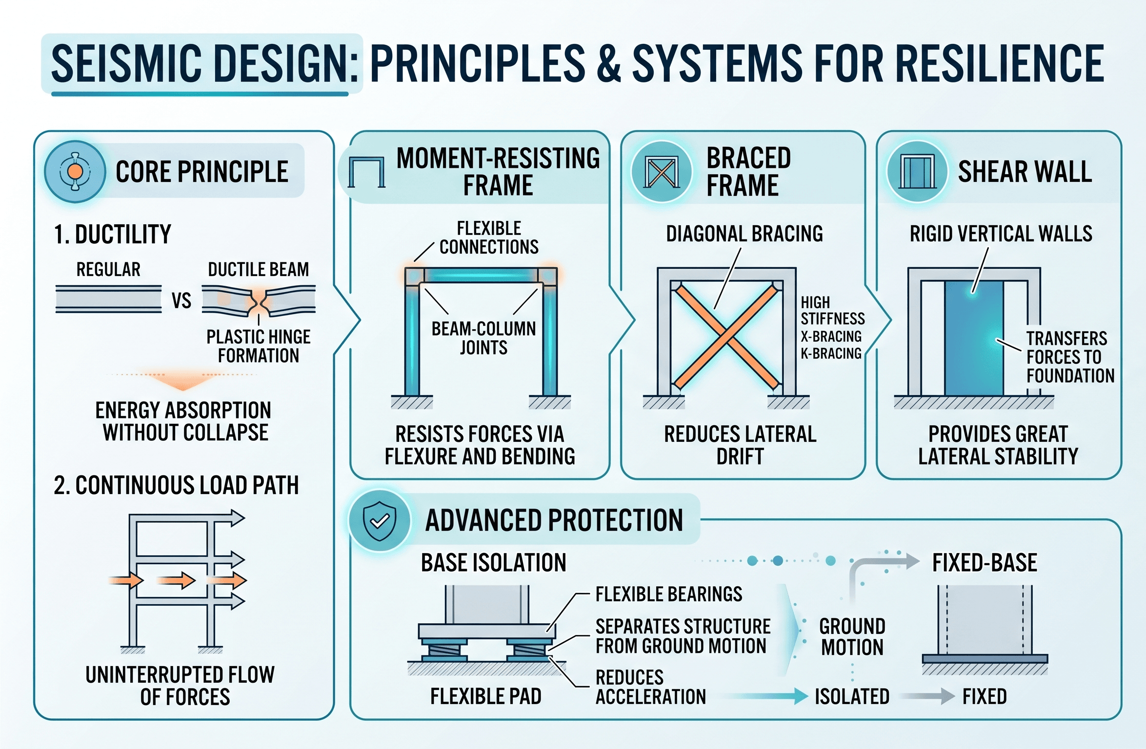
Ductility is the ability to deform in a controlled way without brittle failure. In seismic design, ductile behavior is often more valuable than simply making every element oversized. Proper confinement reinforcement, steel connection detailing, brace behavior, diaphragm anchorage, and capacity design principles help the structure dissipate energy without sudden collapse.
How Engineers Use Seismic Design
Engineers use seismic design to translate earthquake hazard into practical building decisions. The process affects the structural system, member sizes, connection details, foundation design, diaphragm layout, nonstructural anchorage, and construction documents.
- Selecting a seismic force-resisting system such as shear walls, braced frames, moment frames, dual systems, or base isolation.
- Determining seismic design category, design spectral response accelerations, effective seismic weight, base shear, vertical force distribution, and drift demands.
- Reviewing irregularities, soft stories, discontinuous walls, transfer levels, torsional behavior, diaphragm flexibility, and foundation load transfer.
- Coordinating architectural openings, mechanical penetrations, stairs, elevators, façades, and rooftop equipment so they do not interrupt the seismic load path.
Before accepting a seismic concept, trace the lateral force path from building mass into diaphragms, collectors, vertical resisting elements, foundations, and soil. If any step is vague, discontinuous, or dependent on a brittle connection, the design needs more review.
What Controls Seismic Design?
Seismic design is controlled by a combination of site hazard, soil response, building use, mass, geometry, structural system, material behavior, and detailing. The controlling issue is not always the largest force; in many buildings, drift, torsion, diaphragm transfer, connection ductility, or foundation compatibility becomes more important than simple member strength.
| Factor | Why it matters | Engineering implication |
|---|---|---|
| Ground motion hazard | Earthquake intensity varies by location and seismic source region. | Controls mapped acceleration values, design spectrum, and seismic force level. |
| Site class and soil behavior | Soft soils can amplify shaking, lengthen periods, and create foundation movement concerns. | A geotechnical report can change design accelerations, foundation strategy, and detailing requirements. |
| Effective seismic weight | More mass generally creates greater inertial demand during shaking. | Heavy systems, cladding, storage, and equipment must be included correctly. |
| Structural system | Shear walls, braced frames, and moment frames resist forces differently. | System choice affects stiffness, ductility, response modification factor, drift, and constructability. |
| Building irregularities | Soft stories, reentrant corners, offsets, and discontinuities concentrate damage. | Irregular buildings often need more detailed analysis, stronger collectors, and careful detailing. |
| Connection and detailing quality | Seismic loads reverse direction and cycle repeatedly during shaking. | Brittle connections, poor anchorage, and inadequate confinement can control performance. |
Seismic Loads and Base Shear
Many introductory seismic design workflows begin with an equivalent lateral force concept. A simplified form of the seismic base shear equation is:
This equation shows the basic relationship between seismic demand and building weight. The design base shear \(V\) increases as the effective seismic weight \(W\) increases and as the seismic response coefficient \(C_s\) increases. In actual building design, \(C_s\) depends on code-defined parameters such as design spectral acceleration, structural period, risk category, importance factor, response modification coefficient, and system limitations.
- \(V\) Seismic base shear, or the total design lateral force applied at the base of the structure.
- \(C_s\) Seismic response coefficient, influenced by spectral acceleration, structural system, period, importance, and code limits.
- \(W\) Effective seismic weight, including structural dead load and other code-defined portions of permanent or applicable loads.
- \(S_{DS}\) Design spectral response acceleration at short periods, commonly important for stiff, low-period structures.
- \(S_{D1}\) Design spectral response acceleration at a 1-second period, commonly important for more flexible or taller structures.
The equation is useful for learning because it makes one point clear: seismic design is not only about earthquake location. The building’s own mass, stiffness, period, system type, and detailing strongly influence the final design demand.
Seismic Design Review Workflow
A useful seismic design review follows the force path and checks whether the analysis assumptions match the building that will actually be constructed. The workflow below is written as a practical senior-review sequence rather than a code substitute.
Start with the site hazard and soil class. Determine the building use, risk category, mass, and seismic design category. Select the lateral system. Trace diaphragm forces into collectors, frames or walls, foundations, and soil. Then review drift, torsion, irregularities, connection ductility, nonstructural anchorage, and construction details.
| Check or decision | What to look for | Why it matters |
|---|---|---|
| Confirm site inputs | Correct location, risk category, site class, mapped hazard, and design spectral values. | Incorrect seismic inputs can affect every downstream force, drift, and detailing decision. |
| Trace the load path | Mass to diaphragm, diaphragm to collectors, collectors to vertical system, vertical system to foundation. | Seismic failures often occur where the force path is interrupted, weak, brittle, or poorly detailed. |
| Check irregularities | Soft stories, setbacks, reentrant corners, torsion, discontinuous walls, transfer diaphragms, and offsets. | Irregularities can concentrate deformation and invalidate overly simple analysis assumptions. |
| Review drift and deformation | Story drift, P-delta effects, façade compatibility, stair/elevator interaction, and partition damage. | A structure can have adequate strength but still perform poorly if deformation is uncontrolled. |
| Review ductile detailing | Confinement steel, steel connection behavior, brace buckling, anchorage, collectors, chords, and boundary elements. | Seismic performance depends on controlled yielding and energy dissipation, not brittle fracture. |
| Coordinate nonstructural components | Mechanical equipment, ceilings, piping, cladding, parapets, storage racks, and rooftop units. | Nonstructural failures can create life-safety hazards even when the primary frame remains standing. |
Example: Choosing a Seismic Force-Resisting System
Consider a mid-rise building in a region with moderate to high seismic demand. The architect wants open floor plates, the owner wants cost efficiency, and the engineer needs to control drift, torsion, and damage. The seismic design decision is not simply “make the columns larger.” The team must select a lateral system that fits the layout and provides a clear path to the foundation.
Possible system choices
Reinforced concrete shear walls may provide high stiffness and efficient drift control, but they can conflict with open architectural layouts. Steel braced frames can be efficient and economical, but brace locations may interfere with windows, doors, or circulation. Moment frames preserve open bays but often require larger members, stronger connections, and careful drift checks.
Engineering interpretation
The best seismic system is usually the one that balances structural performance, architectural coordination, constructability, foundation demands, and ductile detailing. A theoretically efficient system can become a poor choice if it creates discontinuous load paths, large transfer forces, excessive torsion, or connection details that are difficult to build correctly.
Engineering Judgment and Field Reality
Real seismic performance depends on details that are easy to miss in simplified diagrams. Diaphragm openings, collector connections, wall boundary elements, anchor rods, weld access, rebar congestion, slab edges, construction joints, and foundation embedment can control how earthquake forces actually move through the structure.
Field changes are especially important. A new opening through a diaphragm, relocated brace, omitted drag strut, changed rooftop unit, or modified shear wall boundary can alter the seismic load path. In existing buildings, drawings may not match field conditions, and older structures may lack the ductile detailing expected in modern seismic design.
Seismic design often fails at interfaces: diaphragm-to-wall connections, collector splices, wall-to-foundation anchorage, brace gusset details, mechanical equipment supports, and transfer levels. These details may look secondary on drawings, but they are often where earthquake demand becomes concentrated.
When This Breaks Down
Simplified seismic design explanations break down when the structure is irregular, the soil response is complex, the building is tall or flexible, or the intended performance objective goes beyond ordinary life-safety design. In those cases, simple lateral force procedures may not capture the full behavior.
- Highly irregular buildings may need modal response spectrum analysis, nonlinear analysis, or more advanced review of torsion and deformation compatibility.
- Soft or liquefiable soils can change foundation behavior and amplify shaking in ways that require geotechnical coordination.
- Transfer levels, podium structures, discontinuous walls, and setbacks can concentrate forces into collectors, diaphragms, and vertical elements.
- Existing buildings may have brittle detailing, weak unreinforced masonry, poor anchorage, or undocumented modifications that are not obvious from a basic visual review.
- Performance-based design, essential facilities, and tall buildings often require deeper analysis than a basic code-level force calculation.
Common Mistakes and Practical Checks
Many seismic design mistakes happen when the structure is treated as a set of isolated members instead of a connected dynamic system. Good seismic review looks for weak links, discontinuities, stiffness imbalances, and brittle behavior.
- Ignoring the diaphragm and collector system even though it must deliver inertial forces into the lateral system.
- Assuming a stiff wall or frame improves performance without checking torsion, compatibility, and foundation transfer.
- Underestimating nonstructural seismic hazards such as parapets, cladding, ceilings, piping, equipment, and storage racks.
- Using a clean analysis model while overlooking construction tolerances, connection access, rebar congestion, or field modifications.
- Confusing seismic strength with seismic resilience; a code-compliant building may protect life safety but still experience significant damage.
Do not stop the review at base shear. Base shear is only the beginning; the critical questions are where the force goes, how the structure deforms, what yields first, and whether the details can sustain cyclic earthquake demand.
Standards, Manuals, and Data Sources
Seismic design is code-driven, but the engineering concept should be understood before applying the code procedure. These references help define earthquake loads, design ground motions, system requirements, and earthquake-resistant design concepts.
- ASCE/SEI 7: Common U.S. reference for minimum design loads, seismic design criteria, seismic force-resisting systems, response parameters, and seismic analysis procedures.
- International Building Code: Model building code that adopts and coordinates seismic requirements for many building projects in the United States.
- USGS Seismic Design Maps and tools: Common source for mapped seismic ground motion parameters used in U.S. seismic design workflows.
- FEMA and NEHRP seismic guidance: Educational and technical resources that explain earthquake-resistant design concepts, provisions, and design examples.
- ASCE 41: Common reference for seismic evaluation and retrofit of existing buildings, where existing detailing and performance objectives often control the work.
Frequently Asked Questions
Seismic design is the structural engineering process of designing buildings and other structures to resist earthquake ground motion. It considers site hazard, soil behavior, building mass, lateral stiffness, ductility, load path, drift, detailing, and foundation behavior so the structure can protect life safety and meet the intended performance objective.
The most important concept is a continuous and ductile load path. Earthquake forces must move from the mass of the building into diaphragms, collectors, frames or walls, foundations, and soil without brittle weak links, discontinuities, or detailing that prevents controlled deformation.
Seismic design usually refers to new construction or major design work where the structural system can be selected and detailed from the beginning. Seismic retrofit applies earthquake-resistant upgrades to an existing structure, where hidden conditions, older detailing, limited access, and existing load paths often control the solution.
No building is truly earthquake proof. Seismic design reduces risk by controlling strength, stiffness, ductility, drift, stability, and damage mechanisms, but earthquake demands are uncertain and can exceed design assumptions. The practical goal is usually life safety, collapse prevention, damage control, or continued function depending on the project.
Summary and Next Steps
Seismic design is the process of designing structures to resist earthquake ground motion through a coordinated system of strength, stiffness, ductility, drift control, load path continuity, and code-based detailing. It is one of the most important topics in structural engineering because earthquake performance depends on the whole structure, not just individual member capacity.
The most important practical checks are site hazard, soil response, seismic design category, effective seismic weight, lateral system selection, diaphragm behavior, collector forces, drift, torsion, foundation transfer, and ductile detailing. A strong seismic design should make it clear where earthquake forces go and how the structure can deform without brittle failure.
Where to go next
Continue your learning path with related Turn2Engineering resources.
-
Structural Loads
Learn how dead, live, wind, seismic, snow, and other loads are defined before structural analysis begins.
-
Load Path Analysis
Deepen the system-level concept behind seismic design: how forces move through members, diaphragms, connections, foundations, and soil.
-
Earthquake Resistant Structures
Explore structural systems, detailing strategies, and performance concepts used to reduce earthquake damage.