
Direct Answer
A busbar is a low-impedance conductor—usually a copper or aluminum bar, strip, tube, laminated conductor, or enclosed bus assembly—used to collect and distribute electrical current from one common node to multiple circuits. Busbars are widely used in switchgear, switchboards, panelboards, substations, busway, battery systems, inverters, and industrial power equipment.
Busbar design is controlled by more than cross-sectional area. Engineers must verify continuous current, temperature rise, conductor material, enclosure ventilation, phase spacing, insulation, joint resistance, support spacing, short-circuit withstand, electrodynamic forces, neutral/ground arrangement, and the rating of the complete equipment assembly.
Busbar at a Glance
What Is a Busbar and How Does It Work?
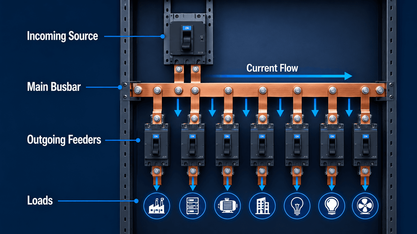
A busbar creates one electrically common node so an incoming source can feed several outgoing circuits with a compact, low-resistance conductor arrangement. In a switchgear lineup, for example, the incoming breaker energizes the main bus and feeder breakers tap power from that bus to downstream loads.
| Function | What the busbar must provide | Design consequence |
|---|---|---|
| Carry load current | Low-resistance path with acceptable temperature rise | Material, cross-section, spacing, ventilation, ambient temperature |
| Distribute current | Reliable taps and feeder connections | Hole pattern, joints, lugs, plated surfaces, mechanical access |
| Survive faults | Thermal and mechanical short-circuit withstand | Support spacing, bracing, insulators, conductor geometry, assembly rating |
| Maintain insulation | Adequate phase-to-phase and phase-to-ground separation | Clearance, creepage, barriers, insulation sleeves, enclosure geometry |
| Remain maintainable | Inspectible joints and safe isolation boundaries | Thermography access, covers, labels, bolted connection access |
Swipe horizontally to view all table columns.
A busbar is not just a piece of copper or aluminum. It is part conductor, part heat source, part mechanical structure, and part of the equipment’s protection and insulation system.
Types of Busbars
Busbars are built in several forms because low-frequency switchgear, high-frequency power electronics, flexible connections, and long busway runs have different electrical and mechanical needs.
| Busbar type | Typical application | Main advantage | Main design concern |
|---|---|---|---|
| Rigid flat busbar | Switchgear, switchboards, panelboards, substations | Compact, strong, easy to tap and support | Thermal rise, spacing, supports, joints and fault forces |
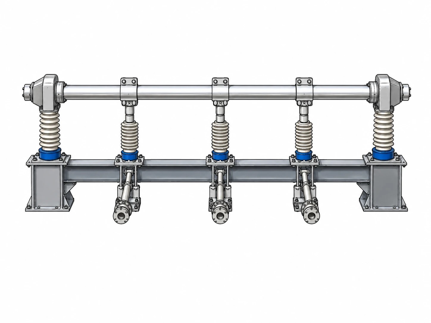
| Tubular / hollow bus | Outdoor substations and high-current/high-voltage bus systems | Good stiffness-to-weight and surface area | Structural supports, corona/electric field, wind and fault forces |
| Laminated busbar | Inverters, converters, EV power electronics, UPS systems | Low stray inductance and compact packaging | Layer insulation, thermal spreading, manufacturing tolerances |
| Flexible busbar | Battery racks, vibration-prone equipment, movable connections | Accommodates movement and alignment tolerance | Bend radius, termination pressure, insulation and current density |
| Busway / bus duct | Buildings, factories, data centers, industrial power distribution | Modular high-current routing with tap-off points | Joint assembly, environmental rating, voltage drop, thermal expansion |
| Outdoor substation bus | AIS switchyards and substations | Connects breakers, disconnects, transformers and lines | Clearance, support insulators, structural loading, fault forces |
Swipe horizontally to view all table columns.
Where Busbars Are Used
Busbars appear anywhere a design needs a compact high-current node, repeated feeder taps, or a rigid connection between power equipment sections.
| Application | Busbar role | High-value review item |
|---|---|---|
| Switchgear | Main, tie and feeder bus connects breakers | Continuous current, withstand current, insulation, arc-flash exposure |
| Switchboards / panelboards | Distributes source current to branch devices | Equipment listing, bus rating, breaker compatibility, neutral/ground arrangement |
| Substations | Connects lines, transformers, breakers and disconnects | Bus arrangement, BIL, clearances, short-circuit forces and structural support |
| Busway | Routes high current through buildings and plants | Joint resistance, tap-off units, voltage drop, enclosure/environmental rating |
| Battery / BESS systems | Combines parallel strings and distributes DC current | Fault energy, polarity spacing, DC arc risk, connection torque |
| Power electronics | Connects semiconductor stages, capacitors and DC links | Parasitic inductance, switching current, thermal path and laminated construction |
Swipe horizontally to view all table columns.
For the complete enclosure context, see Switchgear. For outdoor station arrangements, see Substations.
Busbar vs. Cable
Both busbars and cables carry current, but busbars are usually better for compact, rigid, high-current distribution inside equipment, while cables are usually better for flexible routing over distance.
| Decision | Busbar | Cable |
|---|---|---|
| High current inside equipment | Compact and mechanically organized | May require several parallel runs |
| Long irregular route | Less flexible unless using busway | Easy to route through trays, conduit or duct |
| Multiple taps | Efficient common node for many connections | Requires more individual terminations |
| High-frequency switching | Laminated bus can minimize stray inductance | Cable inductance can be harder to control in compact DC-link layouts |
| Field modification | Often equipment/manufacturer specific | Usually easier to reroute or replace |
| Fault forces | Rigid conductor/support system must withstand electrodynamic stress | Cable cleats and supports must control fault movement |
Swipe horizontally to view all table columns.
Busbar Sizing and Current Rating
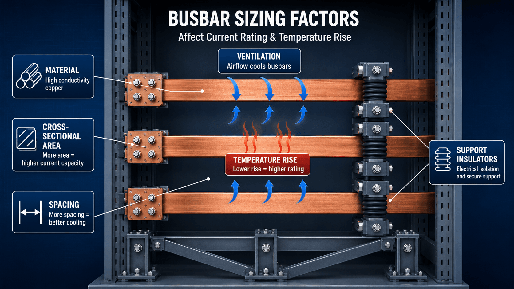
Busbar sizing starts with current but ends with temperature rise. The current creates \(I^2R\) loss, and the final operating temperature depends on conductor geometry, material, surface emissivity, ambient temperature, orientation, spacing, enclosure ventilation, and nearby heat sources.
Resistive Loss
Busbar Resistance
- \(I\)Current carried by the busbar.
- \(R\)Electrical resistance of the bar and current path.
- \(\rho\)Electrical resistivity of the conductor material.
- \(L\)Conductor length.
- \(A\)Cross-sectional area.
Current Density Is a Starting Point, Not a Final Rating
Designers sometimes use current density in A/mm² or A/in² as a rough first-pass sizing tool. That can be useful for early geometry, but there is no universal safe current-density value that replaces thermal verification. Enclosure conditions, temperature-rise limit, conductor arrangement, AC effects, material, and equipment standard can change the allowable current substantially.
Public ampacity tables are useful only when their assumptions match the design. The Copper Development Association, for example, publishes copper busbar ampacity data with defined emissivity and test assumptions; the final equipment design still needs verification against the actual enclosure and assembly rating.
Copper vs. Aluminum Busbars
Copper generally allows a smaller section for the same resistance, while aluminum reduces weight and can reduce material cost. The better choice depends on the entire equipment design rather than conductivity alone.
| Factor | Copper | Aluminum |
|---|---|---|
| Conductivity | Higher | Lower, so more cross-sectional area is commonly needed |
| Weight | Heavier | Much lighter |
| Equipment footprint | Can be more compact | May require larger dimensions or multiple bars |
| Joint behavior | Well-established copper/plated joint practice | Requires careful oxide control, compatible hardware and joint design |
| Thermal expansion | Lower than aluminum | Higher expansion must be considered at joints/supports |
| Material economics | Often higher material cost | Often lower material cost but not necessarily lower installed cost |
Swipe horizontally to view all table columns.
Short-Circuit Forces, Bus Bracing, and SCCR
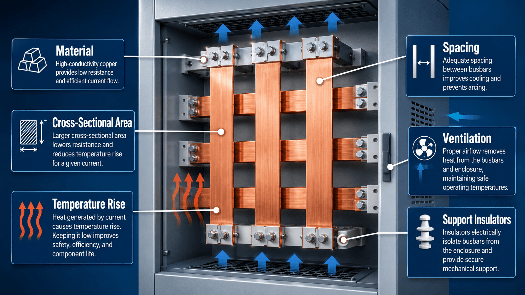
A busbar can be thermally adequate in normal service and still fail violently during a short circuit. High fault current produces large magnetic forces between parallel phase conductors, creating bending and support loads that rise rapidly with current.
Why the Complete Assembly Rating Matters
Short-circuit current rating (SCCR) and withstand performance depend on the complete assembly, not the bar alone. Conductor geometry, support spacing, insulators, joints, enclosure construction, breakers/fuses, and clearing time all influence whether the equipment can survive the fault.
Bus Ratings Inside Switchgear
Current IEEE switchgear standards specify preferred main-bus continuous current ratings and include requirements for temperature limitations, dielectric withstand, tests, and short-circuit performance. As of 2026, IEEE C37.20.1-2026 is the current standard for metal-enclosed low-voltage power circuit breaker switchgear, while IEEE C37.20.2-2025 covers metal-clad switchgear.
For system-level fault calculations, see Short Circuit Analysis.
Busbar Joints, Contact Resistance, and Overheating
Bus joints are frequently more failure-prone than straight sections of bar. A small increase in contact resistance can create a concentrated hot spot even when the rest of the busbar is operating normally.
| Cause | What happens | What to inspect |
|---|---|---|
| Loose bolted joint | Contact resistance rises and creates localized heat | Torque procedure, hardware, flatness, pressure and thermal image |
| Oxidation / corrosion | Degrades electrical contact surface | Plating, joint compound, compatible metals, environmental sealing |
| Overload | Whole conductor runs hotter than intended | Actual current, harmonics, ambient temperature, ventilation |
| Poor ventilation | Heat cannot escape the enclosure | Fans, filters, louvers, blocked airflow, enclosure temperature |
| Unequal parallel paths | One bar or branch carries more current | Geometry, joint resistance, connection symmetry |
| Harmonic current | Raises RMS current and AC losses | Current spectrum, neutral loading, skin/proximity effect |
Swipe horizontally to view all table columns.
Why Thermography Is So Useful
Infrared inspection under meaningful load can reveal bus joints, breaker stabs, taps, cable lugs, and phase connections operating hotter than similar neighboring connections. A temperature anomaly is a symptom—not a diagnosis—but it is often one of the fastest ways to find developing connection problems.
Neutral Busbar vs. Ground Busbar
A neutral bus carries normal grounded-conductor current. A ground bus bonds equipment grounding conductors and metal enclosures so fault current can return to the source and operate protective devices.
| Feature | Neutral bus | Ground bus |
|---|---|---|
| Normal current | May carry load current | Should not normally carry load current |
| Purpose | Grounded circuit conductor return point | Equipment bonding and fault-current path |
| Bonding | Bonded to ground only at required system bonding point(s) | Bonded to equipment enclosures and grounding conductors |
| Improper connection risk | Parallel neutral current on metal/grounding paths | Unsafe fault-clearing or objectionable current if misused |
Swipe horizontally to view all table columns.
Whether neutral and ground are bonded at a specific piece of equipment depends on whether it is service equipment, a separately derived system, or downstream distribution equipment. Follow the applicable code, equipment instructions, and system grounding design.
Busbar Engineering Review Checklist
A complete busbar review should move from normal load to abnormal duty, then to joints, insulation, maintenance, and the complete equipment rating.
| Review item | Verify | Risk if missed |
|---|---|---|
| Continuous current | Normal, peak and future loading | Thermal overload and accelerated aging |
| Temperature-rise basis | Ambient, enclosure, ventilation, insulation limits | Table rating does not match actual installation |
| Material / geometry | Copper/aluminum, bar width/thickness, parallel bars | Excess resistance, poor space use or difficult joints |
| Short-circuit duty | Available fault current, clearing time, assembly SCCR/withstand | Mechanical or thermal damage during fault |
| Supports / spacing | Insulators, unsupported span, phase spacing, enclosure clearance | Bus movement, flashover or structural failure |
| Joints | Surface condition, torque, plating, compatible metals | Hot joints and long-term reliability problems |
| Neutral / ground | Correct bonding and separation for system location | Objectionable current or poor fault-clearing path |
| Protection zone | Breaker, fuse, CT and relay boundaries | Fault not isolated as intended |
| Maintenance access | Safe isolation, covers, labels, thermal-inspection access | Developing problems remain hidden |
| Assembly standard | Manufacturer rating / listing / applicable IEEE, UL or IEC standard | Standalone conductor calculation conflicts with tested equipment design |
Swipe horizontally to view all table columns.
Busbar Engineering References
- Copper Development Association — Copper Busbar Application Data Provides practical copper busbar ampacity, mechanical-property, size-selection, emissivity, and AC skin-effect reference data. Ratings must be used with the stated assumptions.
- IEEE C37.20.1-2026 — Metal-Enclosed Low-Voltage Power Circuit Breaker Switchgear Current standard covering service conditions, ratings, main-bus continuous-current values, temperature limitations, dielectric withstand, testing, and application for low-voltage power switchgear.
- IEEE C37.20.2-2025 — Metal-Clad Switchgear Current IEEE standard for metal-clad switchgear, where the main bus and branch bus are key rated parts of the complete assembly.
Frequently Asked Questions
What is a busbar in electrical engineering?
A busbar is a low-impedance conductor used to collect and distribute current inside electrical equipment such as switchgear, switchboards, panelboards, substations, busway, battery systems, and power electronics.
Why are busbars usually made of copper or aluminum?
Copper and aluminum combine good electrical conductivity with practical mechanical and manufacturing properties. Copper is more conductive and compact; aluminum is lighter and often less expensive but usually requires more cross-sectional area.
How is busbar current rating determined?
Current rating depends on material, bar dimensions, temperature-rise limit, ambient temperature, spacing, orientation, surface condition, ventilation, enclosure conditions, and the applicable equipment or reference standard.
Why use a busbar instead of cable?
Busbars are useful for compact, rigid, high-current distribution with multiple taps and organized phase geometry. Cables are generally better for long or flexible routing.
What causes a busbar to overheat?
Common causes include overload, loose joints, excessive contact resistance, corrosion, poor ventilation, undersized conductors, harmonic current, unequal current sharing, and high ambient temperature.
What is busbar SCCR?
Short-circuit current rating describes the fault-current level an equipment assembly can withstand under its specified conditions. It is an assembly rating involving the bus, supports, enclosure, protective devices, and tested configuration—not just the busbar cross-section.
What is the difference between a neutral bus and a ground bus?
A neutral bus may carry normal return current. A ground bus bonds equipment grounding conductors and metal enclosures to provide a low-impedance fault-current path. Their bonding depends on the system location and grounding configuration.
What is a laminated busbar?
A laminated busbar stacks insulated conductor layers to create a compact high-current interconnect with low stray inductance. It is common in inverters, converters, UPS systems, EV power electronics, and DC-link applications.
How are busbars inspected?
Common checks include visual inspection, joint torque/condition review when permitted, thermography under load, insulation condition, discoloration, corrosion, support condition, and comparison of similar phase temperatures.
Summary and Next Step
Busbars are the current-distribution backbone inside many electrical assemblies. Their job is simple—carry and distribute current—but their engineering is not. Ampacity, temperature rise, joints, supports, insulation, spacing, short-circuit forces, material choice, and the complete equipment rating all affect whether a bus system is reliable.
The strongest design habit is to stop treating busbar size as the final answer. First verify normal thermal duty, then verify the joint and enclosure environment, then check fault withstand and mechanical support, and finally confirm that the complete switchgear, switchboard, busway, panel, or substation assembly is rated for the real system.