Key Takeaways
- Core idea: An inductor stores energy in a magnetic field and resists sudden changes in current.
- Engineering use: Inductors are used for filtering, ripple-current smoothing, energy transfer, reactors, chokes, EMI control, and power-quality applications.
- What controls it: Inductance, current, frequency, core material, saturation current, winding resistance, Q factor, self-resonance, and thermal limits control real behavior.
- Practical check: A real inductor is not pure \( L \); DCR, heat, core loss, saturation, and parasitic capacitance must be reviewed before use.
Table of Contents
Introduction
An inductor is a passive electrical component that stores energy in a magnetic field and opposes sudden changes in current. In power systems, electronics, and converter design, inductors appear as coils, chokes, reactors, filters, and energy-storage elements that shape current behavior, reduce ripple, limit transients, and support stable operation.
How Inductors Work Visually
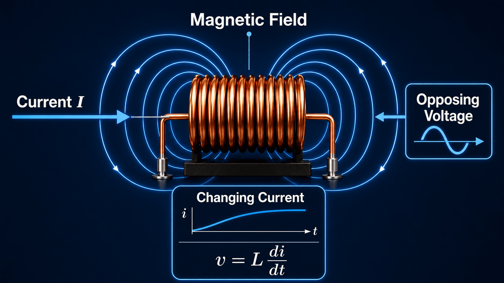
Read the image from left to right: current enters the coil, the coil builds a magnetic field, and a changing current creates voltage across the inductor according to \( v = L \frac{di}{dt} \).
What Is an Inductor?
An inductor is an electrical component designed to provide inductance, usually by winding conductive wire into a coil. When current flows through the winding, it creates a magnetic field. When that current changes, the magnetic field changes, and the inductor develops a voltage that opposes the change in current.
The key property is inductance, represented by \( L \) and measured in henries \( H \). A larger inductance value means the component produces more opposing voltage for a given rate of current change. In practical power work, inductors may be called chokes, line reactors, current-limiting reactors, or power inductors depending on their scale and application.
An inductor does not simply “block AC” or “pass DC.” More accurately, it opposes changes in current. At steady DC, an ideal inductor behaves like a short circuit; during changing current, switching, or AC operation, its inductance becomes important.
Inductor Symbol, Unit, and Circuit Meaning
Inductors are usually shown in circuit diagrams with a coil-shaped symbol. The circuit symbol represents the ideal inductance \( L \), but the physical component also has winding resistance, insulation limits, core behavior, and parasitic effects.
| Item | Meaning | Practical note |
|---|---|---|
| \(L\) | Inductance | Higher \(L\) produces more opposing voltage for the same rate of current change. |
| Henry, \(H\) | Base unit of inductance | Many practical components use smaller units such as mH, µH, and nH. |
| Coil symbol | Inductor in circuit diagrams | The symbol often hides real effects such as DCR, saturation, heat, and parasitic capacitance. |
| Choke | Inductor used to oppose unwanted AC, ripple, or noise current | Common in EMI filtering, power supplies, and cable noise control. |
| Reactor | Power-system-scale inductor | Used for line impedance, current limiting, harmonic filtering, or drive input protection. |
The most common misunderstanding is reading the schematic symbol as a perfect component. The symbol shows the intended inductive function, but engineering selection depends on how the real winding and magnetic core behave at the required current, frequency, and temperature.
How an Inductor Stores Energy in a Magnetic Field
Current through a wire produces a magnetic field. Winding the wire into a coil concentrates that field, so the component can store more magnetic energy for a given current. When the current increases, energy is transferred into the magnetic field. When the current decreases, the stored magnetic energy is returned to the circuit.
The current-change rule
The current through an ideal inductor cannot change instantaneously. In ideal analysis, inductor voltage rises according to the rate of current change. In real equipment, insulation limits, switch ratings, parasitic capacitance, arcing, clamps, and protection devices limit what actually happens during a fast transient.
Why coil geometry and core material matter
Inductance depends on winding turns, magnetic path, core material, air gap, and geometry. A ferrite or iron core can greatly increase inductance compared with an air-core coil, but it also introduces saturation and core-loss limits. In power applications, the core is not just a packaging detail; it strongly controls current rating, ripple behavior, heat, size, and efficiency.
Mutual inductance and coupled coils
When the magnetic field from one coil links another coil, changing current in the first coil can induce voltage in the second. This is called mutual inductance. It is the physical idea behind coupled inductors, transformer action, current transformers, and many magnetic power components.
Inductor Behavior in DC, AC, and Switching Circuits
Inductor behavior depends on the time pattern of current. The same component can act like a current-smoothing element in a converter, a reactance in an AC circuit, or a transient-limiting element during switching. That is why a single textbook description is not enough for engineering use.
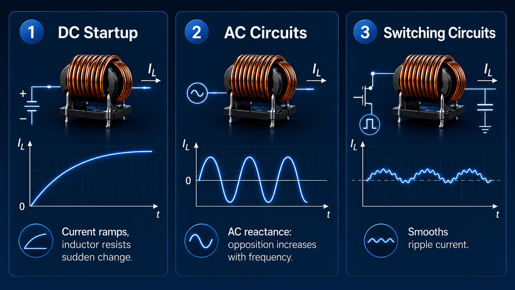
DC startup
When DC voltage is first applied to an inductor, current rises gradually instead of jumping to its final value. In a simple RL circuit, the winding resistance and external resistance eventually limit the steady-state current. At steady DC, an ideal inductor has no voltage drop, but a real inductor still has copper resistance and heat loss.
AC circuits
In sinusoidal AC operation, an inductor has reactance. Inductive reactance increases with frequency, so the same inductor opposes high-frequency current more strongly than low-frequency current. This is the reason inductors are useful in filters, chokes, harmonic control, and impedance-shaping applications.
Switching circuits
In switching converters, an inductor often stores energy during one part of the switching cycle and releases it during another. The goal is usually not to eliminate current ripple completely, but to keep ripple within a controlled range while meeting efficiency, size, thermal, and transient-response requirements.
Key Inductor Equations Engineers Use
Inductor equations are most useful when they are tied to physical behavior. The voltage equation explains why rapid current changes require large voltage. The energy equation explains magnetic energy storage. The reactance equation explains how inductors behave in AC circuits.
This voltage-current relationship says the voltage across an inductor is proportional to inductance and the rate of change of current. Fast current changes, high inductance, or both create higher voltage.
This equation gives the magnetic energy stored in an ideal inductor. The energy increases with inductance and with the square of current, which is why peak current is so important in power inductors and reactors.
Inductive reactance \( X_L \) increases with frequency \( f \). At higher frequency, the same inductance provides more opposition to sinusoidal current.
- \(L\) Inductance, measured in henries \(H\). Practical components often use mH, µH, or nH.
- \(i\) Instantaneous current through the inductor, usually measured in amperes.
- \(di/dt\) Rate of current change. This controls induced voltage during transients and switching.
- \(X_L\) Inductive reactance in ohms for sinusoidal AC analysis.
Inductor vs Capacitor vs Resistor
Inductors are easier to understand when compared with the other basic passive components. Resistors dissipate energy, capacitors store energy in an electric field, and inductors store energy in a magnetic field.
| Component | Stores energy in | Resists change in | Main equation idea | Common engineering use |
|---|---|---|---|---|
| Inductor | Magnetic field | Current | \(v = L \frac{di}{dt}\) | Filtering, current smoothing, reactors, chokes, converters, and energy transfer. |
| Capacitor | Electric field | Voltage | \(i = C \frac{dv}{dt}\) | Voltage smoothing, power factor support, filtering, coupling, and energy storage. |
| Resistor | Does not store ideal reactive energy | Current by dissipation | \(v = iR\) | Current limiting, voltage drop, damping, heating, sensing, and load modeling. |
A useful mental model is that capacitors dislike sudden voltage changes, inductors dislike sudden current changes, and resistors convert electrical energy into heat according to current and resistance.
Common Applications of Inductors
Inductors appear across electronics, power conversion, and power systems because many circuits need controlled current change. The physical size and construction may vary dramatically, but the magnetic-field principle remains the same.
| Application | What the inductor does | Example |
|---|---|---|
| Power supply filtering | Smooths current ripple and works with capacitors to reduce output variation. | Output filter in a DC power supply. |
| Switching converter | Stores and releases energy during switching cycles. | Buck converter, boost converter, or inverter stage. |
| EMI choke | Opposes unwanted high-frequency noise current. | Common-mode choke or ferrite choke on a cable. |
| Line reactor | Adds series impedance and limits rapid current change. | Input reactor for a variable frequency drive. |
| Harmonic filter | Works with capacitors to shape frequency response. | Tuned filter bank in a power-quality application. |
| Resonant circuit | Works with capacitance at a selected frequency. | LC filter or tuned circuit. |
Where Inductors Show Up in Power Systems
In power systems, inductors are often larger and may be described by their function rather than by the word “inductor.” A line reactor, current-limiting reactor, harmonic filter reactor, or choke still relies on the same magnetic-field behavior: it adds inductive impedance and resists rapid current change.
- Line reactors: Added in series with feeders, drives, or equipment to limit current change, reduce inrush stress, and improve drive-input behavior.
- Current-limiting reactors: Used in some systems to reduce available fault current and protect downstream equipment ratings.
- Filter reactors: Paired with capacitors or other components to tune harmonic filters or shape frequency response.
- DC-link and converter inductors: Used in rectifiers, inverters, renewable-energy converters, and power supplies to smooth current and control ripple.
- EMI and noise chokes: Used to oppose unwanted high-frequency current while allowing useful power flow.
In a one-line diagram, a reactor symbol may look simple, but the actual equipment decision includes insulation level, continuous current, short-time current, thermal rise, impedance, audible noise, enclosure, cooling, and fault-duty requirements.
Types of Inductors and What They Are Best For
Different inductor types exist because no single magnetic structure is best for every current, frequency, size, cost, and loss requirement. The right choice depends on whether the design is focused on power conversion, filtering, energy storage, signal behavior, or utility-scale impedance.
| Inductor type | Why it matters | Where it is commonly used | Engineering implication |
|---|---|---|---|
| Air-core inductor | No magnetic core saturation, but lower inductance for the same size. | RF circuits, high-frequency applications, and specialized filters. | Useful where core nonlinearity is unacceptable, but may be physically larger. |
| Ferrite-core inductor | Provides high permeability and compact inductance at many power-electronics frequencies. | DC/DC converters, EMI filters, and compact power supplies. | Core selection affects saturation, core loss, temperature rise, and EMI performance. |
| Iron-core or laminated reactor | Common in lower-frequency power and reactor applications. | Line reactors, utility reactors, motor-drive systems, and power equipment. | Often used where current and power levels are high, but core loss, noise, and heating require attention. |
| Toroidal inductor | Has an efficient closed magnetic path and can reduce stray field. | Power supplies, audio equipment, filters, and compact magnetic assemblies. | Often compact and efficient, but winding, isolation, and thermal design still matter. |
| Shielded power inductor | Controls stray magnetic field around the component. | Dense circuit boards, converters, and electronics near sensitive traces. | Useful near sensitive circuits, but shielding does not remove saturation or thermal limits. |
| Common-mode choke | Opposes noise currents that flow in the same direction on multiple conductors. | EMI filters, power cords, communications lines, and drive systems. | Useful for noise suppression, but it must be selected for current, frequency band, and insulation requirements. |
| Line reactor or choke | Applies inductance at equipment or power-system scale. | Variable frequency drives, feeders, rectifier inputs, and harmonic mitigation systems. | Selected by current rating, impedance, voltage class, loss, enclosure, and system duty. |
Ideal vs Real Inductors
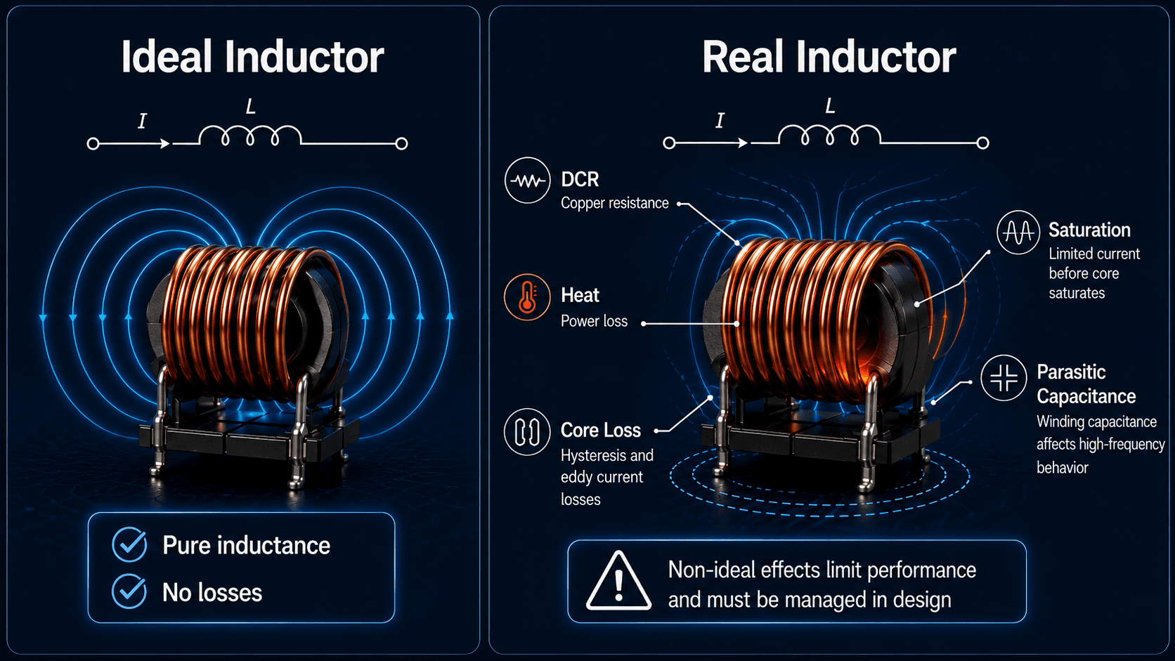
Ideal circuit theory treats an inductor as pure inductance. Real inductors include winding resistance, magnetic-core behavior, insulation limits, parasitic capacitance, heat rise, and frequency-dependent losses. Those details often control whether a design works reliably.
| Real-world effect | What it changes | Practical design concern |
|---|---|---|
| DC resistance, or DCR | Creates \( I^2R \) loss and voltage drop. | Raises temperature and reduces efficiency, especially at high RMS current. |
| Saturation current | Effective inductance drops when the core saturates. | Peak current must stay below saturation limits with appropriate margin. |
| Core loss | Magnetic material dissipates energy as frequency and flux swing increase. | Important in switching converters, filters, and reactors exposed to harmonics. |
| Parasitic capacitance | Windings act partly like a capacitor at high frequency. | Can reduce filtering effectiveness or create self-resonance. |
| Temperature rise | Changes resistance, insulation stress, and reliability. | Thermal environment, airflow, mounting, and enclosure conditions must be checked. |
Q factor and self-resonant frequency
Q factor describes how large the inductive reactance is compared with losses at a given frequency. A high-Q inductor has lower relative losses in resonant or filtering applications. Self-resonant frequency is the point where parasitic winding capacitance interacts with inductance enough that the component no longer behaves like a simple inductor.
Above self-resonance, an inductor can start behaving partly capacitive. This matters in EMI filters, RF circuits, switching power supplies, and any design where high-frequency noise or fast switching edges are present.
Senior Engineer Checklist for Selecting an Inductor
A useful inductor selection process starts with the required circuit function, then checks electrical, magnetic, thermal, mechanical, and operating-condition limits. The goal is not to choose the largest inductance value; it is to choose a component that behaves correctly under the actual current waveform and environment.
Define the function first: energy storage, ripple smoothing, AC reactance, harmonic filtering, EMI suppression, current limiting, or line impedance. Then check inductance, peak current, RMS current, saturation, DCR, core loss, frequency, thermal rise, and installation constraints together.
| Selection check | What to look for | Why it matters |
|---|---|---|
| Required inductance | Target \( L \) value at the operating current and tolerance range. | Sets ripple current, reactance, transient response, and filter behavior. |
| Peak current | Maximum instantaneous current, including startup, overload, and fault-related transients. | Peak current drives saturation risk and magnetic design margin. |
| RMS current | Heating current based on the actual waveform, not only average current. | RMS current determines copper loss and thermal rise. |
| DCR and efficiency | Winding resistance at expected temperature. | Higher DCR wastes power and creates voltage drop. |
| Operating frequency | Line frequency, switching frequency, harmonic content, or noise band of interest. | Frequency affects reactance, core loss, skin effect, Q factor, and parasitic behavior. |
| Core material and saturation | Ferrite, powdered iron, laminated steel, air core, or gapped magnetic structure. | Core material controls compactness, losses, current capability, and nonlinear behavior. |
| Self-resonant frequency | Frequency where parasitic capacitance changes the inductor’s behavior. | The inductor may stop behaving inductively above this frequency. |
| Thermal environment | Ambient temperature, enclosure, airflow, nearby hot components, and mounting. | A component that works on an open bench may overheat inside real equipment. |
How to read an inductor datasheet
Do not stop at the nominal inductance value. Review tolerance, rated current, saturation current, RMS or temperature-rise current, DCR, temperature rating, frequency range, core material, mechanical size, and test conditions. Datasheet ratings are only useful when compared with the actual waveform and environment in the design.
Worked Example: Energy Stored and AC Reactance
Assume a power inductor has \( L = 2 \text{ mH} \) and carries \( I = 8 \text{ A} \). The ideal magnetic energy stored at that current is:
The result means the inductor stores about 0.064 joules of magnetic energy at 8 A, assuming the inductance remains valid at that current. In real design, this result is only meaningful if the inductor has not saturated and its thermal rating is acceptable.
Same inductor in a 60 Hz AC circuit
At \( f = 60 \text{ Hz} \), the inductive reactance is:
At low frequency, this 2 mH inductor has modest reactance. At switching frequencies or harmonic frequencies, the reactance would be much higher. That frequency dependence is why the same inductance can be negligible in one application and dominant in another.
Engineering Judgment and Field Reality
Real inductor performance depends on waveform shape, installation, temperature, nearby magnetic materials, and the difference between datasheet test conditions and actual service conditions. A power inductor selected from a single nominal inductance value may fail the design if its saturation current, RMS current, or core-loss behavior is ignored.
In troubleshooting, heat, audible noise, unexpected voltage spikes, nuisance trips, distorted waveforms, or excessive ripple can point back to inductive behavior. The schematic may show a simple coil, but the field issue is often a combination of current waveform, core behavior, switching edges, and thermal environment.
When This Breaks Down
The simplified inductor model works well for basic circuit learning, but it breaks down when non-ideal effects become large compared with the intended inductive behavior. This is common in high-current, high-frequency, high-temperature, and transient-heavy applications.
- Core saturation: Effective inductance drops, so current can rise faster than expected.
- Thermal overload: Winding loss and core loss raise temperature beyond the component’s rating.
- High-frequency parasitics: Winding capacitance, skin effect, and self-resonance can make the inductor behave differently from the low-frequency model.
- Unexpected transients: Opening an inductive current path can create voltage spikes that stress insulation, switches, relays, or semiconductors.
- Application mismatch: A signal inductor, EMI choke, power inductor, and utility reactor are not interchangeable just because they all have inductance.
Common Mistakes and Practical Checks
Most inductor mistakes come from treating a real magnetic component like an ideal schematic symbol. The safest review approach is to check the current waveform, component rating, thermal condition, and system function together.
- Assuming bigger inductance is always better: Larger inductance may reduce ripple but increase size, cost, DCR, transient sluggishness, or saturation risk.
- Confusing rated current with saturation current: One rating may be thermal while another is magnetic; both matter.
- Ignoring RMS current: Average current can look acceptable while RMS heating current is too high.
- Forgetting switching voltage spikes: Inductors can generate large voltages when current paths are interrupted.
- Ignoring frequency: An inductor that works at line frequency may not behave correctly at switching, EMI, or self-resonant frequencies.
Do not choose an inductor from inductance value alone. Check the actual current waveform, saturation margin, RMS current, DCR, core loss, self-resonant frequency, temperature rise, and frequency range before calling the selection acceptable.
Useful References and Design Context
Inductors are governed by electromagnetic theory, but real applications also depend on datasheets, equipment standards, owner specifications, test methods, and safety requirements. For the underlying physics of inductance and magnetic energy, a strong educational reference is useful before moving into product-specific design.
- MIT electromagnetics reference: MIT material on inductance and magnetic energy explains the relationship between magnetic fields, inductance, and stored energy, which supports the core equations used in this article.
- Project-specific criteria: Power-system reactors, chokes, and converter inductors should also be checked against equipment specifications, insulation requirements, thermal limits, short-time current duty, and owner design standards.
- Engineering use: Engineers use references, datasheets, and test data to connect the ideal \( L \) value shown in analysis to the real magnetic component that must survive the operating environment.
Frequently Asked Questions
An inductor is a passive electrical component, usually made from a coil of wire, that stores energy in a magnetic field and resists sudden changes in current. In power systems and power electronics, that behavior is used for filtering, current smoothing, energy transfer, and current-limiting applications.
An inductor opposes changes in current. Depending on the circuit, it may smooth ripple current, filter noise, store and release energy in a switching converter, limit inrush or fault current, or work with capacitors to form filters and resonant circuits.
When current through an inductor changes, the magnetic field around the winding also changes. That changing magnetic field induces a voltage across the inductor that acts against the current change, which is why the current through an ideal inductor cannot jump instantly.
An inductor stores energy in a magnetic field and resists sudden changes in current. A capacitor stores energy in an electric field and resists sudden changes in voltage. The two components are often used together in filters, power supplies, and resonant circuits.
Inductor saturation occurs when the magnetic core can no longer support a proportional increase in magnetic flux as current rises. When saturation occurs, effective inductance drops, current can rise faster, heating can increase, and a power circuit may stop behaving as designed.
Summary and Next Steps
Inductors store energy in magnetic fields and resist changes in current. That simple idea explains why they appear in filters, reactors, chokes, switching converters, power supplies, current-limiting equipment, EMI controls, and power-quality applications.
The most useful engineering review goes beyond the ideal equation. Check inductance, current waveform, frequency, saturation, DCR, core loss, parasitic capacitance, self-resonance, and heat together. A real inductor must be selected for the actual system behavior, not just the value printed on a schematic.
Where to go next
Continue your learning path with related Turn2Engineering resources.
-
Power System Efficiency
Learn how losses, reactive power, equipment loading, and voltage level affect system-level energy performance.
-
Voltage Regulation
See how impedance, current, power factor, and equipment control affect delivered voltage in real systems.
-
Overcurrent Protection
Connect current behavior to protective devices, ratings, coordination, and fault protection.