
Direct Answer
The mechanical engineering design process is a structured, iterative method for turning a need into a part, assembly, machine, or system that satisfies defined requirements and constraints. The process typically progresses through requirements, concept development, engineering analysis, detailed design, manufacturing review, prototyping, verification, validation, iteration, and final design release.
It is not a rigid one-way sequence. Analysis, testing, manufacturing feedback, new information, or discovered failure modes can send a design back to an earlier stage until the evidence supports moving forward.
Key Takeaways
- Start with requirements: Define what the design must do, under what conditions, and how success will be measured before committing to geometry.
- Compare alternatives: Develop more than one viable concept so the first workable idea does not automatically become the final design.
- Design with evidence: Use calculations, simulation, manufacturing input, prototypes, inspection, and testing to challenge assumptions throughout development.
- Close the loop: Verification checks conformance to requirements; validation checks whether the finished solution performs its intended real-world job.
How to Use the Mechanical Engineering Design Process
A useful design process moves from an identified need toward increasingly detailed engineering evidence while allowing later discoveries to change earlier decisions.
A clearly defined need, measurable requirements, operating conditions, interfaces, constraints, and a way to determine whether the final design succeeds.
Concept generation, preliminary sizing, engineering analysis, detailed design, manufacturing review, prototyping, and requirement-based testing.
Verify that the realized product meets its requirements, validate that it solves the intended problem, resolve failures, and release a controlled design definition.
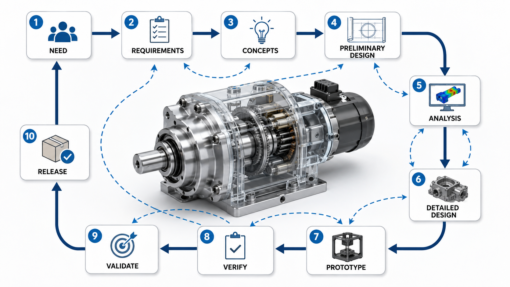
- Step 1 — Define the need: Identify the problem, opportunity, user need, or system function the design must address.
- Step 2 — Establish requirements: Translate the need into measurable functional, load, motion, environmental, interface, life, manufacturing, cost, safety, and schedule requirements where applicable.
- Step 3 — Generate concepts: Develop multiple ways to perform the required functions before committing to a detailed geometry.
- Step 4 — Select an architecture: Compare concepts against requirements, feasibility, risk, manufacturability, cost, size, reliability, and serviceability.
- Step 5 — Develop the preliminary design: Establish component arrangement, load paths, interfaces, material direction, packaging, and preliminary sizes.
- Step 6 — Analyze critical behavior: Use appropriate calculations, engineering models, simulation, supplier data, and physical reasoning to test the design assumptions.
- Step 7 — Complete detailed design: Resolve geometry, tolerances, fits, materials, fasteners, manufacturing details, assembly access, inspection requirements, drawings, and the bill of materials.
- Step 8 — Prototype and test: Build the minimum physical or representative setup needed to reduce important technical uncertainty.
- Step 9 — Verify: Collect evidence that the realized product conforms to the specified requirements.
- Step 10 — Validate and release: Confirm that the product fulfills its intended purpose, resolve remaining problems, and release the controlled final configuration.
Do not treat the numbered sequence as a waterfall. A project that allows the calendar to move forward but does not allow new evidence to change earlier decisions is following a schedule, not an effective engineering design process.
Where Are You in the Design Process?
The correct next design activity depends on what is currently uncertain: the requirements, the concept, the engineering behavior, or the evidence needed for release.
You do not need to treat every project as though it begins from zero. Identify the situation that best matches your current problem and begin there. If progress is blocked by an earlier assumption, work backward until the controlling issue is resolved.
Defining the problem
You know something needs to be created or improved but have not yet converted that need into measurable engineering requirements. Continue with requirements and constraints.
Selecting a concept
You understand the requirements but need to determine which architecture, mechanism, or physical approach deserves detailed development. Continue with concept development.
Analyzing a design
You have a promising layout or CAD model and need to determine whether the geometry, load paths, interfaces, and components are mechanically credible. Continue with preliminary design and analysis.
If the design is substantially defined and the question is whether it is mature enough for production or final approval, jump to the mechanical design review gate checklist.
Define Requirements and Constraints Before CAD
A mechanical design should begin with a clear definition of what the product must accomplish and the conditions that determine whether it succeeds.
A statement such as “make the bracket stronger” is not an adequate engineering requirement because it does not identify the controlling load, acceptable deformation, service life, operating environment, interfaces, or acceptance criteria.
Define the required function
Functional requirements state what the part, assembly, or machine must actually do. Depending on the application, a mechanical design may need to:
- Support or react a force, moment, torque, or pressure.
- Transmit torque, power, or motion.
- Constrain or permit movement.
- Locate one component relative to another.
- Maintain alignment or clearance.
- Seal pressure, fluid, contamination, or the environment.
- Dissipate, transfer, or isolate heat.
- Provide a controlled force, displacement, speed, or motion profile.
Identify the engineering inputs
Before geometry becomes detailed, collect the inputs that can materially change the design. The goal is not to document everything imaginable; it is to identify the conditions that can change size, material, architecture, interfaces, or acceptance criteria.
Loads and motion
Define forces, moments, torque, pressure, shock, vibration, speed, travel, acceleration, alignment, friction, and permitted degrees of freedom. These inputs usually establish the first load paths and sizing checks.
Environment and life
Temperature, corrosion, moisture, chemicals, contamination, UV exposure, duty cycle, fatigue exposure, wear, and maintenance intervals can change both material selection and the governing failure mode.
Interfaces and production
Capture mounting points, available envelope, neighboring equipment, assembly sequence, candidate processes, production quantity, supplier capability, inspection methods, cost, schedule, and applicable project constraints.
Requirements versus constraints
A requirement describes an outcome the solution must achieve. A constraint limits the solution space. Supporting an approved design load may be a requirement, while an existing bolt pattern, available envelope, or specified manufacturing process may constrain how that requirement can be met.
If the design team cannot explain what evidence would show that an important requirement passed or failed, the requirement may still be too vague.
ABET defines engineering design as a process of devising a system, component, or process to meet desired needs and specifications within constraints and describes engineering design as an iterative decision-making process involving analysis, evaluation, risk, tradeoffs, and multiple solutions: ABET Criteria for Accrediting Engineering Programs.
For broader guidance on the decisions that shape a mechanical design, see Mechanical Design Principles.
Generate and Compare Design Concepts
Concept development explores fundamentally different ways to satisfy the required functions before detailed geometry makes one approach expensive to abandon.
Break the problem into functions
Describe what the system must do without immediately describing what it looks like. A mechanism might need to support a load, locate a shaft, transmit torque, permit rotation, prevent translation, exclude contamination, and provide service access.
Once the functions are separated from the physical solution, alternative architectures become easier to generate.
Compare concepts using common criteria
The correct criteria depend on the project. A one-off prototype may prioritize development speed and flexibility, while a production product may place much more emphasis on unit cost, repeatability, assembly time, supplier capability, inspection, serviceability, and reliability.
| Criterion | Question to Ask | Useful Evidence | Common Failure |
|---|---|---|---|
| Functional performance | Can the concept perform every required function over the required operating range? | Calculations, layouts, simulations, mock-ups, tests. | The concept solves the primary function but fails an important secondary condition. |
| Technical feasibility | Can it realistically be designed, manufactured, assembled, and controlled? | Engineering analysis, supplier input, prototypes, process review. | The concept depends on unrealistic precision, unavailable technology, or unresolved interfaces. |
| Reliability and risk | What failure mechanisms or uncertainties does the concept introduce? | Failure-mode review, prior data, targeted testing. | Complexity introduces fatigue, wear, contamination, thermal, alignment, or maintenance risk. |
| Manufacturing and assembly | Can the design be produced and assembled repeatedly using appropriate processes? | Manufacturing review, supplier feedback, assembly study. | Tool access, inspection, distortion, process capability, or assembly sequence dominates cost. |
| Size and mass | Does the concept fit the available envelope and meet mass or inertia limits? | Packaging study, mass properties, clearance review. | A structurally sound design interferes with another system or creates unacceptable dynamic behavior. |
| Cost and schedule | What must be designed, sourced, manufactured, assembled, tested, and maintained? | Quotes, tooling estimates, labor estimates, lifecycle assumptions. | A low-cost component produces a higher-cost total system. |
| Serviceability | Can expected wear items be inspected, adjusted, lubricated, removed, or replaced? | Service simulation, access review, tool-clearance study. | Maintenance access is discovered only after physical assembly. |
Use the matrix as a decision aid
- Eliminate concepts that cannot meet mandatory requirements. A noncompliant concept should not win because it scores well on cost or simplicity.
- Weight meaningful differentiators. Do not assign large weights to criteria that every concept satisfies equally.
- Replace opinion with evidence. Use quick calculations, supplier information, mock-ups, tests, or known process capability where possible.
- Test decision sensitivity. If small scoring changes reverse the preferred concept, the alternatives may be too close for confident selection.
- Resolve the largest uncertainty. Run the fastest useful analysis or experiment that can distinguish the leading concepts.
If two concepts remain nearly tied, another meeting may add little value. Build the smallest calculation, mock-up, supplier study, or experiment that can resolve the uncertainty separating them.
Develop and Analyze the Preliminary Design
Preliminary design converts the selected concept into enough real geometry, component sizing, material direction, and interface definition to determine whether the architecture is mechanically credible.
Establish architecture, interfaces, and load paths
Identify where force, moment, torque, pressure, heat, or motion enters the system and how it travels to the supports or surrounding structure. A clear load path makes critical sections, joints, bearings, fasteners, and likely failure locations easier to identify.
Geometry must also respect the rest of the machine. Check envelope, movement, assembly access, maintenance access, component removal paths, neighboring structures, cables, hoses, and tolerance-sensitive interfaces.
Size critical components
Preliminary sizing may involve shafts, gears, bearings, fasteners, springs, couplings, frames, brackets, actuators, seals, or other machine elements. The controlling calculation depends on the component and application.
For structural components, use the Turn2Engineering Stress Analysis resource rather than treating one maximum-stress value as the complete design check.
Select materials for the actual environment
Material selection normally involves more than yield strength. Stiffness, fatigue, toughness, wear, corrosion, temperature, density, surface treatment, availability, joining, manufacturing route, inspection, and cost can all influence the correct choice.
See Material Selection for a deeper treatment of those tradeoffs.
Use analysis to challenge the design
Analysis should answer a specific engineering question. Depending on the system, useful checks may include reactions, stress, deformation, fatigue, stability, motion, torque, power, heat transfer, pressure, vibration, bearing loads, fastener loads, or contact behavior.
Higher-fidelity simulation can be valuable when the problem warrants it, but its result is only as credible as the loads, boundary conditions, material properties, contacts, mesh choices, assumptions, and interpretation behind the model.
Before trusting a detailed model, ask whether reaction forces balance the applied loads, deformation occurs in a physically reasonable direction, the predicted critical location is plausible, and the result is consistent with a simpler order-of-magnitude estimate.
Complete Detailed Design and Manufacturing Review
Detailed design converts a mechanically credible concept into a definition that can be manufactured, assembled, inspected, operated, maintained, and revised.
Resolve interfaces and final geometry
Review shoulders, fillets, ribs, transitions, hole locations, fastener access, bearing seats, locating features, alignment, sealing surfaces, service clearance, tool clearance, load introduction, and the paths needed to assemble and disassemble the product.
Control dimensional variation where function requires it
Manufactured dimensions vary. The objective is not to make every tolerance tight. The objective is to control dimensions and geometric relationships that materially affect fit, alignment, motion, sealing, interchangeability, inspection, or performance.
When form, orientation, location, runout, or datum relationships are important, the GD&T guide explains how geometric controls communicate the design intent.
When multiple dimensional variations accumulate through an assembly, use Tolerance Stack Up Analysis rather than assuming nominal CAD dimensions represent the worst case.
Review manufacturability before release
Manufacturing should influence the design before final release. Process selection affects geometry, material, tolerances, tooling, surface finish, joining, inspection, production rate, and cost.
A machined component has different practical constraints from a casting, welded fabrication, stamping, molded part, forging, or additive component. See Design for Manufacturing for a deeper review of these interactions.
Design for assembly, inspection, and service
A production-ready design must still work when a technician has to build, inspect, and later service it. Review the design from those three viewpoints instead of treating them as end-of-project details.
Assembly
Confirm realistic tool access, clear part orientation, reliable locating features, and an assembly sequence that does not depend on impossible reach or unnecessary adjustment.
Inspection
Make critical dimensions and geometric relationships practically measurable. A requirement that cannot be inspected economically may need a better datum scheme, feature definition, or verification method.
Service
Check removal paths, lubrication access, wear-item replacement, cleaning, and adjustment. Normal manufacturing variation should still allow the product to assemble and function without field rework.
For assembly-focused decisions such as part count, orientation, access, and assembly sequence, continue with Design for Assembly.
A design can pass every nominal CAD interference check and still fail on the shop floor because a tool cannot reach a fastener, a bearing cannot be installed without damage, a weld distorts an interface, or normal tolerance variation prevents assembly.
Prototype, Verify, and Validate the Design
Prototypes reduce uncertainty, verification checks conformance to specified requirements, and validation determines whether the resulting product fulfills its intended purpose.
Prototype to answer a question
A prototype does not need to duplicate the finished product in every detail. It needs to answer the engineering question for which it was built.
Different prototypes can evaluate packaging, motion, ergonomics, load capacity, stiffness, thermal behavior, assembly sequence, manufacturing feasibility, sealing, vibration, controls, or durability. A simple fixture or partial assembly may provide more useful evidence than a polished full prototype when it isolates the uncertainty that actually controls the decision.
For fast physical iteration techniques, see Rapid Prototyping.
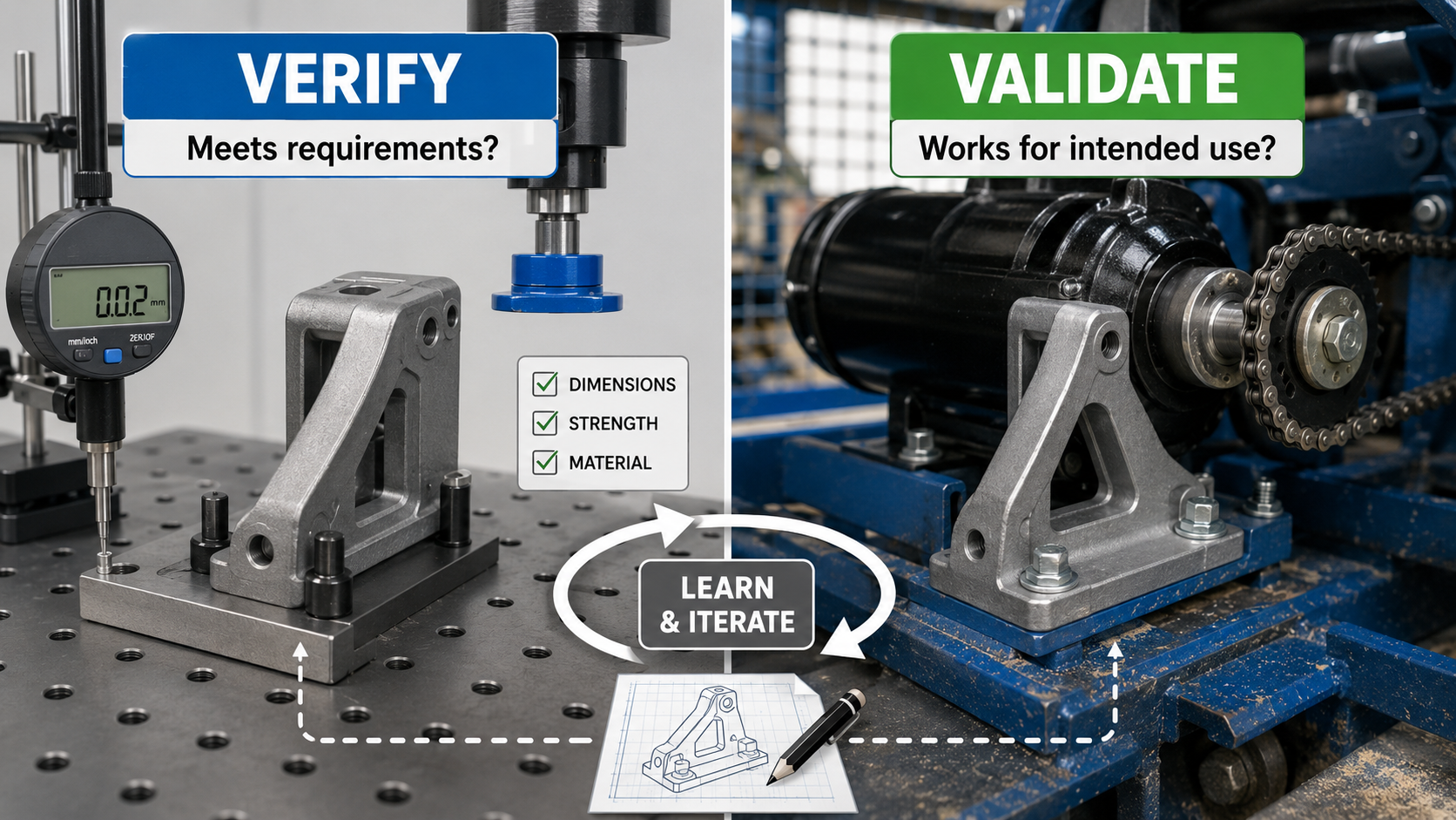
Verification: did the product meet its requirements?
Verification connects the realized product back to the requirements established during development. Depending on the requirement, suitable evidence may come from analysis, inspection, test, demonstration, or an appropriate combination.
| Requirement Type | Design Response | Possible Verification Method | Acceptance Question |
|---|---|---|---|
| Load capacity | Size load-carrying geometry, joints, and interfaces for the applicable load cases. | Analysis and/or physical load testing. | Does the design satisfy the approved load-related requirement and acceptance criteria? |
| Dimensional interface | Define geometry, datum relationships, dimensions, and tolerances. | Inspection. | Does the manufactured interface conform to the specified dimensional controls? |
| Motion or function | Define mechanism, clearance, travel, stops, drives, and controls as applicable. | Demonstration and/or test. | Does the realized system perform the specified function over the required range? |
| Environmental performance | Select suitable materials, finishes, seals, clearances, and components. | Analysis, inspection, environmental testing, or a suitable combination. | Does the product conform to its approved environmental requirements? |
The actual verification method and acceptance criteria must come from the project requirements. The examples above illustrate traceability rather than prescribing mandatory methods.
Validation: does the product solve the intended problem?
Validation asks the broader intended-use question. A product can conform to its documented requirements yet still reveal an incomplete requirement set when evaluated in realistic use.
If that occurs, the correct response may be to revisit assumptions, stakeholder needs, use cases, or requirements rather than merely modifying the final component.
NASA distinguishes product verification from product validation by connecting verification to conformance with requirements and validation to fulfillment of intended purpose in the intended environment: NASA — Distinctions Between Product Verification and Product Validation.
Mechanical Design Review Gate Checklist
Use design gates as evidence-based questions rather than calendar milestones. A design should advance because the information required for the next stage is mature enough and the remaining risk is understood.
Gate 1 — Requirements ready
Advance when: the need, intended function, major interfaces, operating conditions, and measurable requirements are understood well enough to compare concepts.
Hold when: the team still cannot explain what success means or how a critical requirement could eventually be verified.
Gate 2 — Concept ready
Advance when: meaningful alternatives have been compared, the selected architecture can satisfy the major requirements, and the dominant technical risks are visible.
Hold when: the preferred concept still depends on an assumption that could invalidate the architecture.
Gate 3 — Ready for prototype or production-intent testing
Advance when: load paths, critical sizing, materials, interfaces, manufacturability, and the purpose of the planned test are sufficiently defined.
Hold when: the test would generate data without resolving a specific design uncertainty or acceptance question.
Gate 4 — Release ready
Advance when: required verification and validation evidence is complete, unresolved failures are addressed, production and inspection requirements are documented, and the released files describe the same configuration.
Hold when: “CAD complete” is being used as a substitute for technical maturity, manufacturing readiness, or controlled evidence.
Do not release a design simply because drawings are finished. Release maturity depends on unresolved technical risk, verification status, validation needs, manufacturing definition, inspection capability, and configuration control.
Worked Design Process Example: Motor Mount Bracket
Consider a bracket used to locate and support an electric motor on a machine frame. The example shows how the design process changes the engineer’s questions as the design matures rather than prescribing real dimensions, materials, or safety factors.
1. Define what the bracket must accomplish
Start with the motor and frame interfaces, reaction loads and torque, drivetrain alignment, available envelope, vibration environment, duty cycle, service access, manufacturing constraints, and the evidence that will demonstrate acceptable performance.
2. Compare architectures before detailing one
A formed plate bracket, machined plate-and-rib design, and welded fabrication may all be plausible. Compare stiffness, load path, adjustment, manufacturing effort, distortion risk, production quantity, mass, cost, and service access before detailed CAD makes one option expensive to abandon.
3. Turn the selected concept into engineering evidence
Resolve the load path from the motor into the frame, then check bolt locations, section depth, local stress, joint behavior, stiffness, fatigue, alignment, vibration, manufacturing process, tolerances, hardware, and installation access. Prototype or test only where it reduces a meaningful uncertainty.
4. Verify the bracket in the machine, then release it
Confirm that the manufactured bracket meets its dimensional and performance requirements and that the installed motor behaves correctly in the intended machine. Only then should drawings, bill of materials, manufacturing information, inspection requirements, and revision state be released as one controlled configuration.
The bracket is not successful merely because calculated stress is acceptable. Alignment, stiffness, vibration, fatigue, joint behavior, manufacturing variation, installation access, and actual machine behavior may be equally important.
Common Mechanical Design Process Mistakes
Many mechanical design failures begin as process failures: an undefined requirement, unchecked assumption, poorly understood interface, or decision made before enough evidence exists.
Designing geometry before the problem is stable
Starting CAD too early makes the first shape feel like the solution. Requirements, interfaces, and concept alternatives should be mature enough that geometry is expressing a decision rather than hiding uncertainty.
Analyzing the wrong problem in great detail
Simulation can look authoritative while still using the wrong loads, boundary conditions, contact assumptions, or failure criterion. First explain the load path and likely governing behavior in plain engineering terms; then use higher-fidelity analysis where it can actually change the decision.
Treating strength as the entire design
A part may avoid yield and still fail because it deflects too much, loses alignment, fatigues, wears, vibrates, buckles, leaks, loosens, or cannot be assembled. The governing failure mode must come from the function and operating conditions, not from whichever calculation is easiest to run.
Inviting manufacturing and inspection too late
Tool access, process capability, distortion, supplier limitations, tolerance cost, and inspection difficulty can force major redesign late in the project. Reviewing those constraints while geometry is still flexible is usually cheaper than correcting them after drawings are nearly complete.
Testing without a decision rule
A test is not useful merely because data was collected. Define what is being verified, what constitutes a pass or failure, and which design decision changes based on the result. Keep the test configuration tied to the same revision as the CAD, drawings, analyses, and bill of materials.
When a design concern becomes a failure investigation, use the Turn2Engineering guide to Failure Modes to examine how mechanical components can lose function.
There is no single mandatory design-process sequence for every mechanical project. Product risk, industry requirements, applicable standards, company procedures, customer criteria, manufacturing route, and regulatory obligations can change both the process and the required documentation.
Design Process Engineering References
These sources support the engineering-design, iterative-development, verification, validation, and product-realization concepts used throughout this page.
- ABET — Criteria for Accrediting Engineering Programs, 2026–2027 Supports the definition of engineering design as an iterative process involving requirements, analysis, multiple solutions, evaluation, risk, constraints, and tradeoffs.
- NASA Systems Engineering Handbook — System Design Processes Supports the iterative relationship among stakeholder expectations, requirements development, alternatives, analysis, and design-solution development.
- NASA — Distinctions Between Product Verification and Product Validation Supports the distinction between demonstrating conformance to requirements and determining whether a product fulfills its intended purpose in its intended environment.
- ASME — Design Engineering Division Provides professional context for design engineering across product conception, evolution, manufacturing, and product realization.
Frequently Asked Questions
What are the steps in the mechanical engineering design process?
A practical sequence is to define the need, establish requirements and constraints, generate and select concepts, create a preliminary design, analyze critical features, complete detailed design, review manufacturing and assembly, prototype, verify requirements, validate intended use, iterate where necessary, and release the controlled final design.
What is the difference between engineering design and CAD?
CAD is a tool for creating and documenting geometry. Engineering design is the broader decision process that defines requirements, compares concepts, evaluates load paths and interfaces, performs analysis, selects materials and processes, controls tolerances, manages risk, supports manufacturing, and verifies and validates the finished product.
Does the engineering design process always follow the same order?
No. Real design work is iterative. Analysis can change geometry, prototype results can change assumptions or interfaces, manufacturing feedback can change detailed design, and validation can reveal that the original requirements did not fully capture the intended use.
What is the difference between verification and validation?
Verification determines whether the realized product conforms to its specified requirements. Validation determines whether that product fulfills its intended purpose in its intended environment. A design can therefore verify successfully yet still reveal a validation problem if the requirements did not fully represent the real use case.
When is a mechanical design ready for production?
A design is ready when the project’s release criteria have been satisfied: important requirements and interfaces are defined, necessary analyses and reviews are mature, required verification and validation evidence supports the design, manufacturing and inspection requirements are resolved, documentation is consistent, and remaining risks are understood and appropriately accepted.
Summary and Next Step
The mechanical engineering design process converts a need into a manufacturable and supportable product through requirements, concept development, engineering analysis, detailed design, prototyping, verification, validation, iteration, and controlled release.
The most important practical lesson is not to confuse completed geometry with completed engineering. A design becomes mature when its critical assumptions, requirements, interfaces, failure risks, manufacturing constraints, and intended use have been addressed with appropriate evidence.