Key Takeaways
- Definition: Deep foundations are structural elements that transfer load below weak near-surface soils into deeper, more reliable ground using shaft resistance, end bearing, or both.
- Use case: They are selected when shallow foundations cannot control settlement, uplift, lateral demand, scour risk, or overall reliability economically.
- Main decision: The real design question is not just “Can a pile carry the load?” but “Which deep foundation type best fits the ground, loads, access, vibration limits, and construction risk?”
- Outcome: After reading, you should understand selection logic, basic capacity concepts, practical field limitations, and the checks that matter before construction starts.
Table of Contents
Introduction
In brief: Deep foundations support structures by carrying load deeper into soil or rock when surface soils cannot safely or economically control strength, movement, or long-term performance.
Who it’s for: Students, FE/PE prep, and designers.
For informational purposes only. See Terms and Conditions.
This page explains what deep foundations are, why engineers use them, how they work, and where theory needs to be checked against field reality before a design is trusted.
Deep Foundations infographic
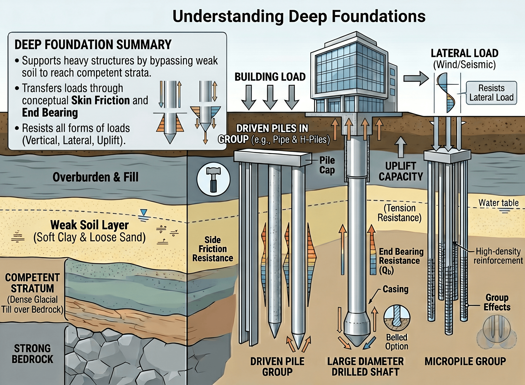
Notice the difference between weak near-surface soils and the deeper stratum the foundation is targeting. The core idea is that deep foundations are not defined only by depth; they are defined by how they bypass or mobilize soil layers to achieve reliable support.
What are deep foundations?
A deep foundation is a foundation system that transfers load well below the ground surface because the upper soils are not adequate, not reliable, or not economical to use for direct support. In practice, that usually means the engineer is trying to solve one or more controlling problems: weak fill, soft clay, high groundwater, large total settlement, differential settlement, uplift, lateral loading, scour, liquefaction risk, or severe access constraints.
The phrase includes several families of systems rather than one single element type. Common examples are driven piles, drilled shafts, micropiles, and auger-cast or continuous flight auger piles. Some systems are installed by driving, some by drilling and concreting in place, and some by high-capacity grouting. The engineering choice depends as much on constructability and risk as on theoretical capacity.
That is why deep foundations should be thought of as a decision category, not just a geometric description. A foundation does not become “good” because it is deeper. It becomes appropriate when the chosen element, installation method, and verification approach match the actual subsurface model and the performance criteria of the structure above.
If you are new to the subject, it helps to connect this page with broader topics such as What is Geotechnical Engineering, Foundation Design, and Pile Foundations. Deep foundations sit at the intersection of site investigation, structural loading, soil behavior, and construction quality.
How deep foundations carry load: core principles, variables, and units
Deep foundations carry load through one or more resistance mechanisms. The two most familiar are shaft resistance along the embedded length and end bearing at the tip. In reality, those mechanisms develop gradually with movement, and their relative share can change depending on soil type, installation method, stress history, drainage, and how the structure actually loads the element over time.
Key variables and typical ranges
Engineers usually start by separating axial compression, uplift, and lateral demand. A system that looks strong in pure axial compression may still be a poor choice if lateral stiffness, vibration limits, or nearby structure sensitivity control the design. Movement criteria are often just as important as ultimate capacity.
- \(Q\) Axial load on one element; often reported in kN or kips. This comes from structural load combinations, not from geotechnical judgment alone.
- \(Q_s\) Shaft resistance developed along the embedded length; commonly important in clay, sand, and rock sockets depending on strain level and installation effects.
- \(Q_b\) End bearing or toe resistance at the base; often critical when the tip reaches dense soil, hardpan, or rock.
- \(L\) Embedded length of the element; longer is not always better if settlement, buckling, cost, or installation tolerance becomes controlling.
- \(D\) Diameter or characteristic width; affects stiffness, side area, toe area, and constructability. Report in mm/in or m/ft.
- \(s\) Settlement or displacement; usually mm or in. This is often the number owners care about most because it drives cracking, distortion, and serviceability.
- \(H\) Lateral load; usually kN or kips. Critical for bridge piers, towers, retaining systems, marine structures, and signs.
Never treat “capacity” as the only target. Many deep foundation problems are movement-controlled, installation-controlled, or group-effect-controlled long before nominal ultimate resistance becomes the real limit.
A useful mental model is this: shallow foundations spread load through the near surface, while deep foundations concentrate load into discrete elements that interact with the ground along depth. That means load transfer is more sensitive to local layering, groundwater, installation disturbance, and construction records. A small mismatch between the assumed profile and the actual profile can matter much more than it would for a large mat or spread footing.
Selection workflow: when engineers choose deep foundations
Good deep foundation design starts with the controlling problem, not the preferred product. The engineer first asks whether a shallow system can work. If shallow foundations cannot satisfy bearing, settlement, differential movement, scour, uplift, or lateral requirements at acceptable cost and risk, then deep foundations move to the front of the decision process.
Start with the subsurface model and structural load path. If competent support exists near grade and movement is acceptable, keep shallow foundations on the table. If weak compressible soils, uncontrolled fill, aggressive groundwater, scour, liquefaction, or high lateral/uplift loads govern, evaluate deep systems. Then choose among driven piles, drilled shafts, micropiles, or other deep elements based on access, vibration tolerance, obstructions, target layer depth, production rate, and inspection/testing strategy.
This is where system selection becomes practical engineering rather than abstract theory. Driven piles can offer strong quality traceability and fast production, but vibration and noise can become unacceptable near sensitive structures. Drilled shafts can provide large capacities and strong lateral performance, but they demand tight control of excavation stability, groundwater management, cleanliness at the base, and concrete placement. Micropiles can work beautifully in restricted-access retrofits, yet they require careful attention to grout quality, casing details, and connection design.
In other words, the best deep foundation type is the one that solves the actual site problem with the lowest overall project risk—not the one with the biggest nominal capacity on paper.
Equations and calculations
At the concept level, the most useful axial capacity relationship is the idea that total resistance can come from both the shaft and the base. A simplified expression is:
Here, \(Q_{ult}\) is the ultimate axial compression resistance, \(Q_s\) is total shaft resistance, and \(Q_b\) is end bearing at the tip. That equation is simple, but using it well is not. The values are not just numbers from a chart. They depend on installation method, soil layering, groundwater, time effects, group interaction, and the movement required to mobilize each resistance component.
For preliminary thinking, engineers often estimate shaft resistance by summing unit side resistance over depth and estimate toe resistance from the area at the tip and an interpreted base pressure:
In those expressions, \(f_s\) is unit shaft resistance, \(A_s\) is side area over each layer, \(q_b\) is unit base resistance, and \(A_b\) is base area. For service design, however, the engineer also has to check displacement, stiffness, settlement compatibility with the superstructure, and group behavior. A pile that looks acceptable in ultimate compression may still overstress the cap, rotate too much under lateral load, or produce unacceptable differential settlement.
That is why deep foundation calculations are usually performed as a workflow:
- Define the load combinations and what really controls: compression, uplift, lateral, moment, or movement.
- Build a realistic soil and groundwater profile from the investigation.
- Select candidate foundation types and installation methods.
- Estimate axial and lateral performance using methods appropriate to the soil conditions and project risk.
- Check constructability, spacing, cap geometry, durability, and testing/acceptance requirements.
Worked example: concept-level check for a single deep foundation element
Example
Suppose a mid-rise structure is supported over soft near-surface clay underlain by dense sand at depth. A preliminary concept study shows that shallow foundations would lead to excessive settlement, so the team evaluates a single deep foundation element carrying a service load of 450 kN (about 100 kips). Based on interpreted parameters for the selected element and profile, the estimated ultimate shaft resistance is 500 kN and the estimated ultimate base resistance is 700 kN.
Using the simplified equation, the total ultimate resistance is:
If the project uses a concept-level factor of safety of 2.5 for preliminary screening, the rough allowable compression load becomes:
On that basis, the element appears adequate for axial compression because 480 kN exceeds the 450 kN service demand. But an experienced engineer does not stop there. The next questions are the ones that decide whether the concept survives:
- How much settlement is required to mobilize those shaft and base components?
- Will negative skin friction develop if surrounding fill or soft clay consolidates?
- Does the element also resist lateral load or overturning moment?
- Are spacing and cap stiffness going to reduce efficiency in a group?
- Can the contractor actually install and verify the element the way the design assumes?
This is the core lesson of deep foundations: passing a simple axial calculation is only the beginning. Real design becomes credible when axial, lateral, uplift, stiffness, construction tolerance, and verification are all aligned.
Engineering judgment and field reality
Deep foundation design is especially sensitive to what the investigation misses and what construction changes. The soil profile is never known perfectly. A borings program may identify the general stratigraphy but miss thin weak seams, cobbles, voids, debris, variable rock elevation, artesian water, or local fill differences. Those details can completely change installation behavior and sometimes matter more than the theoretical design model.
Installation method also changes the ground itself. Driven piles may densify some granular soils and disturb others. Drilled shafts can lose side resistance if the excavation loosens, sloughs, or traps soft sediments at the base. Micropiles depend heavily on grout quality, bond zone execution, and the actual behavior of the surrounding ground. So even before load testing, the field may already have changed the foundation the calculations were based on.
The installed foundation element is the real structure. Design assumptions, boring logs, and spreadsheet outputs matter only if inspection, construction records, and testing confirm that the installed system actually matches the intended performance model.
Another field reality is that deep foundations are often chosen because projects are already constrained. Downtown sites, bridge widenings, marine conditions, retrofits, tower foundations, and emergency repairs rarely offer perfect access or clean staging. Equipment size, headroom, spoil handling, vibration restrictions, and concrete delivery timing can control the final design as strongly as geotechnical resistance.
Where this method breaks down
Simplified deep foundation thinking breaks down when the profile is highly layered, when lateral or cyclic loading dominates, when group interaction becomes strong, or when time-dependent behavior matters. A neat single-element capacity estimate can become misleading if the real foundation works as a closely spaced group with settlement interaction and cap stiffness effects.
It also breaks down when the project is controlled by serviceability rather than strength. Tall structures, sensitive equipment foundations, bridge substructures, retaining systems, and marine works often fail functionally because of movement, not because the ultimate geotechnical resistance was too low. In such cases, stiffness modeling, p-y behavior, load testing, and construction tolerance become more important than a simple ultimate resistance calculation.
Other breakdown cases include:
- Downdrag or negative skin friction from consolidating fill or soft clay.
- Scour removing confining soil around piles near water crossings.
- Liquefaction reducing lateral support and changing bending demands.
- Obstructions or variable rock elevation causing installation deviation.
- Assuming a deep element reaches competent bearing when refusal, cleanliness, or socket quality is uncertain.
Whenever one of these conditions appears, the correct response is not to “add a little conservatism” blindly. It is to change the model, improve the investigation, revise the construction method, or increase verification through testing and inspection.
Common pitfalls and engineering checks
- Using ultimate capacity numbers without checking movement at service load.
- Ignoring the effect of installation method on actual resistance and stiffness.
- Assuming group capacity equals single-element capacity times the pile count.
- Overlooking downdrag, scour, liquefaction, or seasonal groundwater change.
- Failing to coordinate geotechnical assumptions with cap layout and structural detailing.
One of the most costly errors is designing a deep foundation for axial compression only, then discovering late in the project that lateral stiffness, uplift, or constructability was actually the governing requirement all along.
| Parameter | Symbol | Typical units | Why it matters |
|---|---|---|---|
| Axial compression load | \(Q\) | kN, kips | Starts the sizing check, but should never be the only design criterion. |
| Lateral load | \(H\) | kN, kips | Often governs pile bending, deflection, and required embedment. |
| Settlement / deflection | \(s\) | mm, in | Controls serviceability and often drives owner concerns. |
| Embedded length | \(L\) | m, ft | Affects load transfer, stiffness, and construction cost. |
| Spacing | \(S\) | m, ft, or diameters | Influences group interaction, cap geometry, and installation access. |
Before finalizing any deep foundation system, ask three blunt questions: What is the controlling performance limit, what field evidence will verify the design assumptions, and what site condition could make this concept fail even if the spreadsheet looks clean?
Visualizing the deep foundation decision
A helpful way to picture the selection process is as a three-layer filter. First, the engineer checks whether shallow support is possible. Second, the engineer identifies the controlling reason for going deep: weak soils, settlement, lateral demand, uplift, scour, or access. Third, the engineer compares candidate systems against construction constraints such as vibration, headroom, spoils, groundwater, and inspection needs.
That mental model keeps the design grounded in project reality. Deep foundations are rarely selected because one type is universally “best.” They are selected because one option fits the specific ground, structure, and construction environment better than the alternatives.
This is often easier to understand as a logic tree during design review meetings, especially when multiple stakeholders are balancing risk, cost, and schedule.
Relevant standards and design references
Deep foundation work is governed by project type, owner requirements, and the foundation family being used. These are the references most designers should recognize early:
- AASHTO LRFD Bridge Design Specifications: Core reference for transportation-related deep foundation design, especially where bridge loading, resistance factors, and serviceability criteria must be coordinated with geotechnical and structural checks.
- FHWA Structural Foundations guidance: Useful for selection, design, performance, QA/QC, construction monitoring, inspection, and testing across driven piles, micropiles, auger-cast piles, and drilled shafts.
- FHWA guidance for laterally loaded deep foundations: Particularly important when lateral loading, combined loading, bridge substructures, signs, walls, and seismic demands control the design instead of pure compression.
- FHWA Acceptance Procedures for Deep Foundations: Strong reference for what should be inspected, recorded, and verified for driven piles, drilled shafts, micropiles, and CFA piles during construction and acceptance.
- Project-specific geotechnical investigation, material, and testing standards: Site characterization, concrete/grout quality, steel properties, and load testing protocols still have to match the owner and foundation type used on the project.
Frequently asked questions
Shallow foundations transfer load into competent soils near the ground surface, while deep foundations carry load to deeper strata or develop resistance along the shaft when near-surface soils are too weak, compressible, or risky. The choice is usually controlled by settlement, groundwater, lateral demand, scour, access, and constructability—not depth alone.
Engineers typically move to deep foundations when shallow systems cannot meet bearing, settlement, uplift, or lateral requirements economically. They are also common where scour, liquefaction, expansive soils, fill, soft clay, or sensitive nearby structures make near-surface support unreliable.
No. Many deep foundations resist load through a combination of shaft resistance and end bearing. In some soils, shaft resistance may control; in others, tip resistance becomes dominant. The governing mechanism depends on soil profile, installation method, pile geometry, and movement level.
Common causes include poor subsurface characterization, ignoring installation effects, overlooking group interaction, underestimating downdrag or scour, and assuming axial capacity alone is enough. Many field problems come from movement, construction deviation, or changing site conditions rather than a simple lack of ultimate resistance.
Summary and next steps
Deep foundations are used when the ground near the surface cannot provide dependable support or when project demands make shallow systems too risky. Their performance depends on more than axial capacity. Settlement, stiffness, lateral response, installation effects, group behavior, and field verification all shape whether a design actually works.
The strongest deep foundation designs start with a clear understanding of what controls the project: weak soils, movement tolerance, groundwater, scour, uplift, lateral loading, access, or construction risk. From there, engineers compare system types, choose realistic analysis methods, and make sure the intended performance can be confirmed during construction.
If you remember one thing from this page, make it this: deep foundations are successful when the installed element matches the design assumptions. Good geotechnical judgment connects subsurface interpretation, foundation selection, structural demand, and construction evidence into one defensible workflow.
Where to go next
Continue your learning path with these curated next steps.
-
Read a deeper dive on Foundation Design
Useful for understanding how deep foundations fit within the broader process of selecting and proportioning the right support system.
-
Study Pile Foundations in more detail
The best next step if you want a more focused look at one major family of deep foundation systems.
-
Review Settlement Analysis
Helpful when serviceability, long-term movement, or differential settlement is what really controls your design.