Key Takeaways
- Core idea: Structural design creates a complete load-resisting system, not just isolated beams, columns, slabs, and foundations.
- Engineering use: Engineers use structural design to choose systems, determine loads, size members, detail connections, check serviceability, and coordinate construction documents.
- What controls it: Loads, span lengths, support conditions, material behavior, lateral resistance, deflection, drift, vibration, connection forces, and foundation reactions can all govern the design.
- Practical check: A design is not complete until gravity loads, lateral loads, member checks, connection details, and foundation support all form a continuous load path.
Table of Contents
Introduction
Structural design is the engineering process of selecting, analyzing, sizing, and detailing structural systems so a building, bridge, frame, wall, or other structure can safely resist loads and transfer them to the ground. It combines load paths, materials, members, connections, foundations, serviceability, durability, and construction reality into one coordinated design.
Structural Design Load Path Diagram
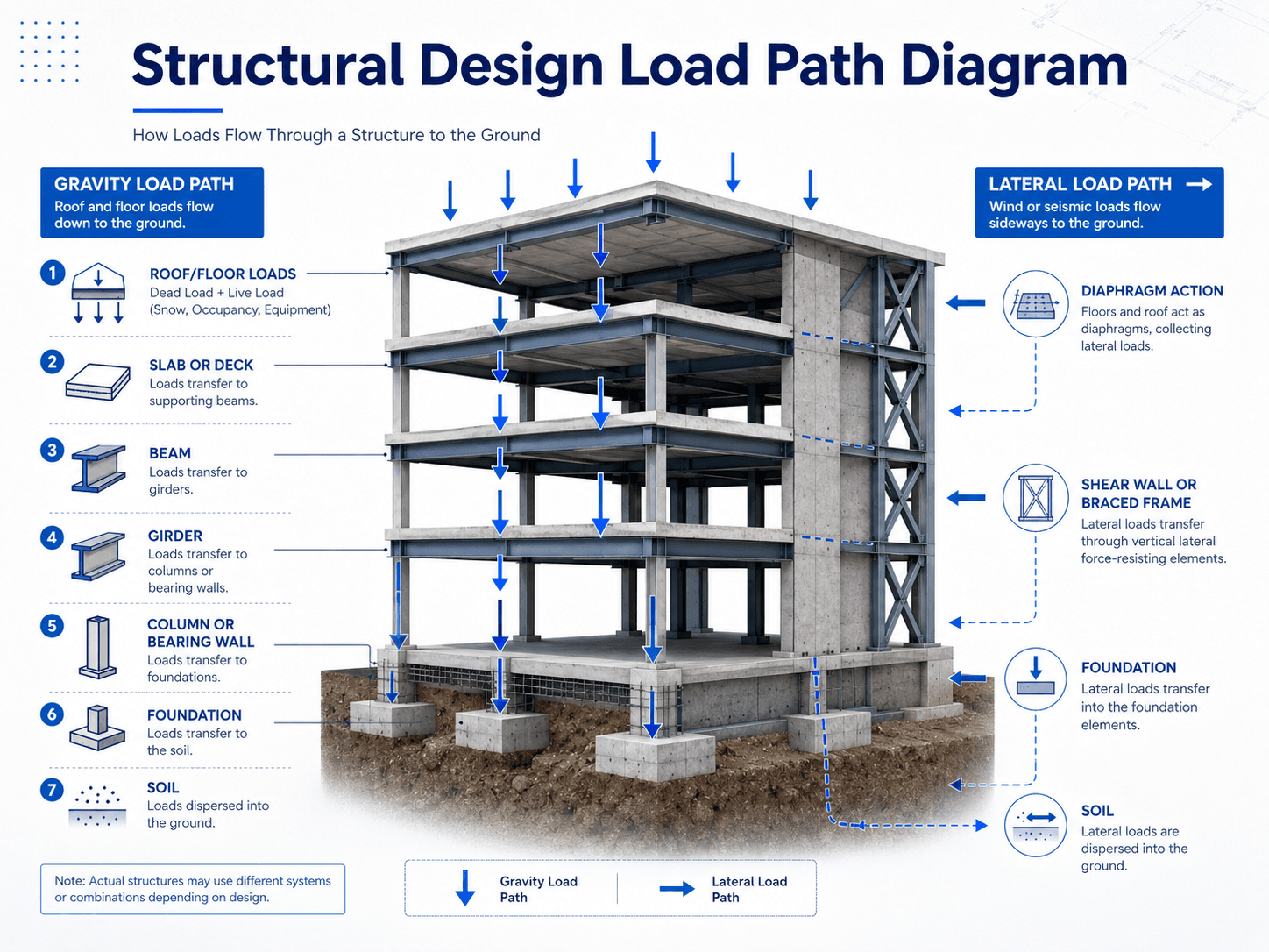
The first thing to look for is continuity. Every load needs a reliable route from the point of application to the supporting soil or rock.
What is Structural Design?
Structural design is the part of structural engineering that turns project requirements into a safe physical structure. It determines what structural system should be used, how large the members need to be, how forces move between members, how connections are detailed, how foundations receive loads, and whether the completed structure can perform throughout its intended life.
A useful way to understand structural design is to ask three questions: what loads act on the structure, where do those loads go, and what must each component do to resist them? Those questions connect structural design to structural loads, structural analysis, and load path analysis.
A shallow definition might describe structural design as “sizing beams and columns.” In practice, the system matters more than any single member. A beam can pass a bending check and still be part of a poor design if its support, connection, lateral bracing, deflection behavior, or foundation reaction has not been coordinated.
| Concept | What it does | How it fits into structural design |
|---|---|---|
| Structural analysis | Calculates reactions, shear, moment, axial force, drift, deflection, and other demands. | Provides the demand side of the design problem. |
| Structural design | Selects members, systems, materials, connections, and foundations to resist those demands. | Turns calculated demands into a buildable structural solution. |
| Structural detailing | Communicates reinforcement, welds, bolts, anchors, splices, dimensions, bearing, and construction requirements. | Makes the intended load path buildable and inspectable. |
| Structural review | Checks assumptions, drawings, calculations, connections, load path, and constructability. | Reduces the risk of missed system-level issues. |
Structural Design Process
The structural design process usually begins with project criteria and ends with drawings, details, calculations, and construction coordination. It is not a straight line. Engineers often iterate because changing a span, material, wall location, connection type, or foundation assumption changes forces elsewhere in the structure.
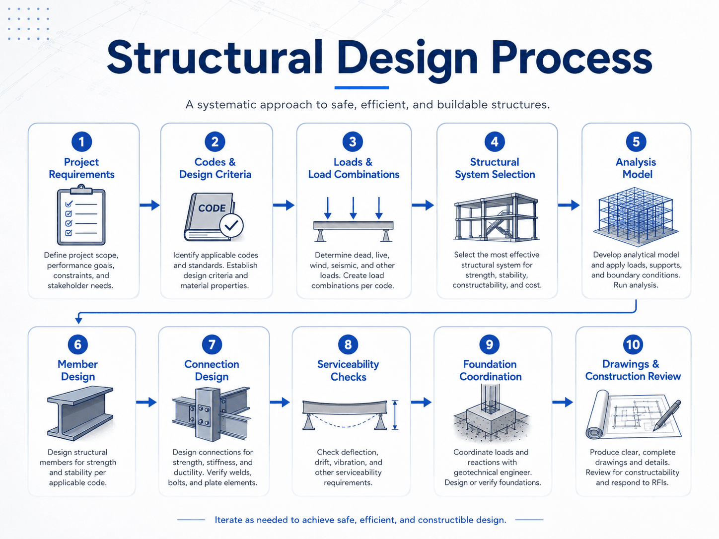
1. Define the project requirements
The engineer starts by understanding the structure’s purpose, occupancy, geometry, architectural constraints, durability needs, site conditions, and performance expectations. A warehouse, school, pedestrian bridge, high-rise building, retaining wall, residential addition, and equipment platform all place different demands on the design.
2. Establish loads and design criteria
The next step is to identify gravity, lateral, environmental, soil, water, equipment, and temporary construction loads. The governing design case is often not the largest single load, but the load combination that produces the most critical bending, shear, drift, uplift, overturning, or foundation reaction.
3. Select the structural system
System selection determines how loads move. Common systems include beam-and-column frames, load-bearing walls, shear walls, braced frames, moment frames, trusses, slabs, arches, shells, and composite systems. The best system balances strength, stiffness, cost, construction sequence, architectural layout, and durability.
4. Analyze, design, detail, and coordinate
Analysis estimates forces and movements. Design selects members and details that can resist those demands. Detailing communicates the design through plans, sections, schedules, and notes. Coordination checks that the structural design works with architecture, geotechnical assumptions, mechanical systems, construction tolerances, and field sequencing.
Load Path is the Heart of Structural Design
Load path is the route that forces follow through a structure. In gravity design, roof and floor loads typically move into slabs or decks, then joists or beams, then girders, columns, bearing walls, foundations, and soil. In lateral design, wind or seismic forces move through diaphragms, collectors, shear walls, braced frames, moment frames, foundations, and the ground.
This concept matters because structural problems often occur at transitions. Wall openings, transfer girders, offset columns, discontinuous shear walls, diaphragm edges, collector lines, anchor groups, and beam-to-column joints can all interrupt or concentrate force flow.
Trace the force from where it is applied to where it enters the ground. If any step requires the phrase “it just gets picked up somewhere,” the load path needs more review.
| Load path question | What to verify | Common weak point |
|---|---|---|
| Where does the load start? | Roof, floor, wall, equipment, façade, soil, water, wind, or seismic demand. | Forgetting equipment, storage, drifted snow, uplift, or construction loads. |
| What collects the load? | Deck, slab, diaphragm, wall, tributary area, or collector element. | Assuming a diaphragm or slab can transfer load without checking its actual capacity and detailing. |
| What transfers the load? | Beams, girders, walls, braces, collectors, drag struts, columns, anchors, and connections. | Connection forces, eccentricities, missing collectors, or weak support details. |
| Where does the load leave the structure? | Footings, mats, piles, piers, grade beams, walls, bearing soils, or rock. | Foundation reactions that do not match geotechnical assumptions or existing support conditions. |
Loads Considered in Structural Design
Structural loads are the forces, pressures, weights, accelerations, restraints, and environmental effects a structure must resist. Some loads are permanent, some change with occupancy, some depend on the site, and some only occur during construction or extreme events.
| Load type | What it represents | Engineering implication |
|---|---|---|
| Dead load | Permanent weight of structural members, finishes, façade, fixed equipment, and built-in items. | Controls baseline gravity demand and affects foundation reactions throughout the life of the structure. |
| Live load | Occupancy, furniture, storage, vehicles, people, and movable use-related loads. | Can control floor beams, slabs, columns, deflection, vibration, and local framing decisions. |
| Snow and rain load | Environmental roof loading from accumulated snow, drifting, ponding, or rainwater. | Can govern roof framing, roof slope decisions, drainage reliability, and ponding stability checks. |
| Wind load | Pressure, suction, uplift, overturning, and lateral force from wind acting on the structure. | Often controls lateral systems, cladding support, roof uplift, diaphragms, anchors, and overturning resistance. |
| Seismic load | Inertial forces caused by ground motion and the structure’s dynamic response. | Controls ductility, detailing, drift, diaphragm design, lateral force-resisting systems, and foundation anchorage. |
| Soil and hydrostatic load | Earth pressure, surcharge, groundwater pressure, and retained-fluid pressure. | Can control basement walls, retaining walls, mat foundations, tanks, uplift checks, and drainage details. |
| Thermal and restraint effects | Expansion, contraction, shrinkage, creep, temperature gradients, and restrained movement. | Can affect long structures, concrete cracking, bearings, joints, cladding interfaces, and connection forces. |
| Construction load | Temporary loads from equipment, shoring, stored materials, formwork, sequencing, or incomplete framing. | May govern temporary stability before the permanent structural system is complete. |
What Controls Structural Design?
The controlling design condition is the check that governs the final structural decision. Sometimes that is strength. Other times it is deflection, drift, vibration, fire rating, foundation settlement, connection geometry, reinforcement congestion, member depth, or construction access.
| Controlling issue | Where it often appears | How it changes the design |
|---|---|---|
| Strength | Heavily loaded beams, columns, walls, slabs, connections, and foundations. | May require larger members, more reinforcement, stronger connections, or a different structural layout. |
| Deflection | Long-span beams, floors, roofs, cantilevers, façade supports, and serviceability-sensitive spaces. | May require deeper members even when strength checks pass. |
| Drift | Tall buildings, flexible frames, wind-governed structures, and seismic systems. | May require stiffer lateral systems, additional walls, bracing, moment frames, or diaphragm improvements. |
| Vibration | Long-span floors, pedestrian bridges, stairs, gyms, offices, labs, and equipment platforms. | May require stiffness, mass, damping, span changes, or layout changes instead of only added strength. |
| Connection capacity | Steel frames, timber connections, precast connections, anchors, braced frames, and transfer details. | May control member orientation, plate thickness, bolt layout, weld size, anchor spacing, or erection sequence. |
| Foundation behavior | Soft soils, expansive soils, high groundwater, heavy columns, retaining structures, and lateral systems. | May control footing size, pile layout, mat thickness, settlement limits, uplift resistance, or wall design. |
| Constructability | Congested reinforcement, tight weld access, deep beams, transfer levels, and existing-building modifications. | May require simpler details, different member sizes, revised sequencing, or more practical connection geometry. |
The final member size is often controlled by serviceability, connection detailing, construction tolerances, or architectural depth limits rather than pure strength.
Structural Systems and Materials
Structural design is shaped by the system and material selected. A steel frame, reinforced concrete frame, timber structure, masonry wall building, truss system, and high-rise lateral system all solve the same basic problem—safe force transfer—but they do it with different stiffness, ductility, connection behavior, construction sequence, and detailing needs.
| System or material | Where it is useful | Design concern to watch |
|---|---|---|
| Steel frames | Open layouts, long spans, industrial buildings, commercial framing, braced frames, and moment frames. | Buckling, lateral bracing, connection forces, fire protection, corrosion, vibration, and erection sequencing. |
| Reinforced concrete | Slabs, beams, columns, walls, parking structures, foundations, podiums, and durable building systems. | Reinforcement detailing, cracking, shear, punching shear, deflection, development length, and construction tolerances. |
| Timber and engineered wood | Residential buildings, light-frame construction, mass timber, roof framing, floors, and sustainable structural systems. | Moisture, connection detailing, fire behavior, creep, vibration, shrinkage, and diaphragm load transfer. |
| Masonry structures | Load-bearing walls, shear walls, façades, schools, low-rise buildings, and fire-resistant wall systems. | Reinforcement, grouting, cracking, out-of-plane bending, seismic detailing, and wall openings. |
| Trusses | Long-span roofs, bridges, towers, open-web systems, and efficient lightweight framing. | Member axial forces, joint detailing, compression buckling, camber, handling, and erection stability. |
| Shear walls and braced frames | Lateral resistance for wind and seismic loads in buildings with defined force-resisting lines. | Collector forces, overturning, anchorage, diaphragm transfer, drift compatibility, and foundation tie-downs. |
For deeper material-specific design context, start with steel design, concrete design, and timber design.
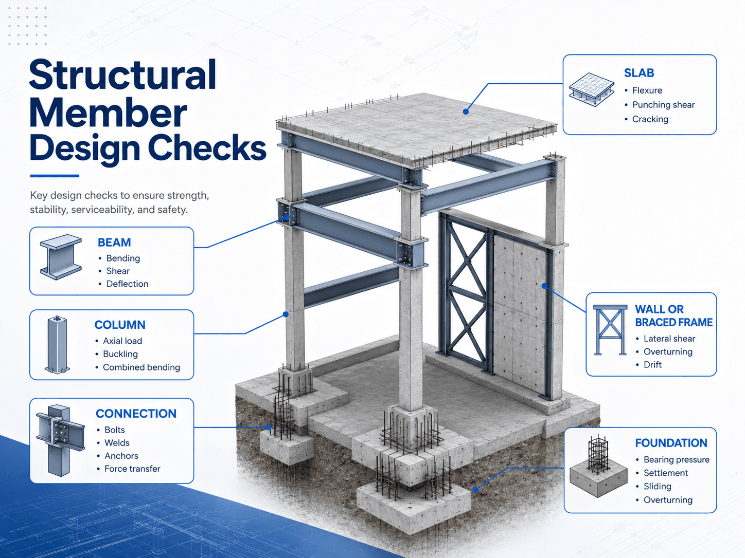
Structural Member Design Checks
Structural members are checked for more than simple strength. A member may need to resist bending, shear, axial force, torsion, combined loading, buckling, deflection, vibration, cracking, uplift, sliding, overturning, or connection demand depending on its role in the structure.
| Component | Typical checks | What a weak check can cause |
|---|---|---|
| Beams and girders | Bending, shear, deflection, bearing, lateral-torsional buckling, and vibration. | Excessive sag, cracking, instability, connection distress, or overstressed supports. |
| Columns | Axial load, buckling, slenderness, combined bending and axial force, base connection, and load transfer. | Instability, crushing, excessive drift sensitivity, or progressive load redistribution. |
| Slabs | Flexure, one-way shear, punching shear, cracking, deflection, vibration, and reinforcement layout. | Cracked finishes, ponding, punching failure, uncomfortable floors, or local overstress around supports. |
| Connections | Bolts, welds, anchors, bearing, plate bending, prying, eccentricity, and force transfer. | Local failure at the point where otherwise adequate members must transfer force. |
| Lateral systems | Story shear, drift, overturning, collector forces, diaphragm transfer, anchorage, and ductility. | Excessive lateral movement, damage concentration, torsional response, or incomplete lateral load path. |
| Foundations | Bearing pressure, settlement, sliding, overturning, uplift, punching shear, and soil-structure interaction. | Differential movement, rotation, cracking, serviceability problems, or loss of support. |
Strength, Stability, and Serviceability
Structural design is not finished when a member is strong enough. A structure also has to remain stable and usable. Strength checks ask whether the structure can resist demand without reaching a limit state. Stability checks ask whether the system or member can avoid buckling, overturning, sliding, or excessive second-order effects. Serviceability checks ask whether the structure performs acceptably under normal use.
| Design category | Question it answers | Examples |
|---|---|---|
| Strength | Can the member or system resist the required loads? | Bending strength, shear strength, axial capacity, connection capacity, anchor strength, and foundation bearing. |
| Stability | Can the structure keep its shape and equilibrium under load? | Column buckling, lateral-torsional buckling, overturning, sliding, frame stability, and bracing adequacy. |
| Serviceability | Will the structure remain usable and comfortable? | Deflection, drift, vibration, cracking, settlement, ponding, façade movement, and finish damage. |
| Durability | Will the structure remain reliable over time? | Corrosion protection, freeze-thaw exposure, moisture detailing, fire resistance, fatigue, and long-term creep. |
Structural Drawings and Design Deliverables
Structural design becomes useful to a project when it is communicated clearly. Calculations explain why the design works, but drawings and details show how the structure is built. A strong resource page on structural design should make this connection clear because many beginners confuse the engineering process with the final drawing set.
| Deliverable | What it communicates | Why it matters |
|---|---|---|
| General structural notes | Design criteria, materials, construction requirements, inspection notes, and reference standards. | Sets project-wide expectations before individual plans and details are read. |
| Foundation plans | Footings, piles, piers, grade beams, slabs, walls, anchor bolts, and foundation elevations. | Connects superstructure reactions to soil and geotechnical assumptions. |
| Framing plans | Beam, joist, girder, slab, wall, column, and deck layout by level. | Shows how gravity loads move through the structure. |
| Lateral system plans | Shear walls, braced frames, moment frames, diaphragms, collectors, chords, and anchorage. | Shows how wind and seismic forces are collected and transferred. |
| Sections and details | Connections, reinforcement, bearing, welds, bolts, anchors, splices, interfaces, and special conditions. | Turns design intent into buildable instructions. |
| Schedules | Columns, beams, footings, walls, reinforcement, connections, lintels, and other repeated elements. | Reduces drawing clutter and keeps repeated design information consistent. |
Senior Engineer Structural Design Review Checklist
A strong structural design review does not only ask whether calculations are complete. It checks whether the structural concept, analysis assumptions, member design, connections, load path, drawings, and field conditions agree with each other.
Start with the load path, then review loads and criteria, then verify the analysis model, then check governing members, then check connections and foundations, then compare the drawings against the calculations. The order matters because detailed member checks can hide a larger system problem.
| Review check | What to look for | Why it matters |
|---|---|---|
| Load path continuity | Clear gravity and lateral force routes from roof/floor to foundation and soil. | Incomplete force transfer can make locally adequate members part of an unsafe system. |
| Load criteria | Dead, live, snow, wind, seismic, soil, equipment, and temporary loads are appropriate for the project. | Wrong load assumptions can control every downstream design decision. |
| Boundary conditions | Supports, fixity, releases, diaphragm assumptions, bracing, and soil support match reality. | Analysis output is only useful if the model represents the intended structural behavior. |
| Governing limit states | Strength, stability, deflection, drift, vibration, cracking, settlement, and durability checks are all considered. | The most critical design issue is not always the highest stress ratio. |
| Connection design | Bolts, welds, anchors, bearing plates, collectors, splice details, and eccentricities are coordinated. | Connections often control how the designed load path actually works in the field. |
| Foundation coordination | Column loads, wall loads, uplift, overturning, lateral reactions, bearing pressures, and settlement criteria align with geotechnical assumptions. | A safe superstructure still depends on support conditions below grade. |
| Drawing consistency | Plans, sections, details, schedules, notes, and calculation assumptions all describe the same structure. | Construction errors often come from ambiguous or inconsistent documentation rather than missing calculations. |
Example: Removing a Load-Bearing Wall
A common structural design situation is a remodel where a load-bearing wall is removed to create an open floor plan. The design is not simply “replace the wall with a beam.” The engineer has to identify what the wall was carrying, where the new beam reactions will go, and whether the existing foundation can support the concentrated loads.
Design sequence
The engineer would typically determine the tributary roof and floor loads, select a beam that satisfies bending, shear, and deflection, design posts or columns at each end, check the beam-to-post and post-to-foundation load transfer, and verify that the supporting slab, footing, pier, or foundation wall can receive the new concentrated reactions.
Engineering meaning
The key lesson is that removing a wall changes the load path. Loads that were previously distributed along a wall may become concentrated at two or more points. That can control post size, bearing details, new footings, header depth, ceiling clearances, and constructability.
Engineering Judgment and Field Reality
Real structural design is affected by conditions that are hard to capture in a clean textbook diagram. Existing buildings may have undocumented framing, hidden deterioration, field-modified members, unverified foundations, unexpected openings, weak connections, or construction tolerances that do not match the original drawings.
New construction also requires judgment. A theoretical system may be efficient on paper but difficult to build, coordinate, inspect, or detail. Engineers often adjust framing layouts to simplify connections, avoid excessive member depth, improve erection stability, reduce congestion, maintain architectural clearances, or create a more reliable load path.
A structure is built from details, not from analysis diagrams. If a connection, anchor, weld access, reinforcement splice, bearing surface, or construction sequence cannot be executed reliably, the design needs refinement.
When This Breaks Down
Simplified structural design explanations break down when they ignore system behavior, unusual load paths, dynamic effects, nonstandard materials, deterioration, or construction sequencing. The diagrams and workflows on this page are useful learning tools, but real design often requires project-specific analysis and coordination.
- Discontinuous lateral systems: Offset shear walls, transfer levels, soft stories, and irregular diaphragms can create complex collector and overturning demands.
- Existing structures: Unknown member sizes, hidden damage, previous modifications, and uncertain foundations can control the design more than the proposed new framing.
- Dynamic or vibration-sensitive structures: Footbridges, long-span floors, machinery supports, and tall slender structures may require checks beyond simple static strength.
- Temporary construction stages: A structure may be stable after completion but vulnerable before the full bracing, diaphragm, slab, or wall system is installed.
- Connection-controlled designs: The governing issue may be anchor capacity, bolt spacing, weld access, plate bending, eccentricity, or load transfer through a joint.
Common Mistakes and Practical Checks
The most common structural design mistakes usually come from treating members as isolated pieces, trusting software output without checking assumptions, or failing to coordinate the load path with construction details.
- Ignoring the full load path: A beam check is incomplete if the support, connection, post, footing, and soil reaction are not also considered.
- Using analysis software as the design answer: Models produce results, but the engineer still needs to verify supports, releases, load combinations, stiffness assumptions, mesh behavior, and boundary conditions.
- Underestimating lateral loads: Gravity framing may look dominant, but wind, seismic, uplift, drift, or diaphragm transfer can control the structural system.
- Missing serviceability: A member that passes strength may still deflect, vibrate, crack, drift, or settle more than the structure can tolerate.
- Detailing weak connections: Connections need to transfer the actual forces that the structural system depends on, including eccentricities and construction tolerances.
- Forgetting constructability: Reinforcement congestion, weld access, anchor edge distance, shoring needs, and erection sequence can make a theoretically sound design difficult to build.
The biggest mistake is designing the member but not the system. Structural design should always connect calculations, details, drawings, and field conditions back to the same load path.
Codes, Standards, and Practical Design References
Structural design depends on the governing building code, adopted standards, jurisdictional requirements, owner criteria, material-specific specifications, and site-specific conditions. A resource page can explain the concepts, but final design criteria are established by the applicable project requirements.
- ASCE/SEI 7: ASCE/SEI 7-22 Minimum Design Loads and Associated Criteria for Buildings and Other Structures covers minimum design loads and load combinations used for general structural design, including dead, live, soil, flood, snow, rain, atmospheric ice, earthquake, wind, and other load effects.
- Material standards: Steel, concrete, masonry, timber, aluminum, and composite designs rely on material-specific design specifications and detailing rules in addition to the general loading criteria.
- Engineering use: Engineers use standards to establish design loads, combinations, material resistance, serviceability criteria, detailing requirements, and documentation expectations for a specific project.
Frequently Asked Questions
Structural design is the engineering process of creating a safe load-resisting system by selecting structural systems, sizing members, checking loads and serviceability, detailing connections, and coordinating foundations so forces can move safely from the structure into the ground.
Structural analysis estimates demands such as reactions, shear, bending moment, axial force, drift, and deflection. Structural design uses those demands to choose member sizes, reinforcement, connections, lateral systems, and details that satisfy strength, serviceability, constructability, and code requirements.
Structural design commonly considers dead load, live load, roof load, snow, wind, seismic force, soil pressure, hydrostatic pressure, equipment loads, construction loads, thermal effects, and load combinations that represent realistic governing conditions for the structure.
Load path is important because every force needs a continuous route through slabs, beams, girders, columns, walls, bracing, connections, foundations, and soil. A member may look strong by itself, but the overall design can still be unsafe if the load path is interrupted.
Structural design may be controlled by strength, stability, deflection, vibration, drift, connection forces, foundation reactions, constructability, durability, fire resistance, or architectural constraints. The controlling check depends on the structure, material, span, load path, and project requirements.
Summary and Next Steps
Structural design is the process of creating a safe, stable, serviceable, durable, and buildable structural system. It combines loads, load paths, structural analysis, material behavior, member checks, connections, foundations, drawings, and field coordination into one complete design.
The most important practical idea is continuity. A good design traces gravity and lateral loads from where they begin to where they enter the ground, then verifies that each member, connection, and foundation element can perform its role.
Where to go next
Continue your learning path with related Turn2Engineering resources.
-
Structural Analysis
Learn how engineers calculate reactions, shear, bending moment, axial force, drift, and deflection before design decisions are finalized.
-
Load Path Analysis
Study how forces move through diaphragms, beams, columns, walls, foundations, and soil.
-
Structural Safety Systems
Explore the systems and design decisions that help structures resist failure, instability, and unsafe performance.