
Key Takeaways
- Core idea: A leach field is the soil absorption area that receives septic tank effluent and provides final treatment through controlled infiltration.
- Engineering use: Designers use wastewater flow, soil conditions, groundwater separation, setbacks, slope, and available area to select and size the field.
- What controls it: The biggest controls are daily design flow, allowable soil loading rate, limiting layers, distribution quality, and local onsite wastewater rules.
- Practical check: A drain field that infiltrates too slowly can back up, but a field that infiltrates too quickly may not provide enough soil treatment.
Table of Contents
Introduction
Leach field design is the process of sizing and laying out the soil absorption area of a septic system so wastewater effluent can be distributed, treated, and infiltrated safely. A good design matches daily flow to soil capacity while protecting groundwater, avoiding hydraulic overload, and leaving enough space for maintenance and replacement.
How a Leach Field Treats Septic Effluent
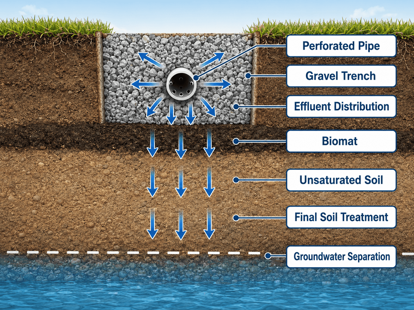
The most important part of the image is the vertical separation between the infiltrative surface and groundwater. That soil depth is where much of the treatment and polishing occurs.
What is Leach Field Design?
Leach field design, also called septic drain field design or soil absorption field design, determines how septic tank effluent is distributed into the ground after primary treatment in the tank. The design must provide enough infiltrative area for the expected wastewater flow while keeping the effluent in suitable soil long enough for treatment.
In water resources engineering, the leach field is a small onsite wastewater treatment system. It manages household or building wastewater at the site instead of sending it to a centralized treatment plant. The soil becomes part of the treatment train, so the design is controlled as much by soil profile and groundwater separation as by pipe layout.
A leach field usually begins after the septic tank design portion of the system. The tank removes settleable solids and floating scum before liquid effluent moves to the distribution box, dosing system, chamber bed, trench network, or mound system.
Step-by-Step Leach Field Design Workflow
A leach field design should move from wastewater loading to soil acceptance to physical layout. Skipping directly to trench length is risky because the calculated field area may not fit once setbacks, slope, reserve area, groundwater separation, and distribution details are checked.
| Design step | What the designer checks | Why it matters |
|---|---|---|
| 1. Estimate daily design flow | Bedrooms, occupants, fixture count, building use, or locally prescribed wastewater flow. | This establishes the hydraulic load the absorption field must handle. |
| 2. Confirm septic tank pretreatment | Tank size, outlet tee, effluent filter, pumping access, and solids retention. | The leach field performs better when solids and grease stay in the tank. |
| 3. Evaluate soil and site conditions | Soil texture, structure, percolation behavior, slope, drainage, groundwater, and bedrock. | Soil conditions determine whether a conventional absorption trench is appropriate. |
| 4. Select allowable soil loading rate | Use the loading rate allowed by the soil evaluation and local onsite wastewater criteria. | The loading rate converts wastewater flow into required infiltrative area. |
| 5. Calculate required absorption area | Divide design flow by allowable loading rate, then adjust as required by system type and local rules. | This establishes the minimum soil absorption area before layout constraints are checked. |
| 6. Convert area into layout | Trench width, total trench length, number of laterals, spacing, chamber area, or mound footprint. | A good design must fit on the lot without overloading one part of the field. |
| 7. Check setbacks and reserve area | Wells, buildings, property lines, water bodies, utilities, driveways, trees, and future replacement area. | A field can be large enough hydraulically but still fail siting requirements. |
| 8. Review construction and maintenance access | Equipment routes, compaction risk, distribution box access, inspection points, and grading. | Poor construction or blocked access can shorten the field’s service life. |
The Design Objective: Match Flow to Soil Capacity
The main objective is to apply septic effluent to soil at a rate the site can accept and treat over many years. If the field is too small, overloaded, poorly distributed, or placed in unsuitable soil, the system can pond, back up into the building, or allow inadequately treated wastewater to reach groundwater.
What the leach field must do
A properly designed leach field must distribute flow evenly, maintain aerobic treatment in the unsaturated soil zone, avoid surfacing wastewater, and protect wells, streams, lakes, and neighboring properties. The layout also needs enough room for reserve or replacement area because soil absorption systems are long-term infrastructure, not disposable trenches.
Why the septic tank matters first
The leach field depends on the septic tank to keep solids, grease, and scum out of the dispersal area. If the tank is undersized, not pumped, or missing an effective outlet filter, solids can migrate into the field and accelerate clogging at the biomat and trench interface.
A leach field should be reviewed as a system: tank performance, effluent quality, distribution method, soil acceptance, groundwater separation, and maintenance access all affect whether the field lasts.
Leach Field Design Inputs and Outputs
Leach field design starts with site and flow inputs, then turns those inputs into a soil absorption area and a constructible layout. The same design flow can lead to very different field footprints depending on soil loading rate, trench width, distribution method, groundwater separation, and available space.
| Design item | Input or output? | How it affects leach field design |
|---|---|---|
| Daily wastewater flow | Input | Sets the hydraulic load that must be absorbed and treated by the soil. |
| Soil loading rate | Input | Converts flow into required infiltrative area using soil evaluation and local criteria. |
| Required absorption area | Output | Defines the minimum soil area needed before applying layout and code constraints. |
| Trench or chamber width | Design selection | Controls how much trench length is needed for a given absorption area. |
| Total trench length | Output | Determines how many laterals are needed and whether the field fits on the lot. |
| Groundwater and bedrock depth | Input | Controls whether a conventional field has enough vertical treatment separation. |
| Reserve area | Layout requirement | Protects space for future replacement if the original absorption field reaches the end of its useful life. |
Leach Field Sizing and Worked Example
The basic sizing relationship is simple: the field must provide enough infiltrative area for the design flow at an allowable soil loading rate. The details are not universal, because the allowable loading rate is normally selected from local onsite wastewater rules, soil evaluation results, and approved design methods.
- \(A\) Required infiltrative area, commonly expressed in square feet or square meters.
- \(Q\) Daily design flow, commonly based on bedrooms, occupants, fixtures, or code-prescribed wastewater flow.
- \(L\) Allowable soil loading rate, selected from site evaluation and applicable local design criteria.
For a trench system, the required area is then translated into trench length, trench width, number of laterals, and spacing. For chamber or mound systems, the same flow-to-soil-capacity logic applies, but the approved sizing basis may depend on the product, sand fill, pressure distribution, or local design manual.
Example: converting absorption area into trench length
Suppose a residential system has a design flow of 450 gallons per day and the approved soil loading rate is 0.45 gallons per square foot per day. The minimum infiltrative area would be \(450 / 0.45 = 1{,}000\) square feet before applying any additional local requirements, layout constraints, reserve area requirements, or system-specific adjustments.
If the design uses 3-foot-wide trenches, the total trench length based on bottom area would be approximately \(1{,}000 / 3 = 333\) feet. One possible layout might be four trenches about 84 feet long each, but that layout still has to satisfy trench spacing, maximum trench length, slope, setbacks, distribution, and reserve area rules.
The equation tells you the absorption area needed by hydraulic loading. It does not automatically prove the layout is acceptable, because groundwater separation, setbacks, slope, trench spacing, and reserve area still have to work on the actual site.
Soil Evaluation and Percolation Testing
Soil is the treatment medium in a leach field. A percolation test may be used to estimate how quickly water moves through soil, but a good site evaluation also considers soil texture, structure, color, mottling, restrictive layers, groundwater indicators, root channels, and seasonal wetness.
How percolation behavior affects design
Percolation rate helps describe how quickly water moves through a prepared soil test hole, but it should not be treated as the entire design. The most useful interpretation combines percolation behavior with the soil profile and the depth to groundwater, bedrock, or another restrictive layer.
| Perc or soil behavior | What it means | Design implication |
|---|---|---|
| Very fast infiltration | Effluent may move quickly through coarse sand or gravelly soil. | Additional treatment, greater separation, or a different design approach may be needed to protect groundwater. |
| Moderate infiltration | Soil accepts water while still providing treatment contact time. | A conventional trench or chamber system may be possible if setbacks and limiting layers are acceptable. |
| Slow infiltration | Fine-textured soil accepts water slowly and may remain wet for long periods. | The design may need a lower loading rate, larger area, dosing, or an alternative field type. |
| Restrictive or seasonally saturated soil | Groundwater, bedrock, dense clay, or a restrictive horizon limits treatment depth. | A mound, advanced treatment, pressure distribution, or other approved alternative may be required. |
Slow soil is a hydraulic problem
Fine-textured soils can restrict infiltration. If wastewater enters the field faster than the soil can accept it, effluent can pond in the trench, surface on the lawn, or back up toward the building. Larger fields, lower loading rates, dosing, or alternative systems may be needed.
Fast soil can be a treatment problem
Very coarse soil can move effluent quickly but may not provide enough contact time for treatment before water reaches groundwater or nearby wells. That is why leach field design is not simply about making wastewater disappear as quickly as possible.
Leach Field Layout and Siting Controls
After the required infiltrative area is estimated, the designer has to fit the system onto the site. This is where many designs become difficult: the field may need to avoid wells, buildings, property lines, utilities, steep slopes, driveways, water bodies, trees, drainage paths, and future replacement areas.
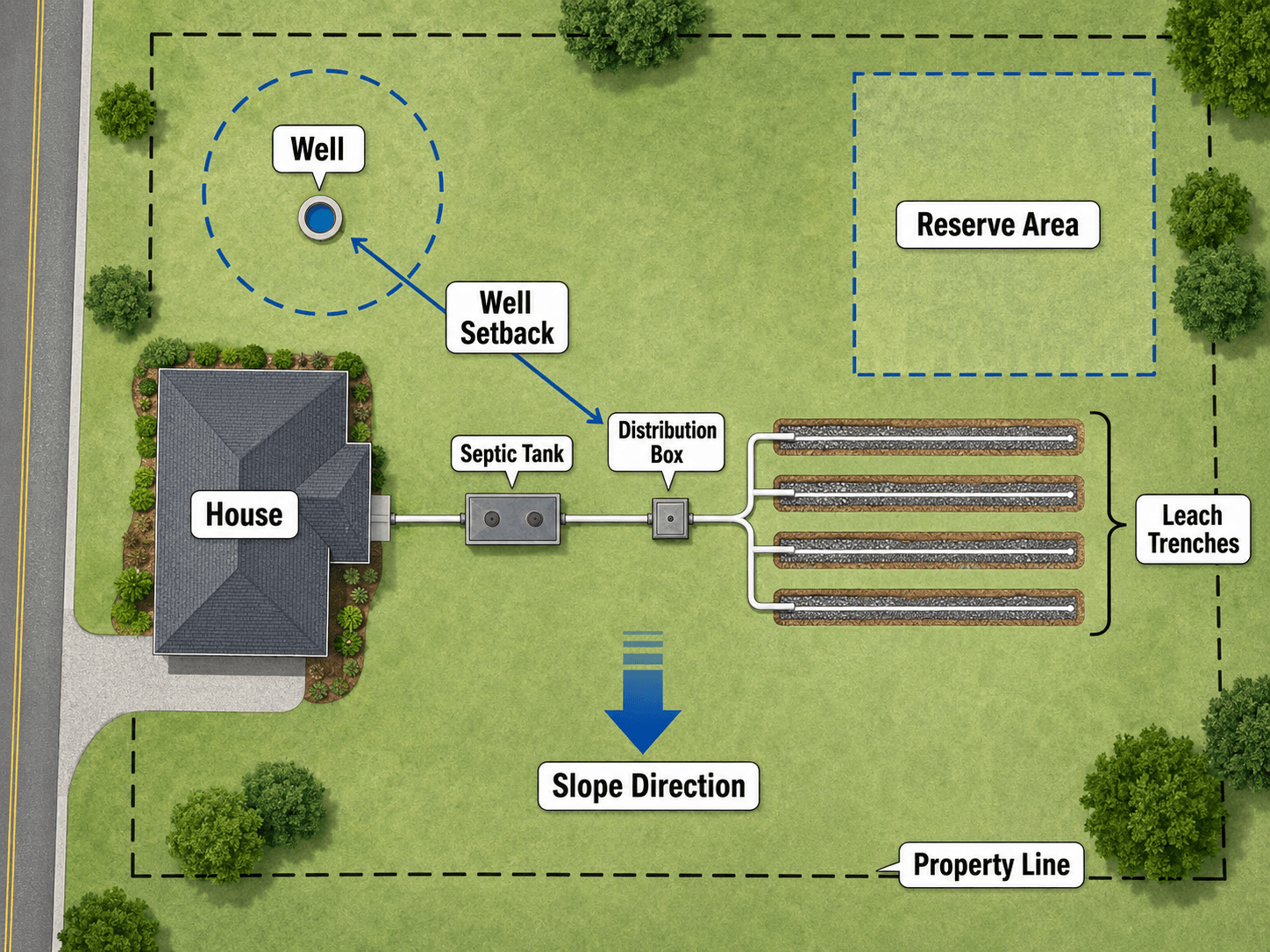
Distribution box and lateral balance
A distribution box or dosing system should spread effluent evenly across the field. If one trench receives most of the flow, it can fail early while other trenches remain underused. Field elevation, pipe alignment, construction tolerances, and settlement can all affect distribution.
Reserve area and long-term planning
Many onsite wastewater designs require a reserve area for future replacement. From a practical engineering standpoint, this area should be protected from grading changes, vehicle traffic, structures, and landscaping decisions that would make replacement impossible.
Common Leach Field Design Types
The best leach field type depends on soil, groundwater, slope, available area, wastewater strength, maintenance expectations, and local approval. A conventional trench is not always the right answer, especially on small lots or sites with shallow limiting layers.
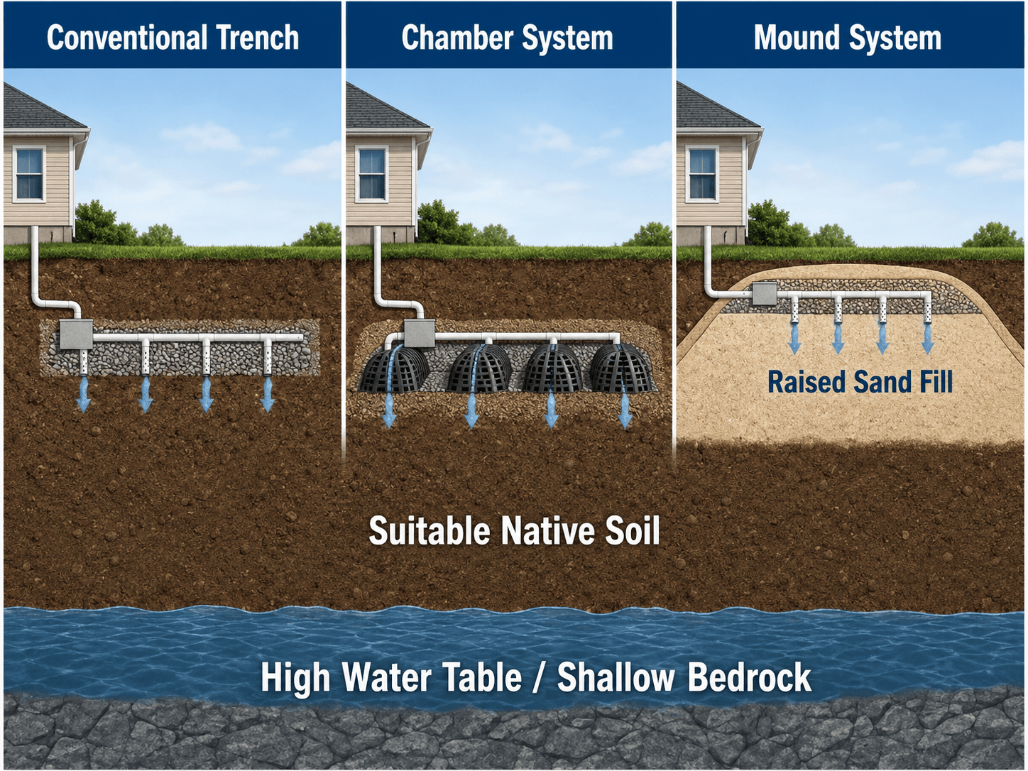
| System type | How it works | When it is commonly considered |
|---|---|---|
| Conventional gravel trench | Effluent flows through perforated pipe set in gravel-filled trenches. | Suitable soil, adequate depth to groundwater or bedrock, and enough field area. |
| Chamber system | Effluent is distributed through open-bottom chambers that create storage and contact area. | Sites where chamber systems are approved and can reduce gravel needs or improve constructability. |
| Mound system | Effluent is distributed in a raised sand fill bed above native soil. | Sites with shallow groundwater, shallow bedrock, or insufficient natural soil depth for a conventional field. |
| Pressure distribution | A pump doses effluent through a pressurized pipe network for more uniform application. | Sites needing better distribution, dosing control, or elevation gain from tank to field. |
| Drip distribution | Effluent is applied through shallow drip lines at controlled rates. | Some constrained or shallow sites where approved treatment and maintenance systems are provided. |
System selection decision table
| Site condition | Likely design direction | Reason |
|---|---|---|
| Suitable native soil with adequate depth | Conventional trench or chamber system | The soil can provide both infiltration and treatment when the field is properly sized. |
| Shallow groundwater or shallow bedrock | Mound system or other elevated/alternative system | The design may need to raise the infiltrative surface to maintain treatment separation. |
| Uneven gravity distribution risk | Pressure distribution | Dosing can help spread flow more evenly across laterals. |
| Limited available area | Chambers, advanced treatment, or approved alternative | Some alternatives can improve constructability or reduce field footprint where allowed. |
| Steep or irregular slope | Contour-oriented layout, pressure dosing, or engineered alternative | Slope affects distribution, breakout risk, erosion, and constructability. |
| Very sandy or gravelly soil | Additional treatment or design safeguards | Fast movement may reduce contact time before effluent reaches groundwater. |
Engineering Judgment and Field Reality
Leach field design is highly site-specific. Two lots with the same number of bedrooms can require very different field areas because soil profile, slope, groundwater, surface drainage, and available reserve area change the design more than the building footprint alone.
The field that looks easiest to build is not always the best location. A flat open lawn may still be a poor choice if it is compacted, seasonally wet, too close to a well, downslope of roof runoff, or needed as a future replacement area.
Biomat is both useful and risky
A biomat forms near the infiltrative surface as organic material and microorganisms accumulate. It helps treatment, but it also reduces infiltration over time. Good design and maintenance manage the biomat rather than pretending it will not develop.
Construction quality affects performance
Smearing trench bottoms, compacting soil with equipment, installing laterals out of level, or allowing sediment into pipes can reduce performance before the system is even used. For leach fields, careful construction is part of the design outcome.
Maintenance affects design life
The leach field is usually the most difficult part of a septic system to repair. Tank pumping, outlet filter cleaning, water conservation, grease control, and protection from vehicle traffic all help preserve the absorption area that the original design depends on.
Failure Modes and Troubleshooting Checks
The simplified design equation breaks down when field conditions do not match the assumptions behind the loading rate or layout. A leach field is not just a square footage calculation; it is a soil treatment system affected by water movement above, within, and below the field.
| Failure symptom | Likely design or maintenance cause | What to review |
|---|---|---|
| Wet spots or ponding over the field | Hydraulic overload, slow soil acceptance, shallow groundwater, or surface runoff entering the field. | Design flow, soil loading rate, trench ponding, grading, and drainage paths. |
| Sewage backup into the building | Saturated absorption area, clogged tank outlet, blocked pipe, or overloaded field. | Septic tank condition, outlet filter, distribution box, and trench water levels. |
| Odor near the field | Surfacing effluent, saturated soil, short-circuiting, or poor venting. | Field saturation, dosing frequency, soil condition, and evidence of breakout. |
| One trench failing before others | Uneven distribution, settled distribution box, pipe slope error, or lateral blockage. | Distribution box leveling, flow split, pipe alignment, and lateral condition. |
| Early leach field failure | Solids carryover, grease loading, soil compaction, poor construction, or undersizing. | Tank maintenance history, effluent filter, construction records, and soil disturbance. |
| Reduced performance after storms | Surface water routed toward the field or seasonal high groundwater reducing treatment depth. | Roof drains, swales, driveway runoff, grading, and groundwater indicators. |
Do not diagnose a leach field problem from the surface alone. A wet lawn, odor, or slow drain may involve the tank, distribution box, pipe network, soil, groundwater, or household water use.
Senior Engineer Review Checklist for Leach Field Design
A useful leach field review checks more than trench length. The reviewer should confirm that the field can accept flow, treat effluent, fit the site, survive construction, and remain maintainable over the life of the system.
Start with design flow, confirm septic tank pretreatment, evaluate soil and limiting layers, select the allowable loading rate, size the infiltrative area, lay out the field, check setbacks and reserve area, then review distribution, constructability, drainage, and maintenance access.
| Review check | What to look for | Why it matters |
|---|---|---|
| Design flow basis | Bedroom count, occupancy, fixtures, code-prescribed flow, or measured wastewater load. | The field area is only as reliable as the flow assumption used to size it. |
| Septic tank pretreatment | Tank volume, outlet tee, effluent filter, pumping access, and solids management. | Solids leaving the tank shorten leach field life and increase clogging risk. |
| Soil and limiting layer evaluation | Texture, structure, perc behavior, seasonal high groundwater, bedrock, restrictive horizons, and depth of suitable soil. | Soil controls both infiltration and final treatment. |
| Allowable loading rate | Use a loading rate supported by local criteria and the site evaluation. | An overly aggressive loading rate can produce chronic ponding or early failure. |
| Absorption area and trench length | Confirm the required infiltrative surface has been converted into a realistic field footprint. | A calculated area must become a layout that can actually be built and maintained. |
| Distribution method | Gravity laterals, distribution box, pressure dosing, pump chamber, or drip application. | Uniform loading reduces the chance that one trench fails while others remain unused. |
| Setbacks and reserve area | Clearances to wells, property lines, buildings, water bodies, utilities, and future replacement space. | A design that fits hydraulically may still be unacceptable if it cannot satisfy site constraints. |
| Surface drainage protection | Roof runoff, swales, driveway flow, ponding areas, and grading direction. | Stormwater can overload the soil absorption area even if wastewater flow is correctly sized. |
| Construction protection | Equipment routes, stockpile locations, trench bottom smearing, and compaction control. | Damaged soil structure can reduce infiltration before the system starts operating. |
Common Leach Field Design Mistakes
Most leach field problems trace back to one of three issues: the site was not evaluated correctly, the field was hydraulically overloaded, or the layout did not protect the soil treatment area over time.
- Designing from bedroom count alone: Bedrooms may set design flow, but soil and groundwater decide whether the field can actually work.
- Ignoring reserve area: A site can pass today’s layout and still create a future replacement problem if the reserve area is built over or compacted.
- Treating the perc test as the whole soil evaluation: Perc rate is useful, but soil profile, limiting layers, and seasonal wetness often control the real design risk.
- Letting surface water enter the field: Roof drains, swales, and driveway runoff can overload the field even when wastewater use is normal.
- Assuming all trenches load evenly: Poor distribution can make one lateral fail early while the remaining field capacity is not fully used.
- Copying a nearby system: Adjacent properties can have different groundwater depth, soil texture, slope, reserve area, and approval requirements.
Do not size a leach field by copying a neighbor’s system. Nearby lots can have different soils, groundwater depth, slope, reserve area, and regulatory constraints.
Codes, Manuals, and Design Guidance
Leach field design should be developed using the local onsite wastewater requirements that apply to the project location. National guidance is useful for understanding system types and design factors, but the final sizing, setbacks, testing, and approval process are usually controlled by the authority having jurisdiction.
- U.S. Environmental Protection Agency: EPA overview of conventional and alternative septic system types explains why septic system design varies with household size, soil type, slope, lot size, sensitive water bodies, climate, and local regulations.
- Project-specific criteria: Local health departments, environmental agencies, or onsite wastewater programs typically control allowable loading rates, setback distances, reserve area requirements, inspections, and permitted system types.
- Engineering use: Designers use public guidance to understand system options, then apply local criteria and site-specific investigation to select the actual leach field layout.
Frequently Asked Questions
Leach field, drain field, absorption field, and soil absorption area are often used to describe the same part of a septic system: the buried dispersal area where septic tank effluent is distributed into soil for final treatment and infiltration.
Leach field size is generally based on daily design flow divided by an allowable soil loading rate, then converted into trench, chamber, bed, or mound dimensions using local design criteria. The allowable loading rate depends on soil evaluation, percolation behavior, groundwater separation, and jurisdictional requirements.
A good leach field soil accepts wastewater at a controlled rate while still providing treatment. Extremely slow clayey soils can cause ponding and backups, while very fast sandy or gravelly soils may not provide enough treatment before effluent reaches groundwater.
A conventional leach field may not be suitable where groundwater is too close to the infiltrative surface. Depending on the site and local rules, a designer may need to use a mound system, pressure distribution, advanced treatment, or another alternative system to maintain vertical separation.
Common causes include undersizing, poor soil evaluation, excessive hydraulic loading, solids leaving the septic tank, uneven distribution, compacted soil, shallow groundwater, surface runoff entering the field, and lack of septic tank maintenance.
Summary and Next Steps
Leach field design turns septic tank effluent into a controlled soil absorption and treatment problem. The field must have enough area, suitable soil, reliable distribution, and adequate separation from groundwater or bedrock.
The best designs start with flow and soil evaluation, then test the layout against setbacks, slope, reserve area, system type, construction risk, and long-term maintenance. The result is not just a trench layout; it is an onsite wastewater treatment system.
Where to go next
Continue your learning path with related Turn2Engineering resources.
-
Septic Tank Design
Learn how the tank provides primary treatment before effluent reaches the leach field.
-
Groundwater Resources
Review why groundwater protection is central to onsite wastewater design.
-
How Wastewater Treatment Plants Work
Compare onsite soil treatment with centralized wastewater treatment processes.