
Key Takeaways
- Core idea: Electrical properties describe how a material responds to current flow, electric fields, charge storage, leakage, and voltage stress.
- Engineering use: They guide material selection for wires, contacts, insulation, semiconductors, circuit boards, sensors, motors, cables, and high-voltage parts.
- What controls it: Electrical behavior depends on bonding, electron mobility, band gap, temperature, moisture, contamination, geometry, frequency, and test conditions.
- Practical check: Resistivity is a material property, but resistance is object behavior; the same material can perform differently when length, area, temperature, or surface condition changes.
Table of Contents
Introduction
Electrical properties are material behaviors that describe how a material conducts current, resists current flow, stores electric field energy, or performs as an insulator. These properties help engineers choose materials for conductors, insulation, electronics, sensors, cables, motors, and high-voltage components where electrical performance must work with mechanical, thermal, and environmental constraints.
Electrical Properties Diagram: Conductivity, Resistivity, and Resistance
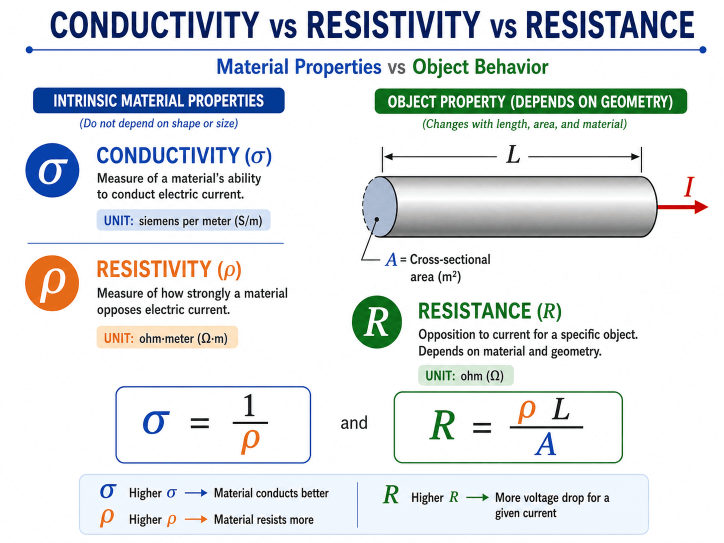
The key distinction is geometry. A material can have the same resistivity, but the resistance of a wire, trace, or contact changes when length, cross-sectional area, or current path changes.
What Are Electrical Properties?
Electrical properties explain current flow, insulation behavior, charge storage, leakage, and breakdown. The fastest way to understand them is to separate current-carrying properties from dielectric and insulation properties.
Electrical properties are the measurable characteristics that determine how a material behaves when exposed to electric current or an electric field. The most common electrical properties include electrical conductivity, electrical resistivity, dielectric strength, dielectric constant, dielectric loss, surface resistivity, volume resistivity, temperature coefficient of resistance, and tracking resistance.
In materials science, these properties connect atomic-scale behavior to real engineering decisions. A copper conductor, a polymer cable jacket, a ceramic capacitor dielectric, a silicon semiconductor, and a carbon-filled composite can all be selected or rejected based on how their electrical properties behave under service conditions.
Common electrical property units include conductivity in S/m, resistivity in \( \Omega \cdot m \), resistance in \( \Omega \), dielectric strength in kV/mm, dielectric constant as relative permittivity, dielectric loss as loss tangent or dissipation factor, surface resistivity in \( \Omega / \square \), and volume resistivity in \( \Omega \cdot m \) or \( \Omega \cdot cm \).
| Electrical property | What it describes | Common units or expression | Engineering use |
|---|---|---|---|
| Electrical conductivity, \( \sigma \) | How easily a material allows electric current to flow | S/m | Choosing wires, traces, busbars, contacts, conductive coatings, and grounding paths |
| Electrical resistivity, \( \rho \) | How strongly a material opposes current flow | \( \Omega \cdot m \) or \( \Omega \cdot cm \) | Comparing conductor and insulator materials independent of shape |
| Resistance, \( R \) | Opposition to current flow in a specific object | \( \Omega \) | Checking wire, trace, coil, heater, contact, and component behavior |
| Dielectric strength | Maximum electric field an insulating material can withstand before breakdown | kV/mm, V/m, or V/mil | Designing insulation thickness, voltage spacing, and high-voltage barriers |
| Dielectric constant | How strongly a material stores electric field energy compared with vacuum | Relative permittivity, \( \varepsilon_r \) | Capacitors, PCB substrates, cable insulation, embedded sensors, and RF design |
| Dielectric loss | Energy lost as heat when an insulating material is exposed to an alternating field | Loss tangent or dissipation factor | High-frequency electronics, insulation heating, signal integrity, and capacitor behavior |
| Surface resistivity | Resistance to leakage current across a material surface | \( \Omega / \square \) | Tracking resistance, static control, surface contamination, and creepage performance |
| Volume resistivity | Resistance to leakage current through the material bulk | \( \Omega \cdot m \) or \( \Omega \cdot cm \) | Bulk insulation comparison for polymers, ceramics, glass, and composite materials |
| Temperature coefficient of resistance | How resistance changes as temperature changes | 1/°C or ppm/°C | Wires, sensors, heaters, motors, precision resistors, and thermal drift checks |
| Tracking resistance / CTI | How well an insulating surface resists forming a conductive path under contamination and voltage stress | Comparative tracking index or test classification | Electrical housings, terminal blocks, connectors, and insulation exposed to dust or moisture |
Decide whether the material’s job is to carry current, block current, store electric field energy, control a signal, dissipate static charge, or withstand voltage. That choice determines which electrical property matters most.
Material Property vs Component Behavior
A major source of confusion is mixing material properties with the behavior of a finished part. Conductivity and resistivity describe the material, but resistance, capacitance, leakage current, and breakdown voltage depend on material properties plus geometry, temperature, frequency, surface condition, and manufacturing quality.
| Term | Material property or component behavior? | Depends on geometry? | Practical example |
|---|---|---|---|
| Conductivity | Material property | No, for isotropic bulk comparison | Copper has high conductivity compared with most engineering metals. |
| Resistivity | Material property | No, for isotropic bulk comparison | Rubber and many polymers have high resistivity compared with metals. |
| Resistance | Component behavior | Yes | A long, thin copper wire has more resistance than a short, thick copper bar. |
| Dielectric strength | Material test property | Test-condition dependent | Used to compare insulating materials under controlled breakdown testing. |
| Breakdown voltage | Component behavior | Yes | Thicker insulation usually withstands more voltage, but defects and field concentration can dominate. |
| Contact resistance | Interface behavior | Yes | Oxides, plating, pressure, roughness, and contamination can dominate a connection even when the bulk conductor is excellent. |
Use material properties to compare candidate materials, then calculate or test component behavior using the actual geometry, interfaces, temperature, environment, and operating conditions.
Conductors, Semiconductors, and Insulators
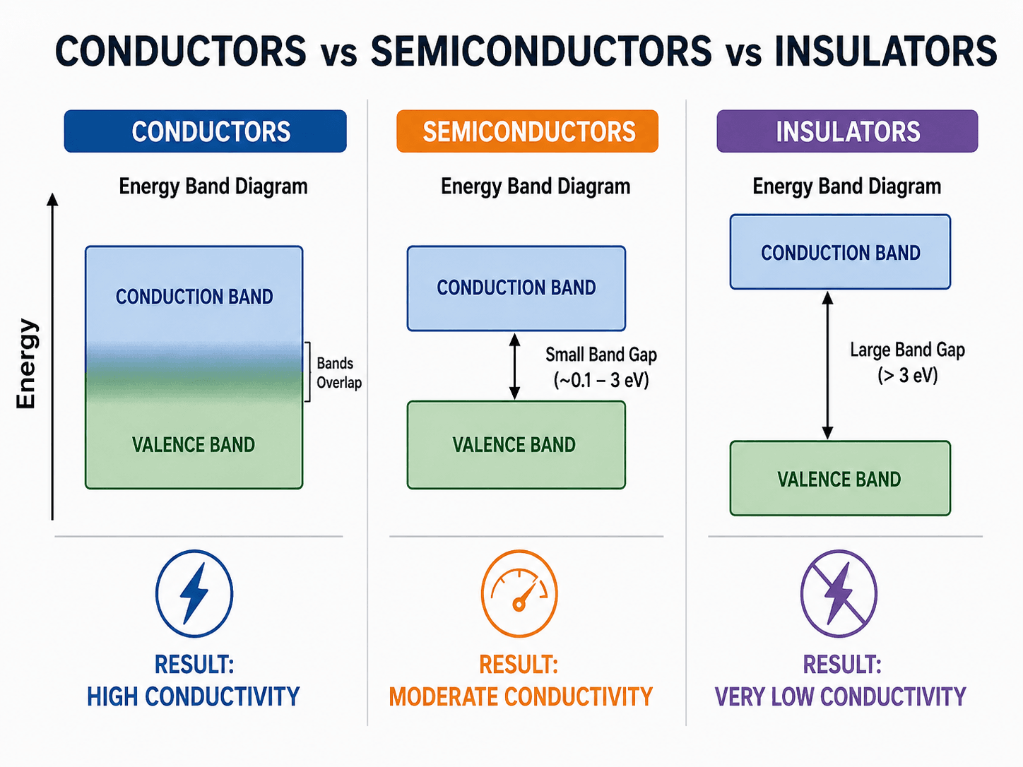
Materials are often grouped by how easily electrons can move through them. Conductors allow current flow easily, insulators strongly resist current flow, and semiconductors sit between those categories because their conductivity can be controlled by doping, temperature, light, or applied electric fields.
Conductors
Conductors have high conductivity and low resistivity. Metals such as copper and aluminum are common engineering conductors because they balance electrical performance with cost, density, manufacturability, corrosion behavior, and mechanical strength.
Semiconductors
Semiconductors have electrical behavior that can be intentionally changed. Silicon is the most familiar example, but semiconductor behavior is also important in sensors, power electronics, photovoltaics, integrated circuits, and temperature-sensitive materials.
Insulators
Insulators have high resistivity and are used to prevent unwanted current flow. Polymers, ceramics, glass, mica, and many composites are selected when voltage separation, dielectric strength, leakage control, and environmental durability matter more than current carrying capacity.
Conductivity vs Resistivity vs Resistance
Conductivity and resistivity compare materials. Resistance evaluates a specific object. The difference matters because a material can be highly conductive while the final part still has too much resistance due to length, area, temperature, or contact quality.
Conductivity and resistivity are intrinsic properties of a material. Resistance is not only a material property; it depends on the shape and size of the object. This is why the same copper alloy can have different resistance in a thin wire, a wide busbar, and a printed circuit board trace.
Conductivity \( \sigma \) and resistivity \( \rho \) are reciprocal properties for isotropic materials. Higher conductivity means current can flow more easily, while higher resistivity means the material more strongly opposes current flow.
Resistance increases as the current path length \( L \) increases and decreases as cross-sectional area \( A \) increases. A long, thin conductor can have much higher resistance than a short, thick conductor made from the same material.
The material form of Ohm’s law relates current density \( J \) to electric field \( E \). This is useful when thinking about current flow as a material response rather than only as a circuit component value.
- \( \sigma \) Electrical conductivity, usually in siemens per meter, S/m.
- \( \rho \) Electrical resistivity, usually in \( \Omega \cdot m \) or \( \Omega \cdot cm \).
- \( R \) Resistance of a specific object, measured in ohms, \( \Omega \).
- \( L \) Length of the current path through the object.
- \( A \) Cross-sectional area available for current flow.
- \( J \) Current density, or current per unit area.
- \( E \) Electric field strength applied to the material.
Dielectric Strength, Breakdown, and Insulation Behavior
Insulation performance is more than high resistivity. Dielectric strength, leakage current, dielectric loss, surface condition, tracking resistance, temperature, and moisture all affect whether a material can safely separate voltage.
Insulating materials are not simply materials that “do not conduct.” Real insulation must limit leakage current, resist surface tracking, withstand electric field stress, avoid excessive dielectric loss, and maintain performance as temperature, humidity, aging, and contamination change.
Dielectric strength
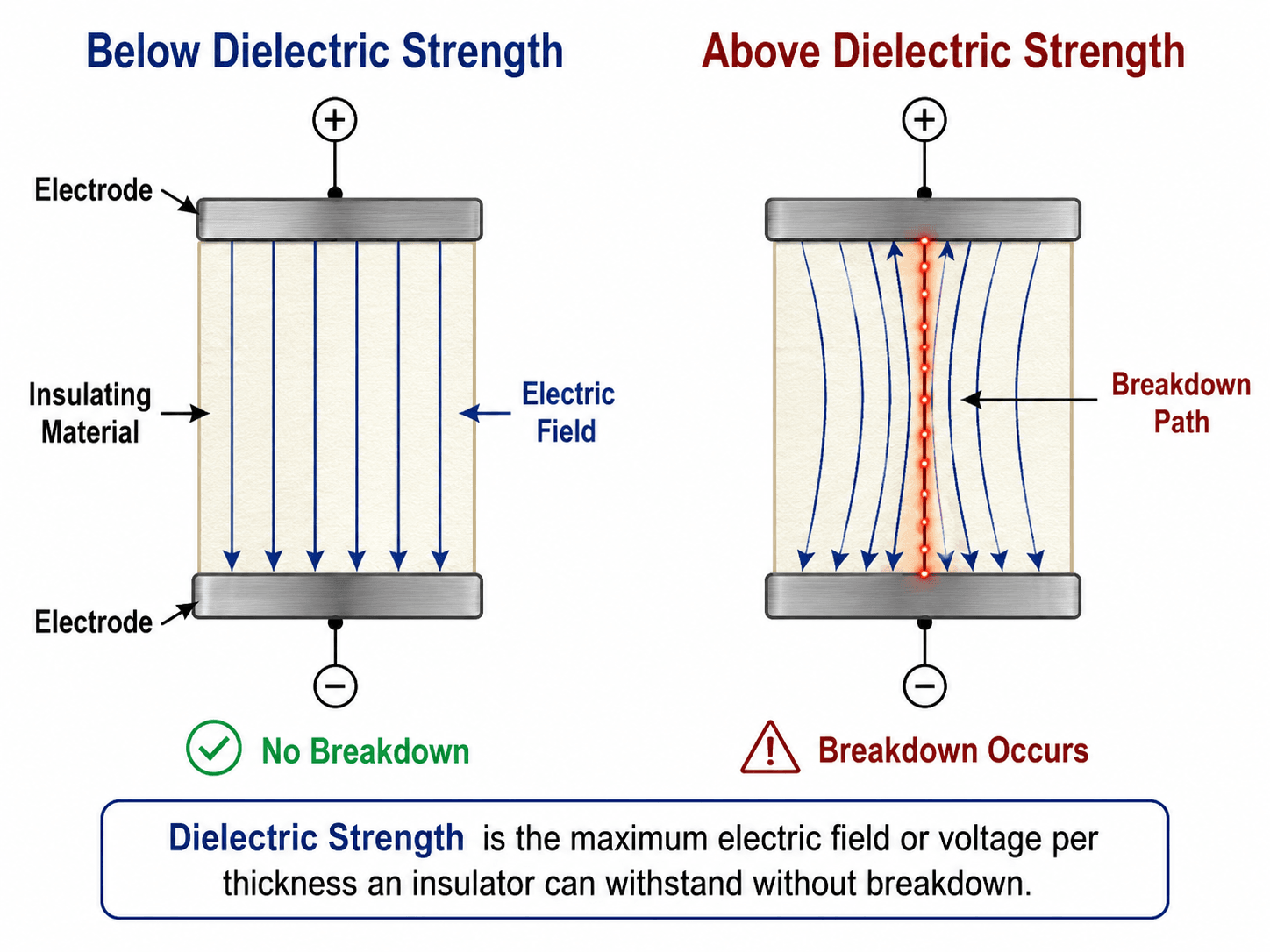
Dielectric strength is commonly expressed as voltage per thickness. A higher value generally means the material can withstand a stronger electric field before breakdown, but the actual result depends on thickness, voids, defects, temperature, humidity, electrode geometry, and voltage waveform.
Dielectric strength is a breakdown test value, not a recommended continuous working electric field. Real designs typically require margin because long-term voltage stress, partial discharge, surface contamination, and aging can reduce insulation reliability.
Dielectric constant
Dielectric constant, also called relative permittivity, describes how much electric field energy a material stores compared with vacuum. It matters in capacitors, PCB substrates, cable insulation, embedded sensors, RF systems, and high-speed electronics.
Dielectric loss
Dielectric loss describes energy converted to heat inside an insulating material when the electric field changes. A material can be a strong DC insulator but still perform poorly at high frequency if its dielectric loss is too high.
Surface tracking and CTI
Tracking is the formation of a conductive path across an insulating surface due to electrical stress, moisture, and contamination. Comparative tracking index, or CTI, is often used to compare how insulating materials resist surface tracking in applications such as connectors, terminal blocks, housings, and exposed insulation systems.
Electrical Properties by Material Class
Different material classes tend to have different electrical behavior because their bonding, electron mobility, band structure, defects, and microstructure are different. The table below gives a practical starting point for comparing electrical properties of metals, polymers, ceramics, semiconductors, composites, and carbon-based materials.
| Material class | Typical electrical behavior | Properties that usually matter | Engineering examples |
|---|---|---|---|
| Metals | High conductivity and low resistivity | Conductivity, resistivity, temperature coefficient, contact resistance, corrosion behavior | Copper wiring, aluminum busbars, conductive fasteners, connectors, grounding paths |
| Polymers | Usually insulating unless filled or modified | Volume resistivity, surface resistivity, dielectric strength, tracking resistance, moisture absorption | Cable jackets, housings, terminal blocks, insulating films, encapsulants |
| Ceramics | Often strong insulators or controlled dielectrics | Dielectric strength, dielectric constant, dielectric loss, thermal stability | Capacitors, spark plug insulators, high-voltage standoffs, electronic substrates |
| Semiconductors | Controlled conductivity based on carrier behavior | Band gap, carrier mobility, doping, temperature response, junction behavior | Silicon devices, sensors, photovoltaics, power electronics |
| Composites | Highly dependent on filler, fiber direction, and matrix material | Anisotropic conductivity, surface resistivity, dielectric behavior, filler loading | Carbon-filled plastics, ESD-safe materials, EMI shielding, fiber-reinforced components |
| Carbon-based materials | Can range from insulating to highly conductive depending on form and structure | Directional conductivity, contact resistance, filler network, percolation threshold | Graphite, carbon black compounds, carbon fiber composites, conductive coatings |
Do not assume every material in a class behaves the same way. Polymer fillers, ceramic formulation, alloy composition, semiconductor doping, and composite fiber orientation can all change electrical behavior significantly.
How Engineers Use Electrical Properties in Material Selection
Electrical properties become useful when they are tied to a design decision. Do not start by asking which material has the “best” electrical property. Start by identifying the job: carry current, block current, store electric field energy, control signal behavior, dissipate static charge, or withstand voltage. Each job points to a different controlling property.
- Conductors: selected for conductivity, voltage drop, temperature rise, corrosion behavior, joining method, cost, and weight.
- Insulators: selected for dielectric strength, leakage resistance, surface resistivity, tracking resistance, thermal aging, and moisture behavior.
- Electronics substrates: selected for dielectric constant, dielectric loss, thermal expansion, thermal conductivity, and manufacturing compatibility.
- Sensor materials: selected for predictable electrical response to temperature, strain, light, humidity, pressure, or chemical exposure.
- Static-control materials: selected for surface resistivity that is high enough to avoid shorts but low enough to prevent unwanted charge buildup.
Start by defining the electrical failure mode: voltage drop, overheating, leakage current, insulation breakdown, signal distortion, electrostatic discharge, or unstable sensor response. That failure mode determines which electrical property should control the material choice.
What Controls Electrical Properties?
Electrical properties are strongly affected by structure, chemistry, processing, and service environment. A datasheet value is useful only when the test conditions resemble the way the material will actually be used.
| Control or condition | Why it matters | Engineering implication |
|---|---|---|
| Temperature | Metals usually become more resistive as temperature rises, while semiconductors and polymers can behave differently. | Check operating temperature, temperature coefficient, heat rise, and derating instead of relying only on room-temperature values. |
| Temperature coefficient of resistance | Some materials have predictable resistance changes with temperature, while others are more nonlinear. | Important for precision resistors, wire sizing, heaters, motors, RTDs, thermistors, and thermal drift checks. |
| Geometry | Resistance depends on current path length and cross-sectional area even when material resistivity stays constant. | Use resistivity to compare materials, but calculate resistance for wires, traces, coils, and conductive paths. |
| Moisture and contamination | Water, dust, salt, oil, and surface films can reduce insulation performance and create leakage paths. | Surface resistivity, creepage distance, sealing, cleaning, and tracking resistance may control the design. |
| Frequency | Dielectric constant and dielectric loss can change with frequency. | High-frequency electronics require dielectric data at relevant frequency, not only DC insulation values. |
| Contact condition | Oxides, plating, pressure, roughness, corrosion, and contamination can add resistance at interfaces. | Bulk conductivity does not guarantee a low-resistance connection if the contact design is poor. |
| Microstructure and impurities | Grain boundaries, alloying elements, defects, fillers, and dopants change carrier movement. | The same base material can perform differently depending on grade, processing, heat treatment, and composition. |
| Anisotropy | Some materials conduct or insulate differently depending on direction. | Important for carbon fiber composites, laminates, graphite, crystals, and filled polymers. |
| Aging and electrical stress | Insulation can degrade from heat, partial discharge, UV exposure, chemicals, and repeated voltage stress. | Long-term reliability may require more margin than a short-term dielectric test suggests. |
Electrical Material Selection Decision Table
The best electrical property depends on the design job. A current path, dielectric barrier, RF substrate, ESD material, and high-voltage insulator are not selected using the same property.
Use this decision table to connect a design problem to the electrical property that should be checked first. In real material selection, the final choice usually depends on electrical performance, thermal limits, mechanical strength, manufacturability, cost, and environmental durability.
Define the electrical function, identify the failure mode to avoid, select the governing property, check the test conditions behind the data, then compare the result against mechanical, thermal, environmental, and manufacturing constraints.
| Design need | Primary property to check | Secondary checks | Practical watch-out |
|---|---|---|---|
| Carry current efficiently | High conductivity or low resistivity | Temperature coefficient, corrosion, joint resistance, weight, cost | A low-resistivity material can still overheat if the cross-section is too small. |
| Limit voltage drop | Resistance of the actual current path | Length, area, operating temperature, connection quality | Material conductivity alone does not predict voltage drop unless geometry is included. |
| Prevent leakage through insulation | High volume resistivity | Surface resistivity, moisture absorption, aging, operating temperature | Dry lab values may not represent humid, dirty, or aged service conditions. |
| Separate high voltage | Dielectric strength | Thickness, defects, partial discharge, creepage, clearance | Breakdown is not only a material issue; geometry and environment matter. |
| Store electric field energy | Dielectric constant | Dielectric loss, frequency, temperature stability | A high dielectric constant is not always better if loss or drift is unacceptable. |
| Control static charge | Surface resistivity | Humidity dependence, grounding path, contamination | Too conductive can short sensitive systems; too insulating can allow charge buildup. |
| Support high-frequency signals | Dielectric constant and dielectric loss | Frequency rating, thickness tolerance, thermal expansion | DC insulation data alone is not enough for RF or fast digital circuits. |
| Resist surface tracking | Tracking resistance or CTI | Surface resistivity, creepage, contamination, moisture | A clean dry surface may pass, but a contaminated surface can form a conductive path. |
How to Read Electrical Property Datasheets
Electrical property values should be read with their test conditions. A value without temperature, humidity, frequency, sample thickness, electrode arrangement, voltage waveform, and test method can be misleading, especially for polymers, ceramics, composites, and insulating materials.
Separate material properties from component behavior
Resistivity, conductivity, dielectric constant, and dielectric strength are material properties. Resistance, capacitance, breakdown voltage, leakage current, and voltage drop are component-level behaviors. A datasheet can support a design estimate, but geometry and operating conditions still need to be checked.
Check whether the value is DC, AC, or frequency-specific
Volume resistivity is often used as a DC-style insulation comparison, while dielectric constant and dielectric loss are usually frequency-dependent. For RF systems, high-speed electronics, sensors, cables, and capacitors, frequency can be as important as the material name.
Look for environmental assumptions
Moisture can reduce surface resistivity, contamination can create tracking paths, and temperature can change both conductor and insulator behavior. If the application is outdoors, humid, hot, dirty, or high-voltage, the environmental assumptions become part of the design.
Watch for directional data
Some materials have directional electrical behavior. Carbon fiber composites, graphite, laminates, crystals, and filled polymers may have different conductivity or resistivity through thickness than along the surface or fiber direction.
Engineering Judgment and Field Reality
Textbook explanations often separate materials into clean categories: conductors conduct, insulators insulate, and semiconductors sit between them. Real parts are more complicated. Contacts oxidize, polymers absorb moisture, surfaces collect dust, traces heat up, filled composites become anisotropic, and insulation performance can drop as parts age.
Electrical properties also interact with other material properties. A material may have excellent dielectric strength but poor thermal stability. A conductor may have good conductivity but poor fatigue resistance. A polymer may insulate well at room temperature but soften near the assembly’s operating temperature.
Bulk conductivity also does not guarantee a low-resistance connection. Oxide layers, plating quality, surface roughness, contact pressure, corrosion, vibration, and contamination can create contact resistance that dominates the electrical path.
A good material choice is rarely based on one electrical property alone. Check electrical behavior together with thermal limits, mechanical loading, moisture exposure, manufacturing tolerances, contamination risk, contact quality, and expected service life.
When This Breaks Down
Simple electrical property comparisons break down when the real service condition differs from the test condition. This is especially common when a material is used near its thermal limit, in a humid environment, at high frequency, at high voltage, or in a geometry where electric fields concentrate at edges or defects.
- High-voltage concentration: Sharp corners, voids, thin insulation, and poor spacing can create local electric fields high enough to cause breakdown.
- Surface leakage: A material with high volume resistivity can still leak current across a contaminated or wet surface.
- Frequency effects: A low-loss dielectric at one frequency may not remain low-loss at another frequency.
- Thermal coupling: Resistive heating can change material temperature, which then changes resistance or insulation behavior.
- Composite anisotropy: Filled polymers, laminates, and fiber-reinforced materials may conduct or insulate differently in different directions.
- Interface behavior: A highly conductive bulk material can still fail electrically if the connection has poor contact pressure, oxidation, or contamination.
Common Mistakes and Practical Checks
Many electrical property mistakes come from using the right property name in the wrong context. The most common error is treating a material value as if it automatically predicts the behavior of a finished part without checking geometry, contacts, temperature, voltage spacing, frequency, and environment.
- Confusing resistance with resistivity: Resistivity compares materials; resistance evaluates a specific object.
- Ignoring thickness in insulation: Dielectric strength is often expressed per thickness, but breakdown voltage depends on geometry, defects, and field concentration.
- Using room-temperature values only: Conductivity, resistivity, and dielectric behavior can shift substantially at operating temperature.
- Assuming dry-lab insulation works outdoors: Moisture, dust, salt, and UV exposure can reduce insulation reliability.
- Ignoring AC behavior: Dielectric constant and dielectric loss matter for high-frequency signals, capacitors, and insulation heating.
- Forgetting contact resistance: A conductive material can still create excessive voltage drop or heating at a poor joint, crimp, terminal, or connector.
Do not select an insulating material based only on dielectric strength. Also check leakage behavior, surface condition, tracking resistance, temperature rating, moisture exposure, frequency, and the physical spacing used in the actual design.
Useful References and Testing Context
Electrical properties are commonly measured using controlled test methods so materials can be compared under consistent conditions. These values help engineers interpret datasheets, but they still need to be checked against project-specific geometry, environment, and operating conditions.
- University of Cambridge DoITPoMS: materials science explanation of electrical conductivity and resistivity provides a useful foundation for understanding conductivity, resistivity, and how these properties relate to material behavior.
| Test or method family | Property measured | Why engineers care | Common interpretation mistake |
|---|---|---|---|
| ASTM D257 | Insulation resistance, surface resistivity, and volume resistivity | Compares leakage behavior of insulating materials under controlled conditions | Treating surface resistivity as fixed even when contamination or humidity changes it |
| ASTM D149 | Dielectric breakdown strength | Compares voltage withstand behavior of insulating materials | Assuming a short-term breakdown test value equals a safe continuous working voltage |
| ASTM D150 | Dielectric constant and dissipation factor | Supports capacitor, RF, PCB, cable, and insulation-loss evaluations | Using one frequency value for all AC or high-speed signal conditions |
| IEC 60243 | Dielectric strength of insulating materials | Provides an international framework for comparing breakdown strength | Ignoring specimen thickness, electrode setup, waveform, or conditioning |
Treat test values as controlled comparison data, then verify whether temperature, humidity, voltage waveform, frequency, thickness, specimen conditioning, and geometry match the actual application.
Frequently Asked Questions
Electrical properties describe how a material responds to current flow, electric fields, charge storage, leakage, and insulation demands. Important examples include electrical conductivity, resistivity, dielectric strength, dielectric constant, dielectric loss, surface resistivity, and volume resistivity.
Conductivity measures how easily a material allows electric current to flow, while resistivity measures how strongly the material opposes current flow. For an isotropic material, conductivity and resistivity are reciprocals, so a high-conductivity material has low resistivity.
No. Resistivity is an intrinsic material property, while resistance is the behavior of a specific object. Resistance depends on resistivity, length, cross-sectional area, temperature, and sometimes frequency or contact conditions.
For insulation, dielectric strength, volume resistivity, surface resistivity, dielectric loss, tracking resistance, moisture resistance, and temperature rating all matter. Dielectric strength is important for breakdown voltage, but leakage, contamination, aging, and heat often control real-world reliability.
Dielectric strength describes how much electric field an insulating material can withstand before breakdown, while dielectric constant describes how strongly the material stores electric field energy. One relates to voltage withstand, and the other relates to capacitance and field storage.
Summary and Next Steps
Electrical properties describe how materials conduct current, resist current flow, store electric field energy, and perform as conductors, semiconductors, or insulators. The most important values include conductivity, resistivity, resistance, dielectric strength, dielectric constant, dielectric loss, surface resistivity, volume resistivity, temperature coefficient, and tracking resistance.
For engineering use, the key is connecting each property to a design question. A current-carrying conductor is usually governed by conductivity, resistance, geometry, contact quality, and heating. An insulator is governed by leakage, dielectric strength, surface condition, tracking, spacing, and aging. Electronics materials may be governed by dielectric constant, dielectric loss, frequency, and thermal stability.
Where to go next
Continue your learning path with related Turn2Engineering resources.
-
Material Properties
Review the broader property categories that describe how materials behave under force, heat, electricity, chemicals, and service conditions.
-
Atomic Structure
Learn how electrons, bonding, and atomic arrangement influence electrical behavior and other material properties.
-
Mechanical Properties of Materials
Compare electrical performance with strength, stiffness, toughness, ductility, and other mechanical design requirements.