Key Takeaways
- Core idea: A sedimentation basin slows water so floc and suspended solids can settle by gravity before the water reaches filtration.
- Engineering use: It reduces turbidity, protects downstream filters, and creates a controlled location for sludge collection and removal.
- What controls it: Flow rate, surface area, detention time, floc quality, inlet hydraulics, outlet weir loading, and sludge removal drive basin performance.
- Practical check: Poor sedimentation is often a treatment-train issue, not just a tank issue; upstream coagulation and flocculation must be reviewed too.
Table of Contents
Introduction
A sedimentation basin is a water treatment structure where water moves slowly enough for suspended particles and floc to settle by gravity. In conventional drinking water treatment, it usually follows coagulation and flocculation and comes before filtration, reducing turbidity and solids loading before water moves to finer treatment steps.
Sedimentation Basin Cross-Section
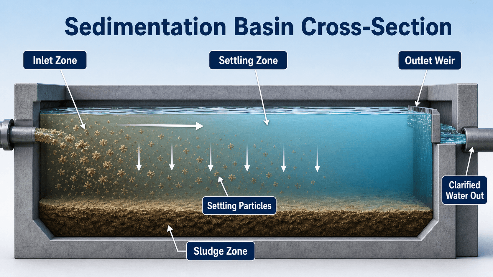
The most important idea is controlled velocity. Water must move slowly and evenly enough for particles to settle without being swept directly to the outlet.
What is a Sedimentation Basin?
A sedimentation basin, also called a settling basin or clarification basin, is a tank or basin designed to remove particles from water by gravity settling. In water treatment plants, the particles of interest are usually floc particles formed during upstream chemical treatment, along with suspended sediment that is heavy enough to settle under controlled flow conditions.
The basin is not just a large open tank. It is a hydraulic treatment unit with an inlet zone, settling zone, sludge zone, outlet zone, and sludge removal system. If any one of these parts performs poorly, water may short-circuit through the basin, settled solids may resuspend, or floc may carry over into the filters.
Sedimentation is not intended to produce finished drinking water by itself. Its job is to remove the largest practical fraction of settleable particles so downstream filters can polish the smaller particles that remain.
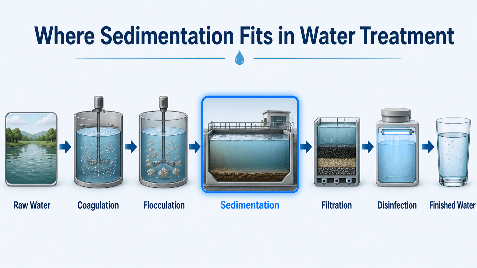
Where Sedimentation Fits in Water Treatment
In a conventional surface water treatment plant, sedimentation works as part of a treatment train. Coagulation destabilizes fine particles, flocculation gently grows those particles into larger floc, sedimentation removes much of that floc by settling, and filtration removes smaller particles that do not settle.
This sequence matters because a sedimentation basin depends heavily on upstream chemistry and mixing. A basin with good geometry can still perform poorly if the coagulant dose is wrong, the floc is too small, the pH is outside the useful range, or flocculation mixing breaks particles apart.
For a broader view of the full treatment sequence, see Water Treatment Processes. For the two upstream steps that prepare particles for settling, see Coagulation in Water Treatment and Flocculation in Water Treatment.
Main Components of a Sedimentation Basin
A sedimentation basin is usually divided into functional regions. These regions are not just labels on a diagram; they control how water enters, how particles settle, where sludge accumulates, and how clarified water leaves the basin.
| Component | Primary function | What can go wrong |
|---|---|---|
| Inlet zone | Dissipates incoming energy and distributes flow evenly | Jets, turbulence, and uneven flow can create short-circuiting |
| Settling zone | Provides quiet hydraulic conditions for floc particles to settle | High velocity, density currents, or poor flow distribution can reduce effective settling |
| Sludge zone | Stores settled solids until they are removed | Excess sludge can reduce volume, turn septic, or resuspend into the water column |
| Outlet weirs and launders | Collect clarified water uniformly from the basin surface | Uneven weir loading can pull solids toward localized outlet areas |
| Baffles | Improve flow distribution and reduce short-circuiting | Damaged, missing, or poorly placed baffles can create dead zones or high-velocity paths |
| Sludge collection system | Moves settled solids to hoppers or removal points | Collector failure can cause sludge buildup and solids carryover |
How a Sedimentation Basin Works
A sedimentation basin works by reducing water velocity and creating enough hydraulic residence time for particles to fall out of suspension. The flow should enter smoothly, spread across the basin, move through the settling zone, and exit evenly over outlet weirs without disturbing the sludge layer at the bottom.
Gravity settling
The basic mechanism is gravity. A particle settles when its downward settling velocity is sufficient for it to reach the sludge zone before the horizontal flow carries it to the outlet. Larger, denser floc particles settle more easily than small colloidal particles.
Floc behavior
Floc must be large enough to settle but strong enough to survive the transition from flocculation into sedimentation. If the basin inlet is too turbulent, floc can break apart and behave like smaller particles that remain suspended.
Clarified water collection
Clarified water leaves through outlet weirs, launders, or collection channels. The outlet should draw water evenly so the basin does not develop a preferred path that bypasses the intended settling volume.
Sludge removal
Settled solids accumulate in the sludge zone and must be removed on a controlled schedule. Sludge removal may use hoppers, mechanical scrapers, vacuum systems, blowdown lines, or pumps depending on the basin layout.
What Sedimentation Removes and What It Does Not
Sedimentation is most effective for particles that can settle within the available basin area and detention time. It is much less effective for dissolved substances or fine colloids that have not been destabilized and grown into settleable floc.
| Water quality item | How sedimentation affects it | Engineering note |
|---|---|---|
| Floc particles | Usually removed well when upstream coagulation and flocculation are effective | This is one of the main purposes of the basin |
| Settleable suspended solids | Removed by gravity settling | Removal depends on particle size, density, flow rate, and basin hydraulics |
| Turbidity | Reduced when turbidity is associated with settleable particles or floc | Remaining turbidity is handled by filtration and other treatment barriers |
| Dissolved chemicals | Not reliably removed by sedimentation alone | Requires chemical treatment, adsorption, membranes, oxidation, ion exchange, or other processes depending on the contaminant |
| Very fine colloids | Poorly removed unless they are destabilized and attached to larger floc | Coagulation control is critical |
| Microorganisms | Some particle-associated organisms may settle, but sedimentation is not the final pathogen barrier | Filtration and disinfection remain essential |
If a contaminant is dissolved rather than particle-bound, a sedimentation basin should not be expected to remove it just because the water looks clearer.
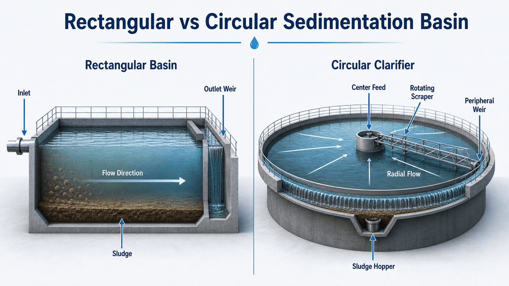
Rectangular vs Circular Sedimentation Basins
Sedimentation basins are commonly arranged as rectangular horizontal-flow basins or circular clarifiers. The best choice depends on available footprint, hydraulic layout, sludge collection needs, construction constraints, redundancy, and the type of treatment plant.
| Basin type | How flow moves | Typical advantages | Practical concerns |
|---|---|---|---|
| Rectangular sedimentation basin | Horizontal flow from inlet end to outlet end | Fits well in parallel treatment trains and can be arranged efficiently in long basins | Needs careful inlet distribution, baffles, and sludge collection along the basin floor |
| Circular clarifier | Radial flow from center feed or peripheral feed | Works well with rotating sludge scrapers and continuous sludge collection | Can be sensitive to center-feed energy, density currents, and uneven peripheral weir flow |
| Plate or tube settler basin | Flow passes through inclined plates or tubes | Increases effective settling area in a smaller footprint | Requires attention to clogging, solids loading, cleaning access, and flow distribution |
Sedimentation Basin vs Clarifier vs Settling Tank
The terms sedimentation basin, settling tank, and clarifier are often used together, but they emphasize slightly different parts of the same treatment idea. Understanding the difference helps avoid confusion when reading design manuals, plant drawings, and operations documents.
| Term | What it emphasizes | Typical use |
|---|---|---|
| Sedimentation basin | The gravity settling process and basin where particles settle | Common in drinking water treatment and general water treatment education |
| Settling tank | The physical tank used for settling | General term used in water, wastewater, and industrial treatment |
| Clarifier | The production of clarified water and collection of settled solids | Common for circular tanks, mechanically equipped basins, and wastewater applications |
| Primary clarifier | Removal of settleable solids near the beginning of wastewater treatment | More wastewater-focused than conventional drinking water sedimentation |
For this page, the focus is on sedimentation basins used in water treatment plants. The same gravity-settling principles also appear in wastewater clarifiers, stormwater sediment basins, and industrial settling tanks, but the design objectives and solids characteristics can be different.
Key Design and Operating Factors
Sedimentation basin performance is controlled by hydraulic loading, particle settling behavior, basin geometry, flow distribution, and sludge handling. A basin that looks large enough by volume alone may still perform poorly if the flow pattern is uneven or the outlet pulls too much water from one area.
| Factor | Why it matters | Engineering implication |
|---|---|---|
| Surface overflow rate | Compares plant flow to basin surface area | High overflow rate can carry particles out before they settle |
| Detention time | Represents theoretical time water spends in the basin | Too little time reduces settling; too much unused volume may indicate dead zones or poor hydraulics |
| Floc quality | Large, dense, durable floc settles better than small or fragile floc | Upstream coagulation dose, pH, alkalinity, and flocculation energy must be controlled |
| Inlet and outlet hydraulics | Flow distribution controls whether the full basin volume is used | Baffles, inlet ports, launders, and weirs must limit jets and short-circuiting |
| Sludge removal | Settled solids must be removed before they reduce performance | Collectors and blowdown cycles should prevent sludge buildup and resuspension |
| Temperature and density effects | Cold water changes viscosity, and density currents can alter flow paths | Seasonal changes may require operational adjustments even when flow stays similar |
Useful Sedimentation Basin Equations
Two simple calculations help explain how sedimentation basins are commonly checked: surface overflow rate and theoretical detention time. They do not replace detailed design criteria, pilot testing, or regulatory requirements, but they help engineers and operators understand whether hydraulic loading is reasonable.
- Q Flow rate through the basin, commonly expressed as MGD, gal/day, ft³/s, m³/day, or L/s depending on the design context.
- As Plan surface area of the basin. For gravity settling, surface area is often more important than total depth once adequate sludge storage and hydraulics are provided.
- V Effective basin volume. Dead zones, short-circuiting, and sludge buildup can reduce the useful volume below the geometric volume.
Example: surface overflow rate
If a basin treats 2.0 MGD and has a plan surface area of 4,000 ft², the surface overflow rate is:
The result connects flow to available settling area. If plant flow increases but basin surface area stays the same, particles have less opportunity to settle before reaching the outlet.
Sedimentation Basin Review Checklist
A good basin review looks beyond concrete dimensions. Engineers should check whether the treatment train is producing settleable floc, whether the basin hydraulics use the available volume, and whether sludge is removed before it affects performance.
Start upstream with raw water turbidity, coagulant dose, pH, alkalinity, and floc formation. Then review basin hydraulics, surface overflow rate, detention time, baffle condition, outlet weir balance, sludge depth, and filter performance. If filters are loading quickly, the sedimentation basin may be passing floc even if the outlet water looks visually clear.
| Check or decision | What to look for | Why it matters |
|---|---|---|
| Confirm upstream floc quality | Large, dense floc leaving flocculation without being broken apart | Weak floc cannot be fixed by basin volume alone |
| Review inlet distribution | No strong jetting, visible turbulence, or uneven flow path | Jets can short-circuit the basin and carry solids toward the outlet |
| Check outlet weirs | Even water level and uniform overflow across the collection system | Uneven weir loading can create localized high velocities and solids carryover |
| Track sludge depth | Sludge blanket level, hopper accumulation, and collector operation | Excessive sludge reduces volume and increases resuspension risk |
| Compare filter response | Filter headloss, backwash frequency, and turbidity trends after sedimentation | Filters often reveal sedimentation problems before the basin looks obviously overloaded |
Engineering Judgment and Field Reality
Textbook diagrams show smooth horizontal flow and uniform particle settling, but real basins are affected by density currents, wind, temperature changes, poor baffle conditions, uneven sludge withdrawal, and operational changes upstream. The basin may also behave differently during storm-driven turbidity spikes, algae events, cold water periods, or rapid flow changes.
Field review should look for trends, not just single readings. Rising settled-water turbidity, shorter filter runs, uneven weir flow, sludge near the outlet, or visible floc carryover can indicate that the basin is no longer providing the expected barrier before filtration.
A sedimentation basin can meet a theoretical detention time and still perform poorly if short-circuiting reduces the effective volume. Hydraulic behavior often matters as much as basin size.
When This Breaks Down
Sedimentation breaks down when particles do not settle fast enough, when the basin does not use its full volume, or when previously settled solids are disturbed. The cause may be hydraulic, chemical, mechanical, or operational.
- Short-circuiting: water takes a faster path from inlet to outlet, reducing the true settling time.
- Fragile floc: particles form but break apart before or during sedimentation.
- Hydraulic overload: high flow increases surface overflow rate and reduces particle removal.
- Sludge resuspension: settled material is lifted back into the water column by velocity, sludge blanket buildup, or collector problems.
- Density currents: temperature or solids concentration differences create flow layers that bypass the intended settling pattern.
- Algae or floating solids: floating material can pass over weirs if surface removal and upstream control are not adequate.
Common Mistakes and Practical Checks
The most common mistake is treating sedimentation as a standalone tank problem. In actual water treatment operation, the basin is part of a controlled process that depends on upstream chemistry, mixing, hydraulic loading, residuals handling, and downstream filter feedback.
- Ignoring coagulation: small colloids may not settle unless they are first destabilized and grown into floc.
- Checking only detention time: detention time does not prove that flow is evenly distributed.
- Letting sludge accumulate too long: sludge buildup can reduce active volume and increase carryover risk.
- Overlooking weir loading: an uneven outlet can undo otherwise good settling conditions.
- Confusing visual clarity with stable operation: short-term clarity can hide filter loading problems or seasonal process drift.
Do not diagnose high filter headloss as a filter-only problem until settled-water turbidity, floc carryover, basin hydraulics, and sludge removal have been reviewed.
Useful References and Design Context
Sedimentation basin design and operation should be checked against project-specific design criteria, regulatory expectations, and utility operating procedures. Public technical manuals are useful for understanding how sedimentation and clarification support downstream filtration.
- Oregon Health Authority sedimentation guidance: Sedimentation and Clarification guidance for drinking water treatment explains sedimentation as a gravity-based process for removing particulates and improving filtration performance.
- Project-specific criteria: Plant flow, raw water quality, owner standards, state or local requirements, redundancy needs, residuals handling, and filter performance targets can all control final design and operating decisions.
- Engineering use: Engineers use references like this to frame process intent, then apply site-specific calculations, pilot testing, jar testing, historical turbidity data, and operational feedback.
Frequently Asked Questions
A sedimentation basin is a treatment structure that slows water so suspended solids and floc particles can settle by gravity. In a conventional water treatment plant, it is commonly located after coagulation and flocculation and before filtration.
The purpose of a sedimentation basin is to remove settleable particles before filtration. By reducing suspended solids and turbidity, it lowers the load on downstream filters and helps the plant maintain more stable finished water quality.
The terms are closely related. Sedimentation describes the gravity-settling process, while clarification describes the production of clearer water. A clarifier is often the basin or tank where sedimentation and sludge collection occur.
Poor performance is commonly caused by weak coagulation, fragile floc, excessive flow, short-circuiting, uneven inlet or outlet hydraulics, sludge buildup, or sludge resuspension. Sedimentation performance should always be checked with upstream mixing and downstream filter loading.
Summary and Next Steps
A sedimentation basin is a gravity-settling unit that removes floc and suspended solids before filtration. Its value comes from reducing turbidity, controlling solids loading, and giving downstream filters a cleaner, more stable flow to polish.
Good sedimentation depends on more than basin size. Engineers should review flow distribution, surface overflow rate, detention time, floc quality, outlet weir balance, sludge removal, seasonal effects, and filter response before deciding whether the basin is performing well.
Where to go next
Continue your learning path with related Turn2Engineering resources.
-
Coagulation in Water Treatment
Learn how chemical destabilization prepares fine particles so they can form larger floc and eventually settle.
-
Flocculation in Water Treatment
Learn how gentle mixing grows destabilized particles into settleable floc before sedimentation.
-
Water Treatment Processes
See how sedimentation fits into the larger treatment train with filtration, disinfection, chemical treatment, and advanced processes.