Key Takeaways
- Definition: Landslide mitigation is the set of geotechnical measures used to reduce slope movement risk by lowering driving forces or increasing resisting forces.
- Use case: It is used when natural or constructed slopes threaten roads, buildings, utilities, retaining systems, or long-term site stability.
- Main decision: The most important choice is matching the mitigation method to the failure mechanism, groundwater regime, and construction constraints.
- Outcome: A good mitigation strategy improves stability, manages water, limits erosion, and remains buildable and maintainable over the life of the project.
Table of Contents
Introduction
In brief: Landslide mitigation reduces slope failure risk by controlling water, reshaping slopes, reinforcing soil or rock, and protecting the ground surface from deterioration.
Who it’s for: Students, FE/PE prep, and designers.
For informational purposes only. See Terms and Conditions.
In practice, slope stabilization is rarely one fix. The best landslide mitigation systems are selected after understanding how the slope is moving, why it is moving, and what project limits control the design.
Landslide Mitigation infographic
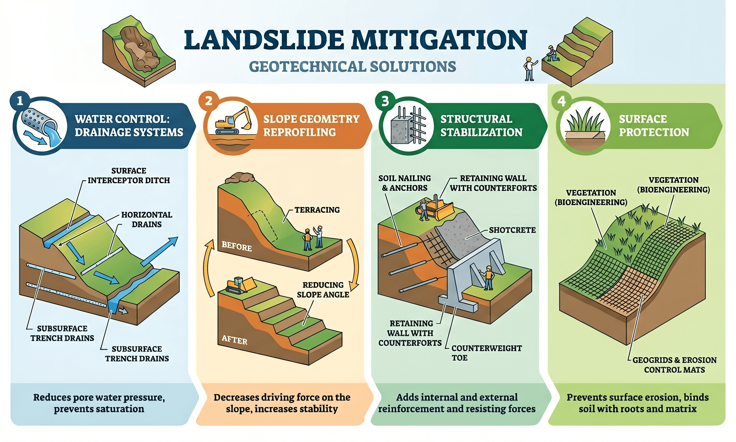
Notice that each method changes the stability problem differently. Drainage reduces pore pressure, regrading lowers driving forces, structural systems add resistance, and vegetation or erosion control preserves the slope surface so small problems do not grow into larger failures.
What is landslide mitigation?
Landslide mitigation is the engineering process of reducing the probability or consequence of slope movement. The term covers both temporary and permanent measures used on natural hillsides, excavated cuts, embankments, retaining systems, and developed sites. The objective is not just to “stop dirt from moving.” It is to understand the failure mechanism and then alter the conditions that made the slope unstable in the first place.
In geotechnical terms, slope movement occurs when the forces driving soil or rock downslope exceed the forces resisting that movement. Those driving forces can increase because of rainfall infiltration, rising groundwater, surcharge loading, toe erosion, construction disturbance, seismic shaking, or unfavorable stratigraphy. Resisting forces depend on shear strength, effective stress, reinforcement, geometry, and drainage performance.
That is why good landslide mitigation usually starts with diagnosis, not immediate construction. A retaining wall may look like the answer, but if perched water is the real trigger, drainage may provide more benefit for less cost. Likewise, adding vegetation may improve a shallow erosion problem but do little for a deep rotational slide. The engineering value comes from matching the measure to the mechanism.
Core principles, variables, and units
Most landslide mitigation decisions can be traced back to a small number of physical controls: slope angle, soil or rock strength, groundwater conditions, unit weight, loading, and geometry of the potential slip surface. Engineers use both field evidence and calculations to determine which variables matter most on a given site.
Key variables and typical ranges
Early screening should focus on whether the slope problem is shallow or deep, rapid or slow, soil-controlled or water-controlled, and localized or system-wide. Numbers matter, but they only help after the movement mechanism is identified correctly.
- β Slope angle, commonly expressed in degrees or as H:V ratio; steeper slopes generally have higher driving forces.
- c′ Effective cohesion, usually in psf, kPa, or ksi-equivalent context for rock interfaces; sensitive to soil type, weathering, and sampling disturbance.
- φ′ Effective friction angle in degrees; often one of the most important shear strength inputs for granular soils and many residual soil conditions.
- u Pore water pressure, usually in psf or kPa; rising pore pressure can sharply reduce available shear resistance.
- γ Unit weight of soil or rock mass, commonly pcf or kN/m³; heavier saturated materials increase driving forces.
- FS Factor of safety, the ratio of resisting to driving effects; used as a screening and design metric, not as a substitute for field judgment.
If the slope condition changes dramatically after storms, assume groundwater and surface water deserve immediate attention before jumping to heavy structural measures.
Practical unit handling matters here. Geotechnical slope work often mixes US customary and SI references, especially when reading agency manuals, vendor data, and academic papers. Keep unit systems consistent from soil parameters to reinforcement loads. A correct concept with mixed units can still produce a completely wrong design.
Decision logic and mitigation workflow
Landslide mitigation design is usually a sequence of questions. What is moving? How deep is it moving? What role is water playing? What can actually be built on the site? The strongest solutions often combine more than one mitigation family.
1) Identify the failure mode and likely slip geometry. 2) Confirm groundwater and drainage conditions. 3) Decide whether to reduce driving force, increase resistance, or both. 4) Screen feasible methods based on access, cost, constructability, and maintenance. 5) Check short-term and long-term stability, including staged construction effects.
Four mitigation families dominate most projects. Drainage control includes interceptor ditches, horizontal drains, trench drains, subsurface collection, and outlet protection. Slope geometry modification includes flattening, benching, unloading the crest, or buttressing at the toe. Structural stabilization includes soil nails, anchors, retaining walls, piles, micropiles, shotcrete facings, and reinforced earth systems. Surface protection includes vegetation, erosion control blankets, geosynthetics, riprap, and bioengineering measures.
The right combination depends on the site. A highway cut in residual soil may respond well to drains plus regrading. A constrained urban slope with no room to flatten may require anchors or piles. A fill slope suffering from shallow sloughing may only need drainage and erosion protection if the deeper mass is stable.
Equations and calculations
Landslide mitigation design is often checked through slope stability analysis. While the exact method may involve limit equilibrium software or numerical modeling, the core concept is still a resisting-versus-driving comparison.
In plain language, the factor of safety tells you how much available resistance the slope has relative to the demand causing it to fail. A mitigation measure works by increasing the numerator, decreasing the denominator, or doing both.
This Mohr-Coulomb relationship is the backbone of many soil slope stability evaluations. Here, \( \tau_f \) is available shear strength, \( c’ \) is effective cohesion, \( \sigma’ \) is effective normal stress, and \( \phi’ \) is the effective friction angle. Drainage matters because increasing pore pressure lowers effective stress, which reduces available resistance.
Engineers should be careful not to treat these equations as standalone answers. Soil parameters may vary by depth, season, weathering profile, and sampling method. Residual strengths may control reactivated slides even when peak strengths look favorable in the lab. That is why the inputs usually matter more than the algebra.
Worked example
Example
Consider a roadway cut slope that has shown shallow failures after major rain events. Site reconnaissance identifies wet zones, raveling near the face, and seepage at mid-height. Laboratory testing suggests the soil is moderately plastic with reduced strength when saturated. Because failures are shallow and storm-triggered, the first mitigation screen points toward drainage and surface protection rather than deep foundations or a large retaining wall.
The engineer proposes a package of crest diversion, lined interceptor drainage, horizontal drains in the wettest zones, local flattening of the steepest portion of the face, and an erosion-control/vegetation system. The logic is straightforward: reduce infiltration, lower pore pressure, decrease surface runoff damage, and modestly reduce the local slope angle. If analysis shows these measures raise the slope to an acceptable margin of stability, the project avoids a more expensive structural solution.
The same site could require a different answer if the movement were deeper, if the toe were being eroded by a channel, or if right-of-way prevented flattening. In that case, toe buttressing, soldier piles, anchors, or another structural system might become the governing option. The worked example shows the most important principle in landslide mitigation: do not design the fix before understanding the failure mode.
Engineering judgment and field reality
Field conditions often change the design far more than office calculations suggest. Slopes are rarely uniform. They contain old scarps, buried organics, slickensides, fill pockets, root paths, seepage lenses, utility leaks, and construction disturbance that are not obvious in a simplified model. A beautiful stability analysis based on poor subsurface understanding can still lead to the wrong mitigation plan.
Groundwater is one of the biggest real-world disruptors. Slopes that appear dry during a site visit may become critically wet after prolonged rainfall or seasonal recharge. Outlet maintenance is another common failure point. Subdrains and interceptor systems only help when they stay open, protected, and properly discharged.
Many “failed stabilization” projects are actually drainage failures, maintenance failures, or site characterization failures rather than proof that the chosen mitigation family was inherently wrong.
Experienced engineers also pay close attention to constructability. A system that works perfectly in theory may be unrealistic if drill rigs cannot access the site, outlets cannot be protected, excavation would destabilize adjacent property, or utilities prevent wall installation. Landslide mitigation succeeds when the geotechnical concept, the field logistics, and the maintenance plan all align.
When this breaks down
Landslide mitigation design becomes less reliable when the failure mechanism is misidentified, when groundwater conditions are poorly constrained, or when soil parameters are overly optimistic. Surface-only measures break down when the problem is deep-seated. Crest drainage can help, but it will not solve a slide driven by weak basal layers several tens of feet below grade. Likewise, vegetation and erosion control can preserve a slope face yet do little for an active rotational failure with a deep slip surface.
The method also breaks down when mitigation is selected around budget or appearance instead of mechanics. For example, a decorative retaining wall near the slope toe may provide little global stability benefit if the critical surface passes well below or behind it. Similarly, anchors and nails may underperform if corrosion, drainage, or bond-zone assumptions are not handled properly.
Another breakdown condition occurs during staged construction. Excavation, unloading, temporary drainage interruptions, or delayed facing installation can lower short-term stability even if the final condition looks acceptable. In slope work, the temporary condition can govern.
Common pitfalls and engineering checks
- Assuming all slope movement is shallow when the site may have a deeper composite or rotational failure surface.
- Ignoring groundwater seasonality and designing from a single dry-weather site visit.
- Using peak laboratory strengths for a slope that is likely controlled by softened or residual conditions.
- Adding reinforcement without verifying that water management and outlet details will remain functional.
- Overlooking erosion at the toe, which can slowly remove support and reactivate movement.
- Failing to check maintenance access for drains, ditches, and outlet structures.
The most expensive mistake is choosing a mitigation measure that treats the visible symptom while leaving the actual slide trigger in place.
| Mitigation family | Main effect | Typical use | Engineering check |
|---|---|---|---|
| Drainage | Reduces pore pressure and infiltration | Wet slopes, storm-triggered instability, seepage zones | Confirm outlets, clogging risk, and long-term maintenance |
| Regrading / unloading | Reduces driving force | Where space exists for flatter slopes or benches | Check right-of-way, erosion risk, and temporary stability |
| Structural reinforcement | Increases resisting force | Constrained sites, deeper failures, critical infrastructure | Verify load path, durability, drainage, and access for installation |
| Surface protection | Limits erosion and shallow deterioration | Shallow surficial movement and slope face protection | Do not rely on it alone for deep global instability |
Always ask whether the selected measure addresses the controlling failure surface, the controlling groundwater condition, and the controlling construction stage.
Visualizing landslide mitigation in practice
A useful mental model is to picture a slope cross-section and ask four simple questions. Where is water entering? Where is the likely slip surface? What part of the slope can be reshaped? Where can resistance be added if geometry alone is not enough? Thinking through the slope this way helps prevent random method selection.
For shallow failures, the visual focus is often the upper face, runoff patterns, and vegetation cover. For deeper failures, the visual focus shifts to slip geometry, toe support, stratigraphy, groundwater levels, and reinforcement load paths. The more the mitigation concept can be tied to the actual failure sketch, the stronger the design usually becomes.
This section remains text-only because the main infographic already covers the primary mitigation families clearly.
Relevant standards and design references
Landslide mitigation design is usually governed by a mix of geotechnical references, agency manuals, material standards, and project-specific requirements rather than a single universal code.
- FHWA geotechnical engineering circulars and slope manuals: Commonly used for roadway slope stability, reinforced systems, and geotechnical mitigation selection in transportation work.
- USACE engineering manuals: Valuable for slope stability, drainage, embankments, and earth structures where federal or dam-related guidance is relevant.
- ASTM soil and rock testing standards: Used to establish classification, index properties, strength, density, permeability, and other parameters needed for design inputs.
- AASHTO or DOT geotechnical manuals: Often govern highway cut slopes, embankments, retaining systems, and acceptable factors of safety for transportation projects.
- Project geotechnical report and local authority criteria: These frequently control allowable methods, drainage discharge requirements, maintenance expectations, and construction staging limits.
The key design lesson is that mitigation details must match the standards actually governing the owner and project type. Highway slopes, dam embankments, and private developments may all use different acceptance criteria even when the soil behavior is similar.
Frequently asked questions
There is rarely one best method because different slopes fail for different reasons. The most effective landslide mitigation plan is the one that directly addresses the controlling mechanism, which often means combining drainage, geometry changes, reinforcement, and surface protection rather than relying on a single treatment.
Drainage improves slope stability by reducing infiltration and lowering pore water pressure, which usually increases effective stress and available shear resistance. It is often the highest-value mitigation measure when the slope problem gets worse after rainfall or seepage is visible.
Structural systems are usually needed when the site has limited room to flatten the slope, when the movement is too deep for surface fixes, or when nearby roads, buildings, utilities, or property lines prevent large earthwork changes.
Vegetation can be very useful for erosion control, shallow surficial stability, and runoff management, but it is usually not enough for deep-seated or actively moving landslides where global stability is the real concern.
Landslide mitigation is common in highway cuts, rail corridors, residential developments, dams, pipelines, hillside retaining systems, and any project where slope movement threatens life safety, serviceability, access, or long-term asset performance.
Summary and next steps
Landslide mitigation is fundamentally about changing the slope system so movement is less likely. That may mean reducing water, flattening geometry, unloading the crest, buttressing the toe, reinforcing the soil or rock mass, or protecting the surface from erosion and infiltration. The right answer depends on the failure mechanism, not just the visible damage.
For most real projects, the best workflow is: identify the slide type, define groundwater conditions, screen feasible methods, check global and local stability, and then confirm the solution can actually be built and maintained. The strongest designs are usually the ones that treat both water and mechanics instead of focusing on only one side of the problem.
If you are studying this topic, focus on how each mitigation family changes either the driving forces or the resisting forces. If you are applying it in design, focus on field evidence, parameter selection, staging, drainage reliability, and whether the chosen measure truly intersects the controlling failure surface.
Where to go next
Continue your learning path with these curated next steps.
-
Read a deeper dive on slope stability
This is the natural next topic if you want to understand how slopes are analyzed before mitigation options are selected.
-
Review soil mechanics fundamentals
A stronger grasp of effective stress, seepage, shear strength, and soil behavior makes landslide mitigation decisions much clearer.
-
Explore related equation pages
Use formula-focused resources to reinforce factor of safety, shear strength, and other geotechnical relationships that support this topic.