Key Takeaways
- Core idea: A steel frame structure uses steel beams, columns, braces, and connections as the main skeleton that carries building loads to the foundation.
- Engineering use: Steel frames are common in offices, high-rise buildings, warehouses, industrial facilities, long-span roofs, and structures that need flexible open space.
- What controls it: Member strength, frame stability, lateral drift, connection behavior, fire protection, corrosion exposure, and constructability often control the final design.
- Practical check: A steel frame is only as reliable as its complete load path, including diaphragms, collectors, braces, connections, base plates, anchors, and foundations.
Table of Contents
Introduction
Steel frame structures are building systems where steel beams, columns, braces, and connections form the primary load-carrying skeleton. Floors and roofs transfer gravity loads into beams and columns, while wind and seismic forces are resisted by braced frames, moment frames, diaphragms, cores, or other lateral systems before reaching the foundation.
How Steel Frame Structures Work
Notice that the steel skeleton is not just a collection of strong members. The important engineering idea is continuity: each load needs a reliable path through framing, connections, base plates, anchors, foundations, and supporting soil.
What Is a Steel Frame Structure?
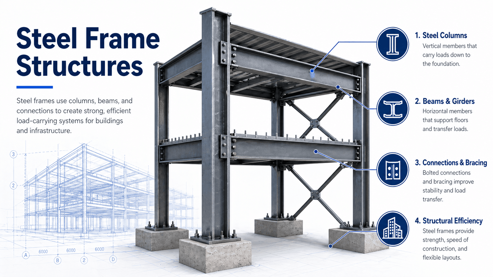
A steel frame structure is a structural system in which steel members carry the main building loads. Vertical columns support compression forces, beams and girders span between supports, braces stabilize the frame against sideways movement, and connections transfer force from one element to the next.
In structural engineering, the frame is usually separated into two related systems: the gravity system and the lateral system. The gravity system supports floors, roofs, equipment, walls, and occupancy loads. The lateral system controls wind pressure, seismic shaking, diaphragm forces, drift, overturning, and stability. A good steel frame design makes both systems visible, continuous, and buildable.
Main Components of Steel Frame Structures
Steel-framed buildings are assembled from primary and secondary members. The exact arrangement depends on the building height, span, occupancy, architectural layout, site exposure, and design loads, but most steel frames use a similar set of structural parts.
| Component | Main role | Engineering note |
|---|---|---|
| Columns | Carry vertical load and sometimes lateral frame forces. | Column buckling, effective length, base fixity, and combined axial-bending effects are important design checks. |
| Beams and girders | Support floors, roofs, decks, walls, and secondary framing. | Flexure, shear, deflection, vibration, and lateral-torsional buckling can control member selection. |
| Bracing | Provides lateral stiffness and transfers wind or seismic forces. | Braces usually work through axial tension and compression, so connection detailing and load reversal matter. |
| Connections | Transfer shear, axial force, moment, or a combination of forces. | Bolted and welded connections often control constructability, cost, tolerance, and real frame behavior. |
| Decks and diaphragms | Collect floor or roof loads and distribute lateral forces to resisting elements. | Diaphragm attachment, collector forces, openings, and edge detailing are easy to miss in simplified diagrams. |
| Base plates and anchors | Transfer column loads into foundations. | Anchor rod layout, grout, bearing pressure, shear transfer, and erection tolerances need coordination with foundation design. |
How Loads Move Through a Steel Frame
The best way to understand steel frame structures is to trace the load path. Every load entering the building must travel through connected elements until it reaches stable support. If the path is interrupted, the problem may not appear as a weak beam; it may appear as drift, connection distress, diaphragm damage, foundation overstress, or instability.
Gravity Load Path
Gravity loads usually begin at the floor or roof surface. The load moves through metal deck, concrete slab, joists, beams, girders, columns, base plates, anchor rods, foundations, and finally soil or rock. For a deeper foundation-level view, see load path analysis.
Lateral Load Path
Wind and seismic loads often enter through the cladding or building mass, move into roof and floor diaphragms, pass through collectors or drag struts, and then enter braced frames, moment frames, shear walls, cores, or foundation elements. This is why wind design, seismic behavior, diaphragm design, and steel connection detailing must be coordinated early.
Before sizing individual members, trace where the gravity loads and lateral loads enter the frame, which members collect them, which connections transfer them, and how the forces reach the foundation.
Types of Steel Frame Structures
“Steel frame” can describe several different structural systems. The frame type affects member sizes, drift control, connection cost, architectural flexibility, construction sequence, and how the building behaves under wind or seismic loading.
| Frame type | How it works | Best fit | Main limitation |
|---|---|---|---|
| Braced steel frame | Diagonal braces resist lateral loads through axial tension and compression. | Efficient lateral resistance in many low-rise, mid-rise, and industrial buildings. | Bracing can conflict with windows, doors, corridors, equipment, and open architectural bays. |
| Moment-resisting frame | Rigid beam-column connections resist lateral loads through bending and frame action. | Open floor plans, façades, entrances, and locations where diagonal bracing is undesirable. | Usually requires heavier members, stiffer connections, and careful drift control. |
| Portal frame | Columns and rafters form a rigid frame, often with haunches near the eaves. | Warehouses, industrial buildings, agricultural structures, and long-span single-story buildings. | Frame geometry, foundation restraint, roof slope, and lateral bracing strongly affect behavior. |
| Steel truss frame | Triangulated members carry loads mainly through axial forces. | Long-span roofs, bridges, arenas, hangars, and transfer structures. | Connection detailing, fabrication labor, member buckling, and erection sequencing can be significant. |
| Composite steel frame | Steel beams work together with concrete slabs using shear connectors. | Multi-story buildings where floor stiffness, vibration performance, and efficient beam design matter. | Requires coordination of deck, slab, studs, fire ratings, openings, and construction-stage loading. |
What Controls Steel Frame Design?
Steel frame design is not controlled by strength alone. A member may have enough bending strength but still fail a deflection check, vibration check, drift limit, connection requirement, fire rating, or constructability constraint. The controlling issue changes by building type and frame layout.
| Design control | Why it matters | Engineering implication |
|---|---|---|
| Strength | Members and connections must resist axial force, shear, bending, torsion, and combined effects. | Shapes, grades, connection types, and load combinations are selected to satisfy required capacity. |
| Stability | Steel members can buckle locally, laterally, torsionally, or globally before material strength is reached. | Bracing, unbraced length, compactness, frame analysis, and second-order effects become critical. |
| Serviceability | Excessive deflection, vibration, or drift can damage finishes and affect occupant comfort. | Beam depth, frame stiffness, camber, diaphragm stiffness, and drift limits may control the design. |
| Connections | The connection determines how forces actually pass between members. | Simple shear connections, moment connections, brace gussets, welds, bolts, and tolerances must match the design model. |
| Fire protection | Steel is noncombustible, but strength and stiffness reduce at elevated temperatures. | Spray-applied fireproofing, intumescent coating, encasement, rated assemblies, and exposed steel decisions affect design. |
| Corrosion exposure | Moisture, chemicals, drainage, and exterior exposure can reduce durability. | Coatings, galvanizing, weathering steel, enclosure, inspection access, and maintenance strategy may be required. |
Analysis Approach for Steel Frame Structures
Steel frame analysis starts by idealizing the real building into members, supports, joints, diaphragms, load combinations, and boundary conditions. That model is then used to estimate reactions, axial forces, shear, moments, deflections, drift, stability effects, and connection demands. For the analysis foundation behind this process, review structural analysis.
This simple relationship captures the design logic behind steel framing. The engineer determines the force or deformation demand from structural loads, analysis, and load combinations, then checks it against member strength, connection capacity, stability limits, drift limits, deflection limits, vibration criteria, fire rating requirements, and durability expectations.
- P Axial force in columns, braces, truss members, and some connection elements.
- V Shear force in beams, girders, connections, diaphragms, and collectors.
- M Bending moment in beams, girders, moment frames, base plates, and rigid connections.
- Δ Deflection or drift, often governing serviceability even when strength is adequate.
Steel Frame Design Review Checklist
A practical steel frame review should move from system behavior to details. Start with the overall load path, then check lateral stability, member behavior, connection assumptions, and field constructability. This avoids the common mistake of approving strong individual members inside a weak or incomplete structural system.
Trace loads first → identify the gravity and lateral systems → confirm diaphragm and collector paths → check member forces and serviceability → review connections and base plates → coordinate fire, corrosion, openings, tolerances, and erection sequence.
| Check or decision | What to look for | Why it matters |
|---|---|---|
| Gravity system continuity | Deck to beams, beams to girders, girders to columns, columns to foundations. | Missing or unclear support paths can create unintended load redistribution and connection distress. |
| Lateral system clarity | Braced bays, moment frames, shear walls, cores, diaphragms, collectors, and anchorage. | Wind and seismic forces need a complete path, not just strong vertical members. |
| Member stability | Unbraced lengths, compression members, beam bracing, flange restraint, and local slenderness. | Steel can buckle before reaching yield strength, especially in compression and bending members. |
| Connection assumptions | Simple, partially restrained, or moment-resisting behavior matching the analysis model. | A model with rigid joints but details that behave as simple shear connections can underpredict drift and forces. |
| Constructability | Bolt access, weld access, crane picks, splice locations, temporary bracing, and erection tolerances. | Excellent calculations can still fail as a design package if the steel cannot be fabricated, erected, or inspected efficiently. |
Example: Load Path in a Steel-Framed Office Building
Consider a multi-story steel office building with composite floor deck, steel beams, interior columns, perimeter columns, and a braced core. The floor slab supports people, partitions, furniture, mechanical systems, and its own self-weight. Those loads move through the deck into beams, from beams into girders, from girders into columns, and from columns into base plates and foundations.
Gravity Load Interpretation
If a beam is removed, interrupted, or poorly connected, the issue is not limited to that single beam. Adjacent beams, slab spans, connections, and columns may receive load that the original design did not intend. That is why steel frame design is a system problem, not just a member sizing exercise.
Lateral Load Interpretation
When wind pushes on the building façade, the force is collected by floors and roof diaphragms. The diaphragm transfers force to collectors and braced frames or moment frames. Those lateral frames then deliver overturning, shear, and axial forces into the foundations. If collectors, brace connections, or diaphragm attachments are not coordinated, the lateral system can be incomplete even if the visible bracing looks strong.
Engineering Judgment and Field Reality
Real steel frames rarely behave exactly like clean textbook diagrams. Construction sequence, temporary bracing, base plate leveling, anchor rod placement, weld access, slotted holes, connection tolerance, floor openings, and field modifications can change how forces move through the frame. A practical engineer checks both the idealized analysis model and the physical buildability of the details.
Many steel frame problems show up at the interfaces: brace gusset plates, beam-column connections, base plates, embed plates, deck edges, and anchor rods. These details decide whether the calculated load path can actually be built in the field.
When This Breaks Down
A simplified steel frame explanation breaks down when the frame is treated as only beams and columns. The real structure also includes stiffness assumptions, connection behavior, lateral force-resisting systems, construction-stage stability, fire resistance, corrosion exposure, and foundation interaction.
- Connections do not match the analysis model: assuming rigid frame behavior while detailing simple shear connections can create unexpected drift and redistribution.
- Diaphragms and collectors are ignored: lateral loads cannot reach braced frames or moment frames without a continuous horizontal force path.
- Temporary construction conditions are overlooked: incomplete frames may need temporary bracing before the permanent system is fully engaged.
- Serviceability is treated as secondary: vibration, deflection, and drift can control occupant comfort and façade performance even when strength checks pass.
Common Mistakes and Practical Checks
The most common steel frame mistakes come from oversimplifying how the system works. A strong column, deep beam, or large brace does not guarantee a strong building unless loads can move through the entire system without unintended weak links.
- Ignoring lateral-torsional buckling: beams need adequate compression flange restraint or sufficient unbraced strength.
- Confusing bracing with stability: visible diagonal members may not stabilize every required member or load case.
- Overlooking base details: base plates, anchor rods, grout, shear lugs, and foundation reinforcement must be coordinated with column reactions.
- Forgetting fireproofing weight and clearances: fire protection affects load, member dimensions, detailing, and architectural coordination.
- Treating corrosion as a coating-only issue: drainage, exposure, trapped moisture, inspection access, and maintenance planning also matter.
Do not evaluate steel frame structures only by member size. Confirm the load path, lateral system, bracing assumptions, connection behavior, serviceability limits, and foundation transfer before judging whether the frame is appropriate.
Relevant Steel Frame Design References
Steel frame structures are designed using project-specific drawings, building codes, load standards, material specifications, and structural steel design references. The references below are commonly used in U.S. structural steel building work.
- ANSI/AISC 360, Specification for Structural Steel Buildings: Provides requirements for structural steel member design, stability, connections, composite construction, and both LRFD and ASD design approaches.
- AISC Steel Construction Manual: Provides shape properties, design aids, connection guidance, and practical information used by steel designers and detailers.
- ASCE 7: Establishes minimum design loads such as dead, live, snow, rain, wind, seismic, and load combinations used before steel members are checked.
- AWS D1.1 Structural Welding Code—Steel: Covers welding requirements commonly referenced for structural steel fabrication and field welding.
- RCSC Specification for Structural Joints Using High-Strength Bolts: Provides requirements for high-strength bolted steel joints, including snug-tightened, pretensioned, and slip-critical connections.
Frequently Asked Questions
A steel frame structure is a building system where steel beams, columns, braces, connections, and foundations form the main load-carrying skeleton. The frame supports gravity loads from floors and roofs while a lateral system resists wind, seismic forces, and building drift.
The main parts are columns, beams, girders, bracing, connections, base plates, floor or roof deck, diaphragms, and foundations. Secondary members such as purlins, girts, joists, and edge angles may also support cladding, roofing, and floor systems.
A braced frame uses diagonal members to resist lateral forces mainly through axial tension and compression. A moment frame relies on rigid beam-column connections to resist lateral forces through bending, which can preserve open bays but usually requires heavier members and more demanding connection design.
Steel frames are widely used for large buildings because they provide high strength-to-weight ratio, long-span capability, fast erection, predictable fabrication, and flexible interior layouts. They are especially useful where open floor plans, tall columns, long roof spans, or future modification may be important.
Summary and Next Steps
Steel frame structures use beams, columns, braces, connections, diaphragms, and foundations to create a building skeleton that can carry gravity loads and resist lateral forces. The system is common in commercial, industrial, long-span, and multi-story construction because it combines strength, speed, flexibility, and predictable fabrication.
The key engineering idea is load path. A steel frame must be checked as a connected system, including member strength, stability, serviceability, connection behavior, diaphragm transfer, fire protection, corrosion exposure, constructability, and foundation anchorage.
Where to go next
Continue your learning path with related Turn2Engineering resources.
-
Steel Materials
Learn how steel grades, shapes, toughness, weldability, coatings, and material properties affect structural steel design.
-
Structural Loads
Understand the dead, live, wind, seismic, snow, rain, and construction loads that steel frames must resist.
-
Load Path Analysis
Build the system-level habit of tracing forces through members, connections, diaphragms, foundations, and soil.