Key Takeaways
- Definition: Hooke’s Law relates force and displacement in a linear spring or elastic member, usually written as \(F = kx\).
- Main use: Engineers use it to estimate spring force, deflection, stiffness, and first-pass elastic response during analysis, testing, and mechanical design.
- Watch for: It only works well while the system remains linear and elastic, with consistent units and a clearly defined sign convention.
- Outcome: After reading, you should be able to interpret the equation, solve for any main variable, and recognize when the model is too simple.
Table of Contents
Spring deformation and the linear force–displacement relationship
Hooke’s Law states that restoring force is proportional to displacement, making it the core equation for linear springs and small elastic deflections.
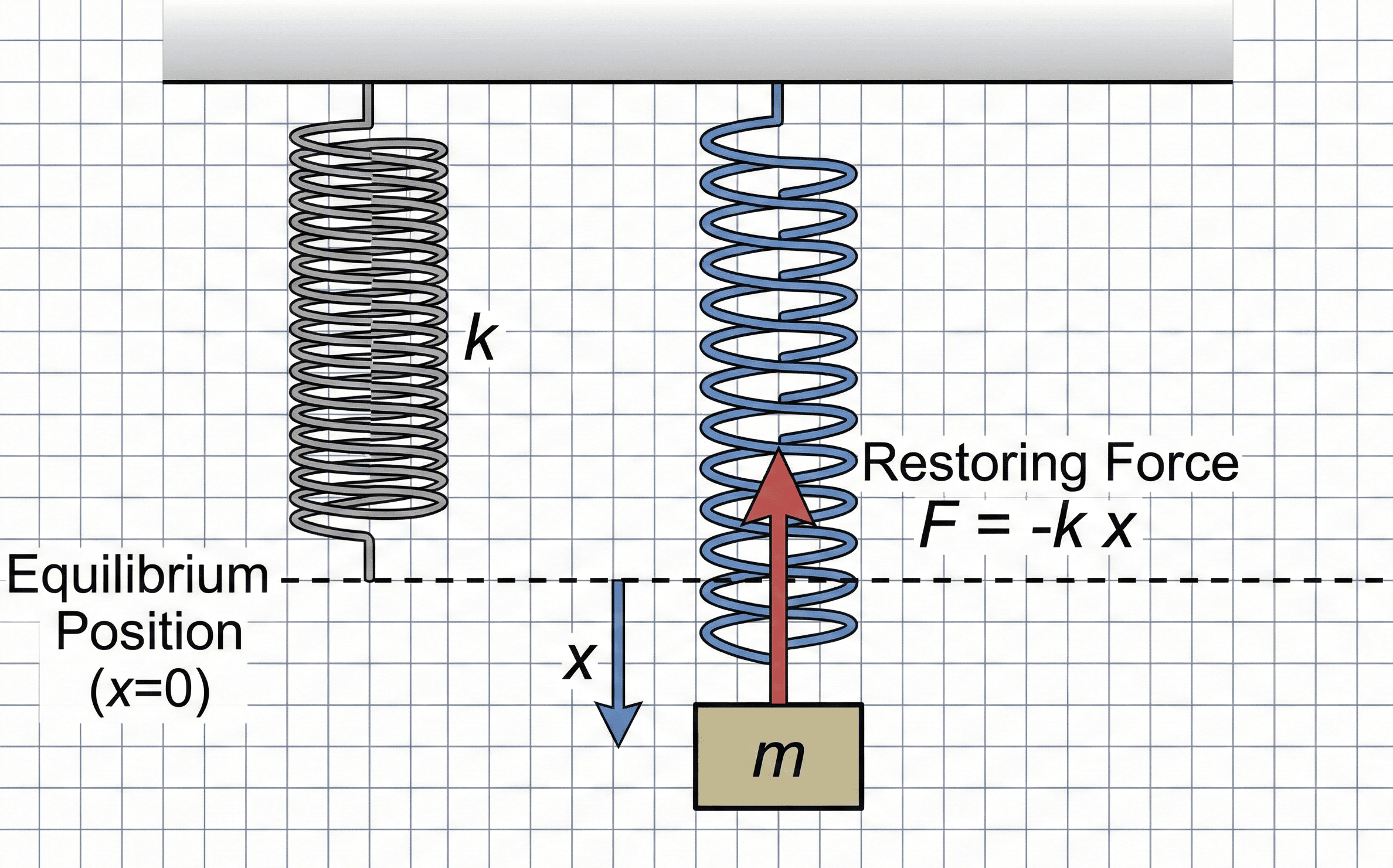
Notice the two ideas first: the displacement is measured from the original unloaded position, and the spring force grows in direct proportion to that displacement as long as behavior stays linear.
What is Hooke’s Law?
Hooke’s Law is one of the most important equations in mechanics because it describes how a spring or elastic member resists deformation. In its most familiar form, it says the restoring force developed by a spring is proportional to how far the spring is stretched or compressed from its original length.
In practical engineering terms, this is the equation you reach for when you need a quick and credible relationship between load and deflection. It is widely used in spring design, vibration models, machine elements, material testing, structural idealization, and first-pass finite element thinking.
The key word is linear. Hooke’s Law is powerful because it turns physical behavior into a simple straight-line relationship. That makes it easy to solve by hand, embed in a spreadsheet, and check against test data. It is also the foundation for broader linear elasticity ideas such as stress–strain proportionality and stiffness-based modeling.
The Hooke’s Law formula
For a spring, the most common form is:
This expression says the magnitude of force depends on two things: how stiff the spring is and how far it is displaced from its undeformed position. A stiffer spring produces more force for the same displacement, while a larger displacement produces more force for the same spring.
In dynamics and sign-sensitive analysis, you will often see the restoring-force form written with a negative sign:
The negative sign does not change the physics of stiffness. It only emphasizes that the spring force acts in the direction opposite the displacement. For quick design calculations, many engineers use \(F = kx\) for magnitudes and handle direction separately with a clear sign convention.
Variables and units
Hooke’s Law looks simple, but most mistakes come from unit inconsistency or poor variable definitions. Before solving anything, define displacement relative to the unloaded position and make sure stiffness units match the force and length units you are using.
- \(F\) Restoring force generated by the spring or elastic member; commonly in newtons (N), kilonewtons (kN), pounds-force (lbf), or kip.
- \(k\) Spring constant or stiffness; force per unit displacement, commonly N/m, N/mm, lbf/in, or kip/in.
- \(x\) Displacement from the undeformed position; commonly m, mm, in, or ft depending on the application.
If \(k\) is given in N/mm, then \(x\) must be in mm to get force directly in N. Mixing N/mm with meters is a fast way to be off by a factor of 1,000.
A larger stiffness should always reduce displacement for the same applied force. If your result shows the opposite, the units or the rearrangement are likely wrong.
| Variable | Meaning | SI units | US customary units | Typical range | Notes |
|---|---|---|---|---|---|
| \(F\) | Restoring force | N, kN | lbf, kip | Small springs: single digits to hundreds of N | Force direction is opposite displacement in restoring-force form |
| \(k\) | Spring stiffness | N/m, N/mm | lbf/in, kip/in | Varies widely by geometry and material | Higher \(k\) means a stiffer system |
| \(x\) | Extension or compression | m, mm | in, ft | Usually small relative to overall size in linear use | Measured from the undeformed reference position |
How to rearrange Hooke’s Law
Engineers rarely use Hooke’s Law in only one direction. Depending on the problem, you may know force and displacement and need stiffness, or know force and stiffness and need the resulting deflection.
These are the two rearrangements used most often in practice. The first is common when processing test data to estimate stiffness from measured load and deflection. The second is common in design checks when you want to know how much a spring or idealized support will move under a given load.
After rearranging, check the units explicitly. For example, N divided by mm gives N/mm, which is a stiffness. If the unit does not describe the physical quantity you solved for, stop before trusting the number.
Where engineers use this equation
Hooke’s Law appears anywhere a system behaves like a linear spring over the range of interest. Even when the real hardware is more complex, engineers often begin with a Hooke’s Law idealization because it is fast, transparent, and good enough for early design thinking.
- Mechanical springs: estimating force, travel, preload, and required spring rate in machine design and product development.
- Material behavior: connecting linear elastic response to small deformations before yielding or permanent set begins.
- Supports and mounts: modeling bushings, isolators, bearings, and suspensions as equivalent stiffness elements.
- Vibration and dynamics: forming the stiffness term in mass–spring systems and natural frequency estimates.
- Testing and troubleshooting: checking whether measured force–displacement data stays linear or begins to drift into nonlinear behavior.
In real workflows, Hooke’s Law is often the first screening equation. It tells you whether the problem looks linear enough for a simple stiffness model, or whether you need nonlinear springs, material constitutive models, contact effects, or large-deflection analysis.
Worked example
Example problem
A compression spring has a stiffness of \(12{,}000 \, \text{N/m}\). During operation, it is compressed by \(18 \, \text{mm}\). Find the spring force.
First convert displacement to consistent units:
Now substitute into Hooke’s Law:
The spring develops a restoring force of 216 N. Physically, that means the spring is resisting the applied compression with a force of the same magnitude in the opposite direction.
This is also a useful design interpretation. If the same spring were compressed twice as far within the linear range, the force would double. That straight-line scaling is exactly why Hooke’s Law is such a practical engineering tool.
Because the relationship is linear, doubling displacement should double force. If your spreadsheet or test setup does not show that trend over small displacements, the system may not be behaving linearly.
Assumptions and when Hooke’s Law breaks down
Hooke’s Law is a model, not a universal truth. It works best when stiffness is effectively constant and the material or component remains in its linear elastic range. Once that stops being true, the equation can still be useful for a rough estimate, but it is no longer the right final answer.
- 1 The force–displacement relationship is approximately linear over the range being analyzed.
- 2 The spring or member returns to its original shape after unloading, meaning behavior is elastic rather than permanently deformed.
- 3 The displacement is measured from the correct unloaded reference position and the stiffness value matches the actual component orientation and boundary conditions.
Neglected factors
Hooke’s Law ignores several effects that often matter in real systems:
- Nonlinear geometry: large deflections can change the stiffness and invalidate the straight-line relationship.
- Material nonlinearity: yielding, viscoelasticity, creep, and hysteresis can make loading and unloading paths different.
- Contact and friction: seats, guides, joints, and sliding surfaces can change the force response.
- Temperature effects: stiffness can drift when materials or spring geometry are sensitive to temperature.
- Real assembly conditions: preload, misalignment, and manufacturing tolerance can make the actual installed stiffness differ from catalog values.
Do not rely on Hooke’s Law alone when the component is near yielding, the force–displacement curve is visibly curved, or the displacement is large enough to change the system geometry.
Engineering judgment and field reality
Experienced engineers treat Hooke’s Law as a first-level model that must be checked against actual boundary conditions. A published spring constant may apply only for a specific mounting setup, preload condition, temperature band, or travel range. The number may be correct in a catalog and still wrong in the final assembly.
Springs, elastomeric mounts, and flexible members often behave linearly only over part of their operating range. Bench test data is worth more than a clean equation when travel, preload, wear, or temperature are important.
If a force–displacement plot from measured data stops looking like a straight line, stop treating \(k\) as a constant. That is the clearest sign you have moved beyond simple Hooke’s Law behavior.
A senior engineer also checks whether the system is really a single spring. In practice, multiple elements in series or parallel, local flexibility in brackets or frames, and support compliance can all change the effective stiffness seen by the load path.
Common mistakes and engineering checks
- Mixing displacement units, such as using mm with a stiffness reported in N/m.
- Using a stiffness value outside the travel range where it was measured or specified.
- Ignoring the sign convention and then misinterpreting the force direction.
- Assuming linear elastic behavior after yielding, buckling, or large deformation has started.
- Treating a complex flexible assembly as one ideal spring without validating the equivalent stiffness.
Ask whether the output follows the expected proportional trend: if \(x\) doubles and \(k\) stays fixed, then \(F\) should also double. If not, something is inconsistent.
| Check item | What to verify | Why it matters |
|---|---|---|
| Units | Force, stiffness, and displacement units are compatible | Prevents 10×, 100×, or 1000× scaling errors |
| Reference position | Displacement is measured from the unloaded geometry | Wrong reference creates wrong force even with correct math |
| Linearity | Stiffness stays roughly constant over the range used | Hooke’s Law depends on a linear force–displacement response |
| Magnitude | The resulting force or deflection is physically plausible for the component | Catches unrealistic inputs and poor stiffness assumptions |
Frequently asked questions
Hooke’s Law states that force is proportional to displacement for a linear elastic spring or member. In its common spring form, it is written as \(F = kx\).
\(F\) is restoring force, \(k\) is spring stiffness or spring constant, and \(x\) is displacement measured from the undeformed position.
It stops being reliable when the response is no longer linear, when yielding or permanent deformation begins, or when large deflections and contact effects change the stiffness.
From \(F = kx\), solve for stiffness with \(k = F/x\) or for displacement with \(x = F/k\). Just make sure your force and displacement units match the stiffness units.
Summary and next steps
Hooke’s Law is the go-to linear relationship between force and displacement. It is simple enough for quick hand checks but still important enough to sit at the center of spring design, elastic analysis, and stiffness-based engineering thinking.
The most important judgment point is not the algebra. It is knowing whether the system is still behaving linearly and elastically. When that assumption holds, Hooke’s Law is fast, clear, and highly useful. When it does not, a more advanced model is needed.
Where to go next
Continue your learning path with these curated next steps.
-
Prerequisite: Engineering Equation Hub
Review the broader equation ecosystem for force, stress, strain, and stiffness concepts that support Hooke’s Law.
-
Current topic: Hooke’s Law
Return here for the formula, variable definitions, unit guidance, example setup, and common engineering checks.
-
Advanced: Engineering Calculators
Move from concept review into faster applied workflows once you are ready to solve engineering problems at scale.