Key Takeaways
- Core idea: Arc flash protection is a layered strategy that reduces arc flash likelihood, incident energy, and worker exposure.
- Common methods: Protection may include de-energizing, studies, faster clearing, protective relays, circuit breakers, current-limiting devices, arc-resistant switchgear, remote operation, labels, work procedures, and arc-rated PPE.
- What controls it: Incident energy is strongly affected by arcing current, clearing time, working distance, system configuration, equipment enclosure, and protective device behavior.
- Practical check: PPE is not the complete solution; it is the final layer after de-energizing, engineering controls, administrative controls, and field verification.
Table of Contents
Introduction
Arc flash protection is the combination of engineering controls, protective device settings, equipment design, risk assessment, safe work practices, labeling, PPE, and maintenance used to reduce arc flash hazards. In power systems, the best protection strategy starts by eliminating energized exposure when possible, then reducing fault duration, controlling access, and selecting PPE for the remaining risk.
Common arc flash protection methods include de-energizing equipment, arc flash studies, faster fault clearing, protective relays, circuit breakers, current-limiting devices, arc-resistant switchgear, remote operation, labels, safe work procedures, and arc-rated PPE. The right protection strategy depends on the equipment, task, available fault current, operating mode, and protective device clearing time.
Arc Flash Protection Hierarchy
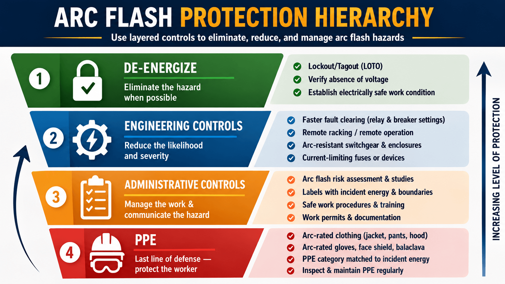
Notice that arc-rated PPE appears at the bottom of the hierarchy. PPE matters, but it should not be treated as a substitute for eliminating exposure, reducing clearing time, maintaining equipment, or using safer work methods.
What Is Arc Flash Protection?
Arc flash protection is a safety and engineering strategy used to reduce the chance that an electrical fault becomes a severe arc flash event and to limit the consequences if one occurs. It applies to switchgear, switchboards, motor control centers, panelboards, transformers, industrial power distribution systems, utility equipment, and other energized electrical assemblies where a fault can release thermal energy, pressure, light, sound, and molten metal.
The important distinction is that arc flash protection is not one product and not just a clothing requirement. A complete approach connects the power system study, short-circuit current, protective device clearing time, equipment condition, labels, work procedures, remote operation, and PPE selection. The goal is to reduce both the energy released and the chance that a person is in the exposure zone when a fault occurs.
A high available fault current is not the only concern. In some cases, a lower arcing current can make a protective device trip more slowly, which can increase incident energy. That is why arc flash protection must be reviewed with actual protective device curves and settings, not just with one fault-current number.
Arc Flash Protection vs Mitigation vs PPE
Search results often mix these terms together, but they are not identical. Arc flash protection is the full layered strategy. Arc flash mitigation usually refers to methods that reduce the incident energy or exposure. PPE is the worker’s final protective layer after the hazard has been evaluated and other controls have been considered.
| Term | Meaning | Typical examples |
|---|---|---|
| Arc flash protection | The complete strategy for reducing arc flash likelihood, severity, and worker exposure. | De-energizing, risk assessment, protective device settings, labels, safe work practices, engineering controls, PPE, and maintenance. |
| Arc flash mitigation | Engineering measures that reduce the energy released, reduce clearing time, contain effects, or move workers away from the hazard. | Zone selective interlocking, differential protection, maintenance mode, current-limiting devices, active mitigation, remote racking, and arc-resistant gear. |
| Arc-rated PPE | Personal protective equipment selected for the remaining hazard after the risk assessment and controls are considered. | Arc-rated clothing, hood, face shield, gloves, balaclava, hearing protection, and other equipment identified by the electrical safety program. |
PPE should not be treated as permission to work energized. It is used when a task-specific risk assessment determines that energized work is justified and residual exposure remains after other protection layers are considered.
Arc Flash Risk Assessment Workflow
Arc flash protection starts with a risk assessment that connects the electrical model to real field tasks. The workflow is not just a calculation exercise. It should identify the equipment, operating mode, task, likely exposure, hazard level, available controls, label information, PPE selection method, and review requirements.
| Workflow step | What happens | Protection outcome |
|---|---|---|
| Gather system data | Collect one-line diagrams, utility data, transformer data, cable lengths, equipment ratings, protective devices, and settings. | Creates a defensible model of the actual electrical system. |
| Perform short-circuit and coordination review | Determine available fault current and evaluate how breakers, fuses, and relays operate for faults at different locations. | Identifies which device clears the fault and how long the arc may last. |
| Calculate incident energy and boundary | Use accepted study methods to estimate exposure at a defined working distance. | Produces values used for labels, boundaries, and PPE selection. |
| Apply protection controls | Consider de-energizing, faster clearing, ZSI, differential protection, maintenance mode, current limiting, remote operation, and equipment changes. | Reduces energy, likelihood, or worker exposure where practical. |
| Label, train, and review | Apply labels, communicate safe work practices, train qualified personnel, and update the study after system changes. | Keeps field decisions aligned with the current hazard. |
How Faster Clearing Reduces Incident Energy
Incident energy is influenced by the arc current, how long the arc lasts, the working distance, voltage level, enclosure configuration, and the protective device response. Engineers often cannot change every factor, but they can evaluate how quickly the system detects and clears the arcing fault.
Clearing Time Is One of the Most Important Controls
The longer an arcing fault remains energized, the longer energy is released into the worker’s space. Faster clearing can come from instantaneous trip settings, short-time settings, zone selective interlocking, differential protection, current-limiting devices, or active arc flash mitigation. The engineering challenge is reducing clearing time without creating unacceptable nuisance trips or losing required selective coordination.
Lower Fault Current Does Not Always Mean Lower Risk
A common misconception is that the highest available fault current always produces the worst arc flash result. In reality, a lower arcing current can sometimes fall into a slower trip region on a breaker or relay curve. That longer clearing time can increase incident energy even though the current is lower.
Protection Must Match the Actual System Configuration
Arc flash labels and PPE decisions depend on the system as studied. A normally open tie breaker, standby generator, utility service change, transformer replacement, cable change, or relay setting update can change the available fault current and protective device operating time. Protection that looked acceptable in one operating mode may not be acceptable in another.
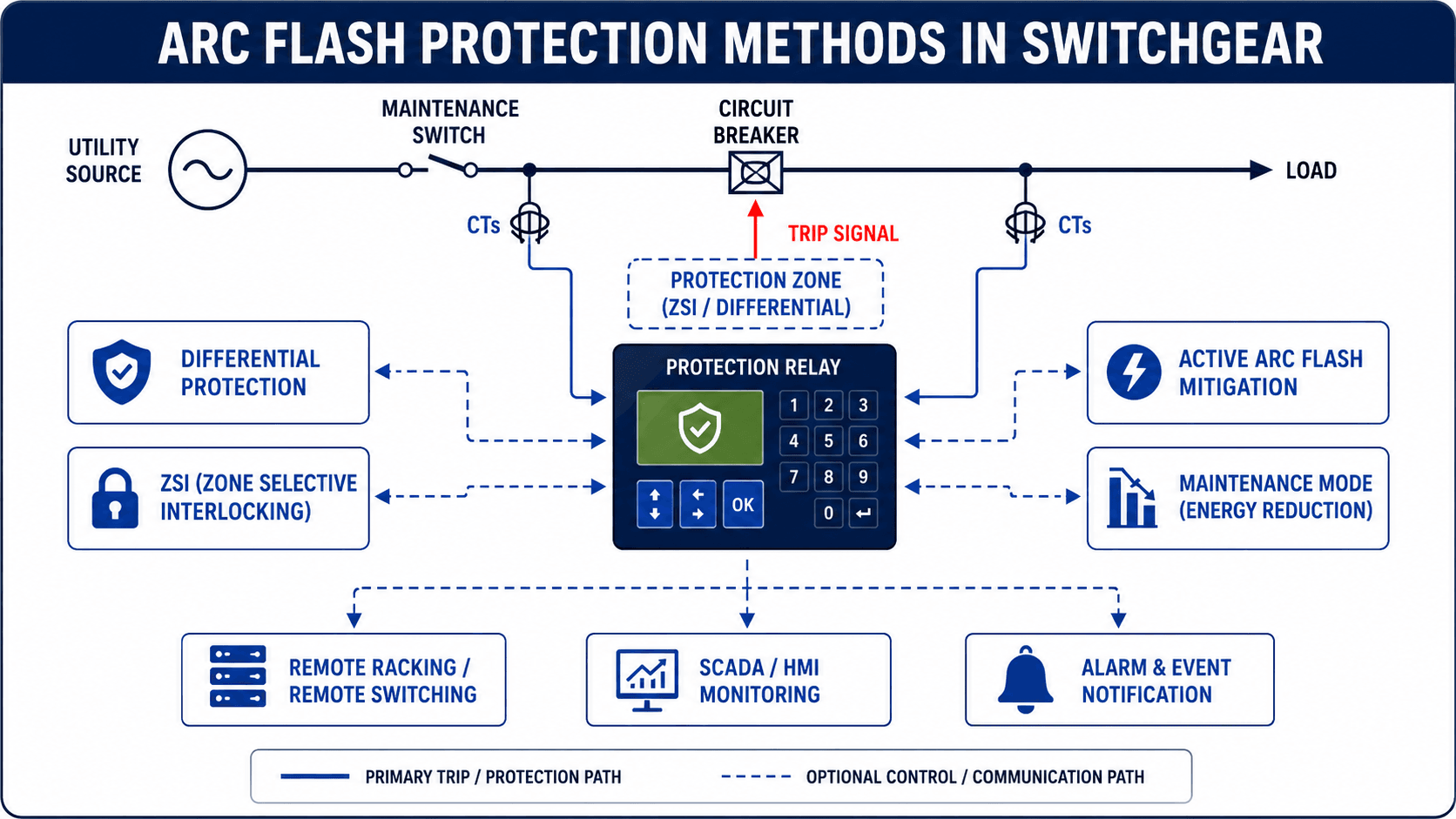
Arc Flash Protection Methods in Switchgear
Switchgear is one of the most common places where arc flash protection decisions become practical. The protection scheme must sense fault current, decide whether the fault is inside the protected zone, send a trip signal to the correct breaker, and keep people away from the hazard whenever possible.
| Protection method | What it does | Engineering tradeoff |
|---|---|---|
| Protective relay and breaker settings | Detects abnormal current and trips the breaker based on pickup thresholds, time delays, curves, and logic. | Faster settings can reduce incident energy, but settings must still coordinate with upstream and downstream devices. |
| Zone selective interlocking | Allows upstream and downstream breakers to communicate so the nearest device trips while upstream delay can be reduced. | Requires compatible devices, correct wiring or communication, and testing to confirm the interlocking logic works. |
| Differential protection | Compares current entering and leaving a protected zone to detect internal faults quickly. | Excellent for defined zones, but CT placement, ratios, saturation, wiring, and relay settings must be carefully reviewed. |
| Energy-reducing maintenance mode | Temporarily changes trip behavior during maintenance so faults clear faster while personnel are exposed. | It only helps when enabled at the right time and supported by clear procedures, indication, and operator discipline. |
| Current-limiting fuses or devices | Can reduce let-through energy by interrupting high fault currents quickly within their current-limiting range. | Performance depends on fault current level, fuse class, equipment coordination, and replacement practices. |
| Arc-resistant switchgear | Directs arc gases and pressure away from personnel when doors, covers, vents, and compartments are installed and secured as tested. | It helps manage consequences, but it does not replace hazard analysis, maintenance, correct installation, or safe work procedures. |
| Remote racking and remote switching | Moves the worker farther from the equipment during higher-risk operations. | It reduces exposure, but the system still needs proper protection, labeling, procedures, and equipment condition review. |
The same switchgear lineup can have very different arc flash risk depending on whether a maintenance switch is enabled, a tie breaker is closed, a generator is online, or relay settings were changed after the original study.
Arc Flash Protection Method Selection Table
No single method solves every arc flash problem. A useful protection review starts with the goal: reduce exposure, reduce clearing time, contain effects, improve field communication, or keep equipment operating as assumed. The method should match the task and the system.
| Protection goal | Methods to consider | Engineering notes |
|---|---|---|
| Eliminate worker exposure | De-energize, lockout/tagout, verify absence of voltage, remote operation. | Usually the strongest protection strategy when the work can be planned and equipment can be safely isolated. |
| Reduce clearing time | Relay settings, instantaneous trip, ZSI, differential protection, maintenance mode, active arc mitigation. | Review selective coordination, nuisance trip risk, operating modes, and whether the settings are controlled after implementation. |
| Reduce let-through energy | Current-limiting fuses, current-limiting breakers, other current-limiting devices. | Effectiveness depends on available fault current and whether the device operates in its current-limiting range. |
| Contain arc effects | Arc-resistant switchgear, pressure relief paths, correctly installed doors and covers. | Must be installed, maintained, and operated within the equipment’s tested configuration. |
| Reduce task exposure | Remote racking, remote switching, remote monitoring, closed-door operation where appropriate. | Does not necessarily reduce incident energy, but can reduce the chance that a person is inside the hazard zone. |
| Improve field communication | Updated labels, procedures, training, energized work review, task planning. | Labels and procedures must match the current study and actual equipment condition. |
How Arc Flash Labels Support Protection
Arc flash labels are field communication tools. They do not make equipment safe by themselves, but they help qualified personnel understand the studied hazard before performing a task. A label should be tied to the current arc flash risk assessment and the facility’s electrical safety program.
| Label information | Why it matters | Practical check |
|---|---|---|
| Nominal system voltage | Identifies the voltage class of the equipment being approached or worked on. | Confirm the equipment identification and voltage match the actual field condition. |
| Arc flash boundary | Communicates the distance where an arc flash hazard may exist for the studied condition. | Use it with task planning, barricades, access control, and qualified-person requirements. |
| Incident energy or PPE category method | Supports PPE selection according to the facility’s approved method. | Do not mix calculation-based labels and table/category methods without a clear program basis. |
| Working distance | Connects the calculation to the assumed worker position. | Recognize that a different task position can change actual exposure. |
| Equipment identification | Prevents labels from being applied to the wrong switchboard, panel, or compartment. | Compare the label to the one-line diagram and field equipment nameplate. |
| Study date or reference | Helps determine whether the label reflects the latest system configuration. | Review after changes to utility service, transformers, protective settings, feeders, generators, or operating modes. |
Arc flash protection decisions should be based on a project-specific study and the facility’s electrical safety program, not on generic assumptions from voltage class alone.
What an Arc Flash Study Provides for Protection
Arc flash protection depends on a study because the hazard cannot be judged from voltage alone. A low-voltage switchboard can still have a significant arc flash hazard if the available fault current and clearing time produce high incident energy. The study turns power system data into practical field outputs such as labels, approach boundaries, incident energy levels, and PPE selection information.
| Study item | Why it matters | Protection decision it supports |
|---|---|---|
| One-line diagram | Shows the actual electrical path, equipment hierarchy, and protective device locations. | Identifies which breaker, fuse, relay, or zone should clear each fault location. |
| Utility fault current | Defines the source strength available at the service point. | Supports short-circuit duty checks and arc flash calculation inputs. |
| Transformer impedance | Controls how much fault current passes downstream into the distribution system. | Changes expected arc current and protective device operating time. |
| Cable and bus data | Conductor impedance affects fault current at each equipment location. | Helps determine whether downstream equipment has a different hazard than upstream equipment. |
| Protective device settings | Trip curves and delays determine how long the arc remains energized. | Supports mitigation studies, coordination reviews, and maintenance mode decisions. |
| Working distance | Represents the expected distance between the worker and the arc source. | Directly affects calculated exposure and label information. |
| Operating modes | Different source, tie, and generator configurations can change fault current and clearing paths. | Prevents labels from being based on only one convenient system arrangement. |
Senior Engineer Arc Flash Protection Review Checklist
A useful arc flash protection review asks whether the study, equipment, settings, labels, and work practices still represent the actual system. The checklist below is designed as a practical review tool for engineering, maintenance, and operations discussions.
Start with the current one-line diagram, confirm fault-current and equipment data, review protective device settings and operating modes, compare the study outputs to field labels, then select engineering controls and PPE for the remaining exposure.
| Review check | What to look for | Why it matters |
|---|---|---|
| One-line diagram is current | New feeders, transformers, generators, tie breakers, or switchgear changes are shown. | Arc flash calculations are only meaningful when the model matches the field system. |
| Utility and transformer data are verified | Fault-current values, transformer size, impedance, grounding, and source assumptions are documented. | Incorrect source data can change calculated arcing current and device clearing time. |
| Relay and breaker settings are controlled | Settings in the field match the study and are managed through a change-control process. | A small setting change can move a fault into a slower trip region and raise incident energy. |
| Maintenance mode is clearly managed | Switch position, indication, procedures, and return-to-normal steps are documented. | Energy-reduction mode only reduces risk when personnel actually enable and verify it correctly. |
| Labels match the latest study | Equipment labels show current incident energy, boundary, voltage, and required information from the latest review. | Outdated labels can lead workers to select the wrong PPE or misunderstand the hazard. |
| Equipment condition is acceptable | Doors, covers, interlocks, breakers, relays, CT wiring, and ventilation paths are maintained. | Protection depends on equipment operating as assumed during the study. |
| Remote work methods are considered | Remote racking, remote switching, or remote monitoring can reduce worker exposure. | Moving the worker away from the equipment can reduce exposure even if the calculated energy remains high. |
Engineering Use in Power Systems
Arc flash protection is used during design, studies, commissioning, maintenance planning, and operations. In a design review, engineers may compare equipment options, interrupting ratings, relay schemes, and working clearances. In an existing facility, the focus often shifts to label accuracy, breaker maintenance, settings review, work permits, and ways to reduce exposure during troubleshooting.
- New equipment design: select switchgear, breakers, fuses, relays, CTs, and equipment configurations that support reliable fault clearing and safer maintenance.
- Existing system review: compare current field conditions against the arc flash study, labels, protective device settings, and operating procedures.
- Maintenance planning: decide whether equipment can be de-energized, remotely operated, placed in maintenance mode, or worked only under controlled energized-work conditions.
- Protection coordination: evaluate whether faster tripping can reduce arc energy without creating unacceptable coordination or reliability issues.
If a mitigation option reduces incident energy but causes upstream equipment to trip for downstream faults, the design may create a reliability problem. Good arc flash protection balances worker safety, coordination, equipment duty, and operational consequences.
Standards, Codes, and Safety Context
Arc flash protection sits at the intersection of electrical engineering and workplace electrical safety. OSHA establishes employer safety obligations, NFPA 70E is widely used for electrical safe work practices and risk assessment, IEEE 1584 is widely used for arc flash calculation methodology, and the NEC includes arc energy reduction provisions for certain equipment and overcurrent protective device applications.
NEC requirements may apply to certain overcurrent protective devices and equipment configurations, including arc energy reduction provisions for some large circuit breakers. The exact requirements depend on the adopted code edition, equipment type, project jurisdiction, and authority having jurisdiction.
| Reference family | How it relates to arc flash protection | Practical use |
|---|---|---|
| OSHA | Workplace safety obligations and hazard-control expectations. | Frames the employer responsibility to identify hazards and provide safeguards. |
| NFPA 70E | Electrical safe work practices, risk assessment, energized work, labels, boundaries, and PPE selection methods. | Used by facilities and safety programs to manage electrical work around energized equipment. |
| IEEE 1584 | Arc flash calculation methodology used in many engineering studies. | Supports calculation of incident energy and arc flash boundary when study inputs are available. |
| NEC arc energy reduction provisions | Energy-reduction requirements for certain equipment and overcurrent protective devices. | Influences design choices such as maintenance switches, ZSI, differential protection, and active mitigation. |
Engineering Judgment and Field Reality
Arc flash protection is only as good as the assumptions behind it. A label may look precise, but it usually depends on a modeled system state, specific utility data, a particular working distance, known protective device settings, and equipment that is maintained well enough to operate as expected.
In the field, engineers and maintenance teams must watch for missing covers, unlatched doors, untested breakers, temporary feeders, undocumented setting changes, generator operating modes, and equipment that has been modified since the last study. These details can matter more than a polished report.
Qualified Personnel Matter
Arc flash protection depends on qualified personnel who understand the equipment, nominal voltage, approach boundaries, PPE selection, shock hazards, arc flash labels, and the difference between normal operation and energized electrical work. The same equipment can have very different risk depending on the task being performed.
Normal Operation Is Not the Same as Energized Work
Operating properly installed and maintained equipment with doors closed and covers secured is not the same risk profile as troubleshooting, voltage testing, racking equipment, removing covers, or interacting with exposed energized conductors. Arc flash protection decisions should match the actual task, not just the equipment nameplate.
An arc flash label should not be treated as permanent. If the electrical system, operating mode, utility source, transformer, protective device settings, or equipment condition changes, the label may no longer represent the actual hazard.
When This Breaks Down
Simplified arc flash protection explanations break down when they ignore system configuration, operating modes, equipment condition, or coordination requirements. A protection method that works well in one lineup may not transfer directly to another without a study and field verification.
- Outdated studies: incident energy values can become unreliable after system changes, utility source changes, or protective device setting updates.
- Unverified maintenance mode: a maintenance switch does not help if workers do not enable it, confirm it, and restore it correctly after work.
- Poor equipment condition: dirty, damaged, misadjusted, or untested equipment may not clear faults as assumed.
- Single-mode assumptions: a system with ties, generators, or alternate feeds can have different arc flash hazards under different configurations.
- Coordination conflicts: reducing a delay can lower incident energy but may also trip larger portions of the facility if selectivity is not reviewed.
Common Arc Flash Protection Mistakes
Many arc flash protection problems come from treating the topic as a paperwork exercise rather than a live power systems engineering issue. The practical goal is not simply to produce labels; it is to keep the electrical system, protection settings, work methods, and PPE decisions aligned with the actual hazard.
| Common mistake | Why it creates risk | Better practice |
|---|---|---|
| Equating arc flash protection with PPE only | PPE does not prevent the event and may not address blast pressure, equipment damage, or exposure reduction. | Use the hierarchy: de-energize, apply engineering controls, manage work, then select PPE for residual risk. |
| Ignoring protective device clearing time | Slow trip regions can drive high incident energy even when fault current is not at its maximum. | Review relay settings, breaker curves, ZSI, differential schemes, and maintenance mode options. |
| Using labels after system modifications | Changed equipment or settings can invalidate incident energy and boundary values. | Update the model and labels after meaningful electrical system changes. |
| Forgetting alternate operating modes | Generator operation, closed ties, or utility changes may alter current paths and clearing times. | Evaluate credible operating modes during the arc flash study. |
| Skipping breaker and relay maintenance | Protection assumptions depend on the device operating when and how the study assumes. | Test, inspect, maintain, and document critical protection equipment. |
Do not treat PPE as permission to work energized, use outdated labels, assume all equipment at the same voltage has the same hazard, change relay settings without updating the study, ignore alternate feeds, or assume arc-resistant gear eliminates all arc flash risk.
Relevant Manuals, Standards, and Design References
Arc flash protection should be explained in plain language, but the underlying safety program and calculation approach should still be tied to recognized references. For a public safety-oriented source, OSHA provides useful context for electric-arc flash hazards, employer responsibilities, hazard assessment, and recognized calculation methods.
- OSHA arc flash guidance: OSHA guidance on protecting employees from electric-arc flash hazards explains arc flash hazards, workplace safeguards, and the importance of identifying and assessing the hazard before selecting protective measures.
- Engineering study context: Arc flash protection decisions are typically supported by short-circuit analysis, protective device coordination, equipment data, working distance assumptions, and a documented arc flash risk assessment.
- Project-specific criteria: Final application depends on the facility, equipment, owner requirements, applicable adopted codes, safety program requirements, and authority having jurisdiction.
Frequently Asked Questions
Arc flash protection is a layered approach used to reduce the likelihood, severity, and worker exposure associated with arc flash events. It includes de-energizing equipment, engineering controls, protective device coordination, arc flash studies, labels, safe work procedures, PPE, and maintenance.
No. Arc-rated PPE is only the last line of defense. Arc flash protection also includes eliminating energized work where possible, reducing clearing time, using remote operation, improving protective device settings, applying equipment controls, maintaining equipment, and communicating hazards through labels and procedures.
Faster clearing can reduce the duration of the arcing event, which can reduce incident energy exposure when the protection scheme operates correctly. Engineers evaluate relay settings, breaker clearing time, zone selective interlocking, differential protection, current-limiting devices, and maintenance modes to reduce clearing time while still maintaining reliable coordination.
Common arc flash protection methods include protective relays, circuit breakers, current transformers, zone selective interlocking, differential protection, energy-reducing maintenance switches, current-limiting fuses, active arc flash mitigation, arc-resistant switchgear, remote racking, remote switching, and monitoring systems.
An arc flash study should be reviewed when system configuration, utility fault current, transformers, feeders, switchgear, protective device settings, generators, operating modes, or equipment condition changes. Labels and PPE decisions are only useful when the study reflects the actual electrical system.
Summary and Next Steps
Arc flash protection is a layered power systems strategy that combines hazard elimination, faster fault clearing, protective devices, safe work procedures, labels, PPE, and maintenance. It is most effective when the electrical system study, field equipment, operating modes, and worker procedures all match.
The most important practical lesson is that PPE is not the starting point. Engineers and facility teams should first ask whether work can be de-energized, whether clearing time can be reduced, whether equipment can be remotely operated, and whether the labels and study still reflect the actual system.
Where to go next
Continue your learning path with related Turn2Engineering power systems resources.
-
Short Circuit Analysis
Review how available fault current is calculated and why it affects equipment duty, protective settings, and safety studies.
-
Protective Relays
Learn how relays detect abnormal conditions, issue trip signals, and support faster fault clearing.
-
Overcurrent Protection
Understand how breakers, fuses, and trip curves protect conductors and equipment during overloads and faults.