Key Takeaways
- Core idea: Timber structures use wood or engineered wood products as primary load-bearing elements, including beams, columns, trusses, frames, CLT panels, and glulam members.
- Engineering use: Engineers use timber systems for residential, commercial, institutional, industrial, roof, floor, wall, and mass timber building applications.
- What controls it: Load path, connection detailing, moisture control, serviceability, fire resistance, grain direction, and lateral stability often govern timber performance.
- Practical check: A timber member can look oversized and still be vulnerable if bearing, splitting, uplift, fastener spacing, drainage, or long-term deflection is ignored.
Table of Contents
Introduction
Timber structures are buildings or structural systems where wood or engineered wood products carry the main gravity and lateral loads. They include timber frames, heavy timber buildings, glulam beams and columns, CLT floors and walls, timber trusses, and hybrid systems. Their performance depends on load path, connection detailing, moisture control, fire design, and long-term serviceability.
Visual Guide to Timber Structures
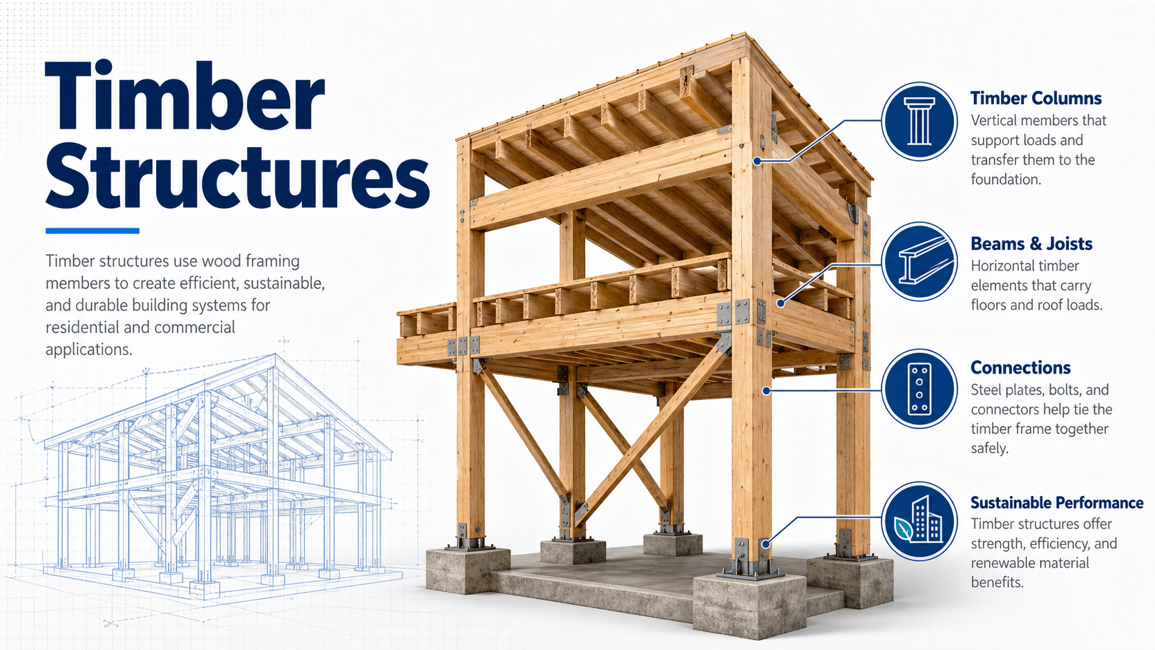
Notice that the members are only part of the story. The most important engineering questions are how loads transfer between elements, how the connections behave, and whether the timber is protected from moisture, fire exposure, excessive deflection, and instability.
What Are Timber Structures?
Timber structures are structural systems that use wood products as load-carrying components rather than simply as finishes or architectural trim. A timber structure may be a traditional post-and-beam frame, a heavy timber roof, a wood truss system, a glulam long-span hall, a CLT wall and floor building, or a hybrid system combining timber with steel and concrete.
In structural engineering, timber is treated as an anisotropic material, meaning its properties vary with grain direction. Strength, stiffness, shrinkage, bearing, splitting resistance, and connection behavior are different parallel and perpendicular to grain. That is one reason timber design is not just a matter of selecting a large beam; the details around loading direction, fasteners, moisture, and support conditions matter heavily.
| Timber system | Typical structural elements | Common applications |
|---|---|---|
| Timber frame | Posts, beams, braces, trusses, pegs, steel plates, or concealed connectors | Homes, halls, pavilions, churches, lodges, and exposed architectural structures |
| Heavy timber | Large sawn or engineered members with substantial cross sections | Warehouses, industrial buildings, historic structures, commercial interiors, and roof systems |
| Mass timber | CLT panels, glulam beams and columns, NLT, DLT, and structural composite lumber | Multi-family, office, school, institutional, and mid-rise buildings |
| Hybrid timber | Timber framing combined with steel connectors, concrete cores, topping slabs, or steel bracing | Projects where timber is used for gravity framing, speed, carbon reduction, or exposed finish |
How Timber Structures Carry Loads
Timber structures work by creating a continuous load path from roof and floor surfaces into supporting members, vertical elements, foundations, and soil. The load path must remain continuous for gravity loads such as dead, live, roof, and snow loads, and for lateral loads such as wind and seismic forces.
Gravity load path
Gravity loads usually begin at roof decking, floor sheathing, CLT panels, joists, or purlins. These elements transfer load to beams, girders, trusses, walls, or columns. The reactions then move through bearing plates, seats, column bases, sill plates, anchors, and foundations. If one support or connection is weak, the whole load path may be compromised.
Lateral load path
Lateral loads require diaphragms, chords, collectors, shear walls, braced frames, hold-downs, anchors, and foundations to act together. In timber buildings, lateral design is often governed by connection stiffness, diaphragm nailing or screw patterns, wall anchorage, uplift, overturning, and drift rather than by the strength of a single beam.
Connection behavior
Timber connections transfer forces through bearing, fastener shear, fastener withdrawal, tension straps, steel plates, dowels, bolts, screws, hangers, or bearing seats. Connections can introduce local crushing, splitting, moisture traps, eccentricity, and reduced fire cover. For many timber structures, the connection is the governing design problem.
Where Timber Structures Are Used in Engineering
Timber structures are used when strength-to-weight efficiency, architectural warmth, prefabrication, renewable material selection, construction speed, or lower embodied carbon potential are important project goals. They are common in residential framing, exposed roof systems, long-span glulam halls, schools, offices, multi-family buildings, bridges, canopies, pavilions, and adaptive reuse projects.
- Roof systems: rafters, purlins, glulam arches, king post trusses, queen post trusses, scissor trusses, and heavy timber roof beams.
- Floor systems: joists, timber decking, CLT panels, glulam girders, and composite timber-concrete floor assemblies.
- Wall and lateral systems: wood shear walls, CLT wall panels, diaphragms, braced timber frames, collectors, and hold-downs.
- Architectural structures: exposed timber frames where the structural system is also part of the visual design.
- Mass timber buildings: prefabricated panelized systems using CLT, glulam, NLT, DLT, and related engineered wood products.
Before selecting timber for a project, check whether the controlling issue is strength, stiffness, vibration, fire rating, exposure, connection complexity, procurement lead time, or construction tolerance. Timber is often selected for its appearance and sustainability value, but the design usually succeeds or fails at the details.
Main Types of Timber Structures
The phrase timber structures covers several different structural families. A residential timber frame, a historic heavy timber warehouse, and a modern CLT office building all use wood structurally, but they do not behave or get detailed the same way.
Timber frame structures
Timber frame structures use posts, beams, braces, and trusses to form a visible load-bearing skeleton. Traditional timber frames may use mortise-and-tenon joinery, while modern frames often use steel plates, screws, bolts, concealed knife plates, or proprietary connectors. The frame must resist gravity loads, lateral sway, uplift, and connection eccentricity.
Heavy timber structures
Heavy timber structures use large wood members with enough cross section to provide robustness and, when designed correctly, predictable charring behavior in fire. These systems are common in older warehouses and modern exposed commercial spaces. Their design depends on member size, bearing, connections, lateral stability, and fire-resistance requirements.
Mass timber structures
Mass timber structures use engineered wood products such as cross-laminated timber, glue-laminated timber, nail-laminated timber, dowel-laminated timber, and structural composite lumber. These systems are often prefabricated and can be used for floors, roofs, walls, beams, columns, shafts, and hybrid assemblies.
Hybrid timber structures
Hybrid timber structures combine timber with steel, concrete, masonry, or other systems. A common example is glulam or CLT gravity framing around a concrete core, or timber floors supported by steel beams. Hybrid design can solve lateral, vibration, fire, span, or constructability challenges that pure timber framing may not handle efficiently.
Key Factors That Control Timber Structural Performance
Timber performance depends on more than member size. Wood is moisture-sensitive, direction-dependent, connection-sensitive, and affected by long-term loading. The best timber design decisions consider both analysis results and field conditions.
| Factor | Why it matters | Engineering implication |
|---|---|---|
| Grain direction | Wood properties differ parallel and perpendicular to grain. | Check bearing, splitting, shrinkage, fastener layout, and tension perpendicular to grain. |
| Moisture content | Moisture affects shrinkage, swelling, decay risk, fastener corrosion, and dimensional stability. | Detail drainage, ventilation, flashing, end-grain protection, and separation from wet materials. |
| Connection detailing | Fasteners and steel plates concentrate force into local wood fibers. | Check spacing, edge distance, group action, withdrawal, bearing, splitting, and constructability. |
| Serviceability | Timber floors and beams may be governed by deflection, vibration, or creep. | Evaluate stiffness, span-depth ratios, floor frequency, long-term loading, and user comfort. |
| Fire exposure | Large timber can char, but exposed area, member size, protection, and connections matter. | Coordinate member sizing, encapsulation, connection protection, fire ratings, and building code limits. |
| Lateral stability | Wind and seismic forces require diaphragms, collectors, hold-downs, and shear-resisting elements. | Confirm a continuous lateral load path, adequate drift control, anchorage, and overturning resistance. |
Design Checks for Timber Members and Systems
Timber design is usually checked through a combination of member capacity, connection capacity, stability, serviceability, fire, and durability requirements. For an educational overview, a useful way to think about design is the demand-to-capacity relationship: the applied demand should not exceed the adjusted design resistance for the member, connection, or system being checked.
The applied demand may be bending moment, shear, axial compression, axial tension, bearing, uplift, fastener load, diaphragm force, or overturning force. The adjusted design capacity depends on the material, grade, member size, load duration, moisture condition, temperature, stability, connection details, and the governing design method.
- Bending Controls beams, rafters, joists, purlins, glulam girders, and some CLT floor strips.
- Shear Important near supports, concentrated loads, notches, holes, and short-span members.
- Axial Controls posts, columns, truss members, braces, chord forces, and hold-down elements.
- Bearing Critical at beam seats, column bases, supports, plates, and concentrated load transfer points.
- Serviceability Includes deflection, vibration, creep, shrinkage movement, and visual performance of exposed members.
Timber Structure Design Review Checklist
A timber structure should be reviewed as a full system, not as a set of isolated beams. The checklist below helps organize the major decisions that experienced engineers review before a timber design is considered coordinated.
Define the system → establish gravity and lateral load paths → select timber products → check member strength and serviceability → design connections → review fire and moisture detailing → coordinate fabrication tolerances → confirm construction sequencing and inspection requirements.
| Check or decision | What to look for | Why it matters |
|---|---|---|
| Continuous load path | Clear transfer from roof/floor surfaces into beams, walls, columns, foundations, and lateral systems. | Discontinuous load paths create hidden weak points, especially at collectors, hold-downs, supports, and transfer levels. |
| Connection geometry | Fastener spacing, edge distance, steel plate fit-up, bolt holes, concealed plate clearances, and eccentricity. | Connections can govern capacity, stiffness, ductility, appearance, fire resistance, and constructability. |
| Moisture detailing | Drainage, flashing, ventilation, end-grain protection, roof overhangs, wall interfaces, and separation from concrete. | Moisture problems can reduce durability, trigger decay, distort members, and damage connections. |
| Serviceability | Deflection, vibration, floor bounce, creep, shrinkage gaps, and visual sag in exposed members. | A member may be strong enough but still unacceptable for occupant comfort, finishes, partitions, or long-term appearance. |
| Fire strategy | Required rating, exposed versus protected timber, char allowance, encapsulation, penetrations, and protected connections. | Fire design must coordinate architecture, code classification, member sizing, and connection protection. |
| Construction tolerance | Panel fit, camber, moisture movement, bearing seat alignment, lifting points, and installation sequence. | Prefabricated timber can be fast and precise, but tolerance conflicts can be expensive once panels and connectors arrive on site. |
Example: Reviewing a Timber Roof Structure
Consider a timber roof over a community hall. The roof uses exposed timber trusses spanning between exterior walls, purlins spanning between trusses, and roof decking above the purlins. The structure looks simple, but several engineering checks are needed before the design is reliable.
Step 1: Trace the loads
Roof dead load, roof live load, wind uplift, and snow load are first applied to the roof deck. The deck transfers load to purlins, the purlins transfer reactions to truss top chords, the trusses transfer reactions to bearing walls or columns, and the walls or columns transfer load into the foundation.
Step 2: Check the controlling members
Purlins are checked for bending, shear, deflection, and bearing. Truss members are checked for axial tension or compression. Compression members require stability checks, while tension members require connection checks at panel points. The truss may be strong enough globally but still fail locally at a bolt group, notch, seat, or bearing point.
Step 3: Review uplift and lateral behavior
Wind uplift may control roof-to-truss and truss-to-wall anchorage. Lateral forces need a diaphragm, collectors, shear walls or bracing, and hold-downs. Exposed timber roof systems are often visually clean, but the hidden lateral load path must still be complete and inspectable.
Engineering Judgment and Field Reality
Timber structures are sensitive to the gap between design assumptions and field conditions. A calculation may assume dry service, clean bearing, centered loads, precise fastener installation, and protected end grain. Real projects introduce wet construction, delayed enclosure, tolerance stacking, misaligned seats, field-drilled holes, concealed water traps, and architectural changes that alter the load path.
Moisture is not just a maintenance issue in timber structures. It affects shrinkage, swelling, fastener performance, decay risk, finish quality, dimensional tolerance, and long-term serviceability. The best timber details shed water, allow drying, avoid trapping moisture behind steel plates, and keep vulnerable end grain protected.
Experienced engineers also watch for bearing perpendicular to grain, tension perpendicular to grain, unbraced compression edges, oversized holes, notches near supports, and load reversals from wind uplift. These details can control performance even when the main beam or column appears visually robust.
When This Breaks Down
Simplified descriptions of timber structures break down when they treat timber as a uniform material, ignore moisture, or assume that bigger members automatically solve the design problem. Timber performance depends on local details, long-term exposure, and the way members are connected into a complete structural system.
- Connection-dominated behavior: fasteners, steel plates, bolt groups, and bearing seats may control before member bending or axial strength is reached.
- Moisture exposure: exterior timber, poorly flashed details, wet construction, condensation, and trapped water can change durability and dimensional behavior.
- Serviceability limits: long spans may be governed by deflection, vibration, creep, or appearance rather than strength.
- Fire assumptions: charring behavior helps only when the member, exposure, connection protection, and code strategy are designed together.
- Lateral discontinuities: roofs, floors, shear walls, collectors, hold-downs, and foundations must connect into a complete wind and seismic load path.
Common Mistakes and Practical Checks
Many timber structure problems come from treating wood like a generic beam material instead of a directional, moisture-sensitive, connection-sensitive structural material. The checks below help catch common problems before they become field issues.
- Ignoring grain direction: bearing, splitting, shrinkage, and tension perpendicular to grain can control local performance.
- Underestimating connections: bolts, screws, plates, straps, and hangers need adequate spacing, edge distance, installation tolerance, and force transfer.
- Skipping long-term deflection: creep and sustained load can make a beam or floor perform differently over time than it did on day one.
- Forgetting uplift: roof systems may need continuous tension ties from roof framing into walls, foundations, and anchors.
- Trapping moisture: concealed steel plates, poorly sealed penetrations, exposed end grain, and wet bearing points can shorten service life.
Do not evaluate a timber structure by member size alone. Always trace the force into the next member, through the connection, into the support, and down to the foundation.
Relevant Timber Design Standards and References
Timber design depends on the project location, adopted code, building type, product type, and exposure condition. The references below are commonly used to understand wood behavior, design values, code context, and mass timber systems.
- AWC National Design Specification for Wood Construction: A primary U.S. design reference for wood members, connections, adjustment factors, and structural wood design procedures.
- International Building Code: Provides building code context for construction type, fire resistance, height and area limits, structural requirements, and mass timber classifications such as Type IV-A, IV-B, and IV-C where adopted.
- USDA Wood Handbook: A widely used engineering reference for wood material properties, moisture behavior, durability, strength, fire behavior, and wood as an engineering material.
- WoodWorks mass timber resources: Practical design guidance for CLT, glulam, NLT, DLT, gravity framing systems, delegated design, and mass timber detailing considerations.
Frequently Asked Questions
Timber structures are structural systems that use wood or engineered wood products as primary load-bearing elements. They may include timber beams, columns, trusses, frames, glulam members, CLT panels, shear walls, diaphragms, and hybrid timber-steel or timber-concrete assemblies.
Timber frame structures usually rely on large posts, beams, braces, and trusses to create an exposed skeletal frame, while mass timber structures use engineered panel and member products such as CLT, glulam, NLT, and DLT to form floors, roofs, walls, beams, and columns.
Timber structures can be designed for fire resistance, but the answer depends on member size, exposure, protection, connection detailing, occupancy, building height, sprinklers, and the governing building code. Large timber and mass timber members may develop a char layer, but fire performance must still be checked by design.
Timber design is often controlled by connection behavior, deflection, vibration, moisture exposure, fire requirements, bearing perpendicular to grain, lateral stability, and long-term creep rather than member strength alone. A strong timber member can still perform poorly if load path, detailing, and serviceability are not handled correctly.
Summary and Next Steps
Timber structures use wood and engineered wood products as structural systems, not just as finishes. They can include timber frames, heavy timber buildings, glulam beams and columns, CLT panels, timber trusses, wood diaphragms, shear walls, and hybrid assemblies.
The most important engineering ideas are load path, grain direction, connection behavior, moisture protection, fire strategy, serviceability, and lateral stability. Good timber design combines member sizing with practical detailing so the structure can carry loads, stay dry, resist movement, and remain inspectable over its service life.
Where to go next
Continue your learning path with related Turn2Engineering resources.
-
Timber Materials
Learn how species, grading, moisture, engineered wood products, durability, and fire behavior affect timber performance.
-
Truss Systems
Study how triangulated members carry roof, bridge, and long-span loads through axial tension and compression.
-
Load Bearing Structures
Review how structural systems collect, transfer, and support gravity and lateral loads from the building to the foundation.