Key Takeaways
- Core idea: Masonry structures use brick, concrete masonry units, stone, mortar, grout, reinforcement, and connections to form walls or systems that may carry gravity and lateral loads.
- Engineering use: Structural masonry is commonly used for bearing walls, shear walls, stair and elevator cores, fire-rated walls, retaining walls, foundation walls, and durable building envelopes.
- What controls it: Wall thickness, unit strength, reinforcement, grout, slenderness, openings, anchorage, lateral loads, moisture detailing, movement joints, and construction quality control performance.
- Practical check: Never assume a brick or block wall is only architectural; verify wall role, load path, support conditions, ties, reinforcement, and drawings before altering it.
Table of Contents
Introduction
Masonry structures are buildings or structural systems made from individual units such as brick, concrete masonry units, stone, or clay masonry bonded together with mortar. In structural engineering, masonry may act as a load-bearing wall, shear wall, foundation wall, retaining element, infill wall, partition, or veneer depending on how it is reinforced, supported, anchored, and detailed.
How Masonry Structures Carry Loads
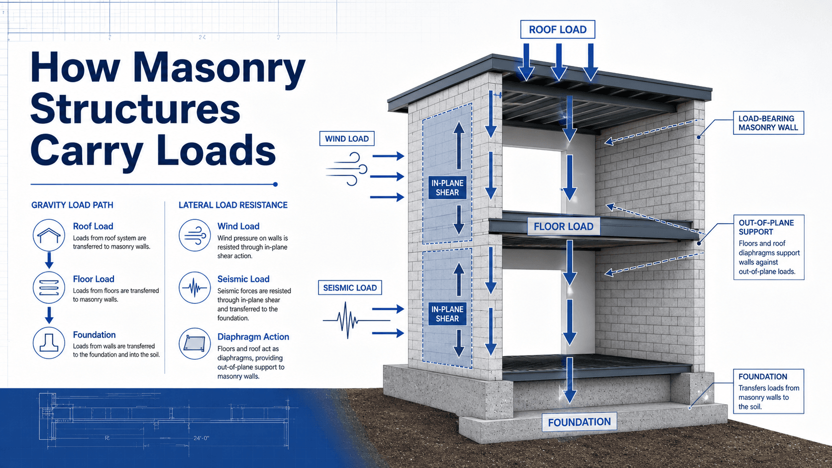
Notice that the wall, floor or roof diaphragm, connection, and foundation all work together. A strong masonry wall can still perform poorly if the diaphragm anchorage, lintels, reinforcement, movement joints, or foundation load path are incomplete.
What Is a Masonry Structure?
A masonry structure is built from discrete units arranged in courses and joined with mortar. The units may be brick, concrete block, stone, clay tile, or other masonry products. In modern structural work, masonry often also includes grout, reinforcing steel, bond beams, wall ties, anchors, flashing, weeps, control joints, and expansion joints.
The key structural idea is that masonry is usually strong in compression but limited in tension unless reinforced or otherwise detailed for the demand. That is why many modern masonry systems use steel reinforcement and grout to resist bending, shear, wind, seismic forces, concentrated bearing, and cracking around openings.
| Component | Primary role | Structural meaning |
|---|---|---|
| Masonry unit | Brick, CMU, stone, or clay unit forming the body of the wall | Provides compression capacity, mass, durability, fire resistance, and wall geometry. |
| Mortar joint | Bonds units and accommodates small dimensional variations | Transfers stress between units and affects bond strength, water resistance, and workmanship quality. |
| Grout | Fills selected cells or cavities around reinforcement | Helps reinforcement and masonry act together in reinforced wall systems. |
| Reinforcing steel | Adds tension, flexural, and shear resistance | Improves lateral load behavior, crack control, ductility, and wall strength after cracking. |
| Anchors and ties | Connect masonry to floors, roofs, frames, or backup walls | Control out-of-plane support, veneer stability, diaphragm transfer, and load path continuity. |
| Movement and moisture details | Control joints, expansion joints, flashing, weeps, sealants, and caps | Reduce uncontrolled cracking, leakage, corrosion, freeze-thaw damage, and long-term deterioration. |
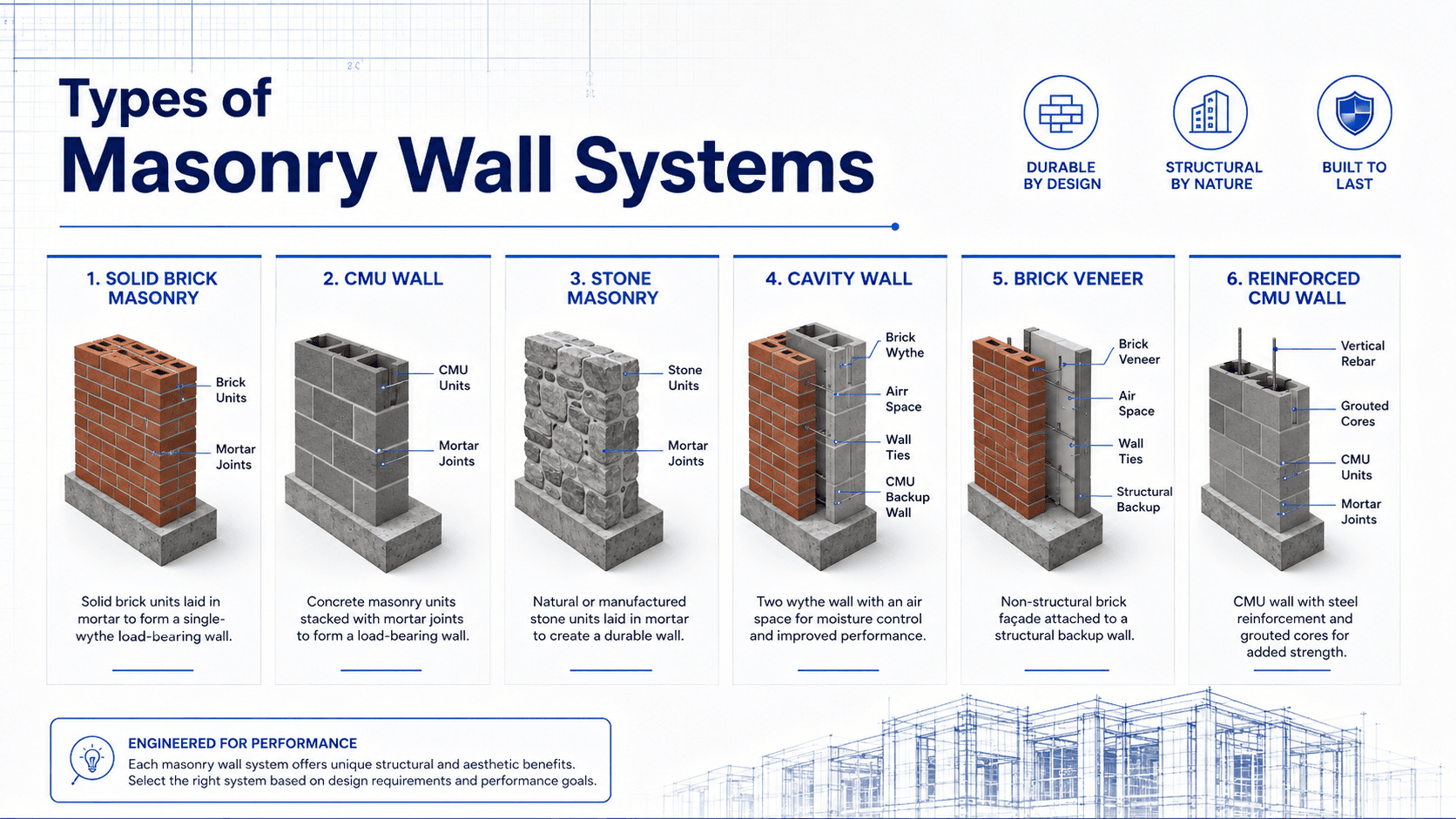
Types of Masonry Wall Systems
Searchers often use “masonry structures” when they need to understand the difference between brick masonry, CMU walls, stone masonry, cavity walls, veneer, and reinforced masonry. These systems can look similar from the outside but behave very differently under gravity, wind, seismic, moisture, and movement demands.
Load-Bearing Masonry
Load-bearing masonry walls support gravity loads from roofs, floors, beams, or walls above. They may also resist lateral loads if designed as shear walls or braced wall lines. Bearing masonry requires clear support conditions, adequate wall thickness, proper bearing area, and a continuous load path to the foundation.
Brick Masonry and Stone Masonry
Brick and stone masonry are common in historic structures, facades, chimneys, retaining walls, monuments, and architectural walls. Older brick or stone masonry may be multi-wythe and unreinforced, so assessment often depends on wall thickness, mortar condition, ties, water damage, anchorage, and how the wall connects to floors and roofs.
Masonry Veneer
Masonry veneer is usually not the primary structural system. It provides an exterior finish and weather surface while being tied back to a backup wall or frame. The veneer still needs engineering attention because wall ties, shelf angles, movement joints, flashing, weeps, and moisture control determine long-term performance.
Reinforced CMU Walls
Reinforced concrete masonry unit walls are common in schools, commercial buildings, stair and elevator cores, fire walls, warehouses, and utility structures. Vertical bars, bond beams, grouted cells, and foundation dowels allow the wall to resist forces that plain masonry cannot reliably carry alone.
Load-Bearing Masonry vs Veneer vs Infill
One of the most important masonry decisions is identifying the wall’s role. A masonry wall may carry the building, brace the building, enclose the building, divide interior spaces, or simply provide an exterior finish. The design checks change immediately once the role is known.
| Wall role | What it does | Key engineering checks |
|---|---|---|
| Load-bearing masonry wall | Supports vertical loads from floors, roofs, or walls above. | Axial load, eccentricity, bearing length, wall slenderness, openings, foundation load path, and local crushing. |
| Masonry shear wall | Resists wind or seismic loads in the plane of the wall. | Shear capacity, overturning, boundary elements, reinforcement, diaphragm transfer, anchorage, and foundation reactions. |
| Masonry veneer | Acts as an exterior cladding attached to a backup wall or frame. | Wall ties, shelf angles, out-of-plane stability, movement joints, flashing, weeps, and corrosion resistance. |
| Masonry infill wall | Fills a frame bay and may interact with the structural frame. | Frame interaction, drift compatibility, cracking, out-of-plane anchorage, and seismic behavior. |
| Non-load-bearing partition | Separates spaces without supporting primary gravity loads. | Out-of-plane support, movement tolerance, fire rating, deflection compatibility, and connection detailing. |
| Foundation or retaining masonry wall | Supports vertical loads, soil pressure, or grade changes. | Soil pressure, drainage, waterproofing, reinforcement, overturning, sliding, bearing, and frost exposure. |
If drawings are unavailable, do not classify a wall by appearance alone. Check wall thickness, location, continuity, bearing points, joist direction, roof/floor framing, openings, foundation alignment, and whether the wall continues through multiple levels.
How Masonry Structures Work Structurally
Masonry structures work by transferring loads through units, joints, reinforcement, diaphragms, connections, and foundations. A wall may be strong in isolation, but the complete structure only performs well when loads can move through a connected system without unsupported gaps or weak links.
Gravity Load Path
Gravity loads typically move from the roof or floor system into bearing walls, then down through the masonry into the footing and soil. Openings for doors, windows, louvers, or mechanical penetrations interrupt that path, so lintels, bond beams, pilasters, or reinforced jambs may be needed to redirect load.
Lateral Load Resistance
Wind and seismic forces create both in-plane and out-of-plane demands. In-plane loads can be resisted by masonry shear walls. Out-of-plane loads require adequate wall thickness, reinforcement, span limits, and connections to floor or roof diaphragms. Poor wall anchorage is one of the most important vulnerabilities in older masonry buildings.
Compression, Tension, and Cracking
Masonry units are usually much stronger in compression than in tension. That means cracking is not just a cosmetic issue; crack orientation can reveal restraint, settlement, shear, bending, corrosion, or moisture distress. Reinforcement does not eliminate cracking, but it can help control crack width and provide strength after cracking begins.
Openings, Lintels, and Load Redistribution
Openings are one of the highest-value areas to review because they reduce wall area and concentrate stresses. Lintels, bond beams, jamb reinforcement, end bearing, and movement joints around openings often control whether cracking remains serviceable or becomes a structural concern.
Reinforced Masonry Wall Components
Reinforced masonry turns a stack of units into a more capable structural wall by combining masonry compression capacity with steel reinforcement and grout. The details matter: reinforcement has to be placed correctly, cells must be grouted properly, and dowels must connect the wall to the foundation or supporting element.
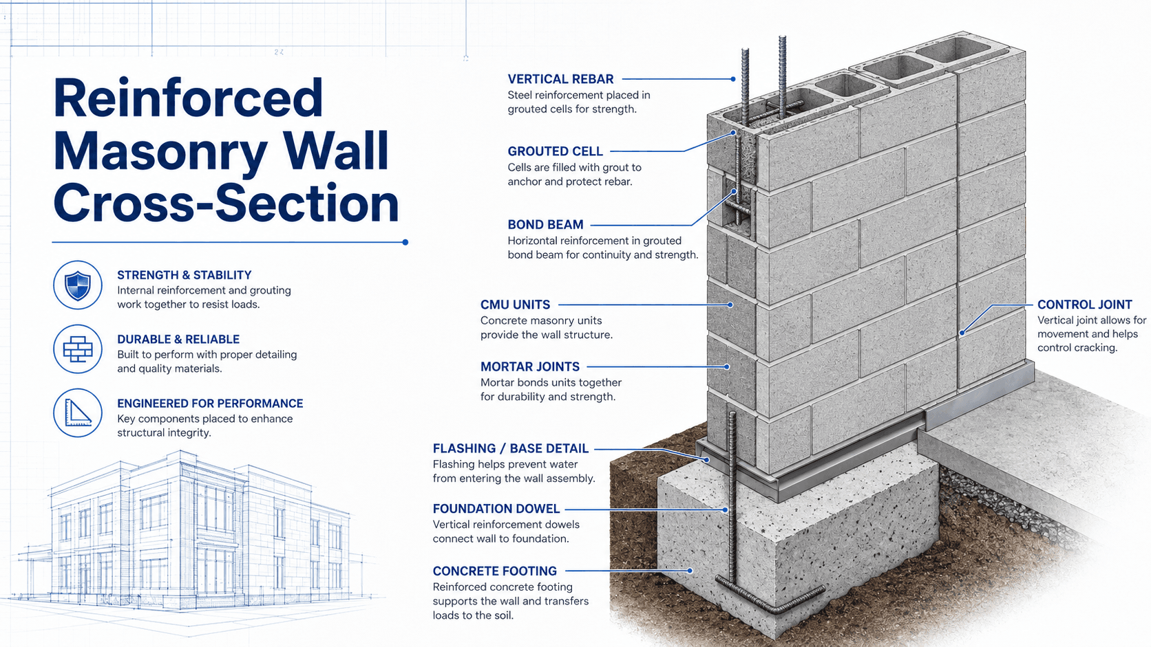
Vertical Reinforcement and Grouted Cells
Vertical bars are commonly placed in selected CMU cells and surrounded by grout. The grout transfers force between the steel and masonry so the wall can resist bending, shear, and axial load combinations more effectively than unreinforced masonry.
Bond Beams and Horizontal Reinforcement
Bond beams create horizontal continuity and help distribute concentrated loads, resist lateral forces, tie walls together, and frame openings. They are especially important near floor lines, roof lines, wall tops, lintels, diaphragm connections, and areas where continuity is needed.
Foundation Dowels and Anchorage
Foundation dowels connect reinforced masonry walls to footings, grade beams, slabs, or foundation walls. If dowels are missing, misplaced, too short, or not aligned with reinforced cells, the wall may not develop the intended base fixity, shear transfer, or overturning resistance.
Control Joints and Movement
Masonry moves with shrinkage, temperature, moisture, restraint, and foundation behavior. Control joints and expansion detailing help manage where movement occurs. Without planned joints, walls may create their own joints through uncontrolled cracking.
Where Masonry Structures Are Used
Masonry is used when a project needs durability, fire resistance, impact resistance, acoustic separation, thermal mass, architectural character, or robust wall systems. In structural engineering, the material is especially useful when walls can efficiently support or brace the building.
- Low-rise and mid-rise load-bearing wall buildings where gravity loads can transfer directly to foundations.
- Reinforced CMU shear walls in schools, warehouses, utility buildings, stair towers, elevator cores, and commercial structures.
- Fire-rated separation walls, shaft walls, exterior walls, retaining walls, foundation walls, and durable service spaces.
- Historic brick or stone buildings where assessment, repair, and retrofit require careful distinction between original behavior and modern code expectations.
- Architectural exterior envelopes where masonry veneer provides durability and appearance while a separate frame carries the main building loads.
Before calling a masonry wall “structural,” identify what it supports vertically, what restrains it laterally, how it connects to diaphragms, whether it is reinforced, and how loads reach the foundation.
What Controls Masonry Structural Performance?
Masonry performance is controlled by geometry, material strength, reinforcement, support conditions, openings, moisture detailing, and workmanship. A design that looks adequate on paper can still fail serviceability or durability expectations if grouting, joints, anchorage, flashing, or construction tolerances are poor.
| Factor | Why it matters | Engineering implication |
|---|---|---|
| Wall thickness and slenderness | Controls out-of-plane bending capacity, stability, and serviceability. | Tall or thin walls may require added reinforcement, intermediate support, pilasters, or reduced unbraced height. |
| Unit, mortar, and grout strength | Defines compression capacity, bond quality, and composite action with reinforcement. | Specified materials must match design assumptions and field quality must be verified during construction. |
| Reinforcement spacing and placement | Controls flexural strength, shear resistance, crack behavior, and ductility. | Bars must be located, lapped, grouted, and doweled correctly to perform as intended. |
| Openings and lintels | Doors, windows, and penetrations interrupt wall area and load paths. | Lintels, jamb reinforcement, bond beams, and bearing length must be checked around openings. |
| Diaphragm and wall anchorage | Controls out-of-plane wall support and lateral force transfer. | Weak anchorage can make an otherwise strong wall vulnerable during wind or seismic loading. |
| Moisture and movement detailing | Water intrusion and restraint can cause cracking, corrosion, efflorescence, and deterioration. | Flashing, weeps, sealants, control joints, expansion joints, and drainage planes must be detailed early. |
| Construction quality | Masonry performance depends heavily on workmanship, grouting, joint tooling, alignment, and inspection. | Field execution should be considered part of the structural system, not an afterthought. |
Masonry Structure Design Review Checklist
A useful masonry review starts with the load path, then moves into wall type, reinforcement, openings, movement, moisture, and constructability. The goal is not only to confirm strength, but also to prevent cracking, leakage, poor anchorage, and field details that do not match the design model.
Identify the wall role first: bearing wall, shear wall, veneer, infill, partition, retaining wall, or foundation wall. Then trace gravity and lateral loads, check support conditions, review openings and lintels, verify reinforcement and grout details, confirm movement joints, and compare drawings against likely field sequencing.
| Check or decision | What to look for | Why it matters |
|---|---|---|
| Wall role | Is it load-bearing, shear-resisting, veneer, partition, infill, foundation, or retaining masonry? | The same material can have completely different structural requirements depending on its role. |
| Load path continuity | Roof, floor, wall, lintel, diaphragm, and footing loads should have a clear route to support. | Discontinuous load paths cause distress even when individual components seem strong. |
| Openings and concentrated loads | Check lintels, bearing length, jamb reinforcement, bond beams, and eccentric bearing points. | Openings are common locations for cracking, crushing, and local overstress. |
| Out-of-plane support | Confirm roof/floor diaphragm support, anchors, span direction, and unbraced wall height. | Masonry walls can be vulnerable when lateral support is assumed but not detailed. |
| Reinforcement and grout | Review bar spacing, lap lengths, cell alignment, cleanouts, grout lifts, consolidation, and dowel location. | The wall only behaves as reinforced masonry if the reinforcement and grout can actually work together. |
| Movement and moisture | Review control joints, expansion joints, flashing, weeps, sealants, cap details, and drainage paths. | Many masonry problems are serviceability and durability failures rather than pure strength failures. |
| Constructability | Verify bar congestion, cleanouts, grout placement access, inspection points, and sequencing. | A design that cannot be built cleanly may not achieve the assumed structural behavior. |
Common Masonry Failure Modes
Masonry distress should be interpreted by pattern, location, history, and movement. A single crack does not automatically mean collapse risk, but the crack shape can point toward settlement, restraint, lateral load, lintel movement, corrosion, or moisture deterioration.
| Failure or distress mode | What it may look like | Common engineering concern |
|---|---|---|
| Stair-step cracking | Diagonal cracks following mortar joints near corners or openings | Foundation movement, lateral load effects, differential settlement, or restraint. |
| Vertical cracking | Cracks through units or joints, often between control joints or near restrained areas | Shrinkage, temperature movement, restraint, inadequate joint spacing, or foundation movement. |
| Out-of-plane movement | Wall bowing, separation from diaphragm, leaning, or displaced veneer | Insufficient anchorage, slender walls, seismic demand, wind pressure, or deteriorated ties. |
| Shear cracking | Diagonal cracks through a wall pier or shear wall panel | Lateral force demand exceeding wall shear capacity or insufficient reinforcement. |
| Crushing or bearing distress | Localized cracking, spalling, or damage below beams, lintels, or concentrated loads | Bearing stress, eccentric loading, inadequate bearing length, or weak units/mortar. |
| Lintel distress | Cracks above openings, sagging lintels, or diagonal cracks at window corners | Undersized lintel, corrosion, insufficient end bearing, or load redistribution around openings. |
| Moisture deterioration | Efflorescence, spalling, soft mortar, staining, or freeze-thaw damage | Poor flashing, trapped water, missing weeps, failed sealants, or exposure-driven deterioration. |
| Corrosion-related cracking | Cracking or spalling near embedded steel, shelf angles, lintels, ties, or reinforcement | Moisture exposure, inadequate protection, failed flashing, or insufficient corrosion resistance. |
Masonry vs Concrete, Steel, and Wood Systems
Masonry is not automatically better or worse than other structural systems. It is most competitive when walls are already useful for enclosure, fire separation, durability, sound separation, or lateral resistance. It becomes less efficient when long open spans, high ductility demand, rapid erection, or lightweight construction are the controlling goals.
| System | Strengths | Limitations | Best fit |
|---|---|---|---|
| Masonry | Durable, fire-resistant, strong in compression, good acoustic separation, useful wall mass | Heavy, labor-sensitive, limited tension without reinforcement, movement and moisture detailing matter | Wall-dominant buildings, cores, fire walls, schools, service buildings, durable enclosures |
| Reinforced concrete | Versatile, strong, monolithic, useful for frames, slabs, walls, and foundations | Formwork, curing, weight, congestion, and construction sequencing can control cost | Frames, foundations, slabs, walls, podiums, heavy structures, and complex shapes |
| Steel | High strength-to-weight ratio, fast erection, long-span capability | Fire protection, corrosion protection, vibration, and connection detailing may control | Long spans, open floor plans, industrial buildings, high-rise frames |
| Wood | Lightweight, fast, common for residential and low-rise construction | Moisture, fire rating, shrinkage, acoustics, and height limits can control | Residential, low-rise commercial, light-frame buildings, and mass timber applications |
Engineering Judgment and Field Reality
Real masonry structures rarely behave like perfect textbook walls. Openings get added, anchors are missed, cells are not always fully grouted, old walls may not match drawings, and moisture details can govern long-term performance more than the nominal compressive strength of the units.
Existing buildings require special caution. Historic brick or stone masonry may have multi-wythe walls, unknown ties, deteriorated mortar, hidden voids, unreinforced walls, and flexible diaphragms. A wall that has stood for decades may still be vulnerable if its support conditions change during renovation.
The most important masonry question is often not “Is the block strong enough?” It is “Does the wall have a complete load path, proper anchorage, controlled movement, moisture protection, and construction quality that matches the design assumptions?”
When This Breaks Down
The simplified idea that masonry is strong, durable, and load-bearing breaks down when tension, movement, lateral loading, moisture, or construction defects control behavior. Masonry is reliable when detailed as a system, but it can be unforgiving when connections and movement are ignored.
- Unreinforced masonry may perform poorly under out-of-plane seismic or wind demands when diaphragms and anchors are weak.
- Veneer can crack, bulge, or detach when ties, shelf angles, movement joints, or moisture details are missing or deteriorated.
- Openings can create weak piers and stress concentrations if lintels, jambs, bearing, and reinforcement are not coordinated.
- Foundation movement can create stair-step cracks or wall distortion even when the masonry units themselves are not defective.
- Moisture can corrode embedded steel, weaken mortar, create freeze-thaw damage, and turn small detailing issues into long-term structural repairs.
- Frame drift can damage infill or veneer when movement compatibility is not considered during lateral system design.
Common Mistakes and Practical Checks
Many masonry problems come from treating masonry as either purely architectural or purely structural. Good engineering practice keeps both in view: the wall has to carry load, accommodate movement, drain water, connect to the building, and remain buildable.
- Assuming brick veneer is a load-bearing wall because it looks massive from the outside.
- Removing or cutting masonry without first confirming bearing, lateral support, utilities, and load redistribution.
- Ignoring control joints, expansion joints, and shrinkage behavior until random cracks appear.
- Detailing reinforcement but not confirming grout placement, lap lengths, dowels, cleanouts, and inspection access.
- Checking wall strength but overlooking flashing, weeps, sealants, cap details, and corrosion protection.
- Forgetting that diaphragm anchorage may control wall stability during lateral loading.
- Treating existing masonry as modern reinforced masonry without confirming reinforcement, ties, wythes, mortar condition, and wall anchorage.
The most dangerous assumption is that a masonry wall is safe to modify because it appears to be “just block” or “just brick.” Wall role, reinforcement, anchorage, and support conditions must be verified before openings, removals, or renovations.
Codes, Standards, and Practical Design References
Masonry design depends on the adopted building code, project criteria, material specifications, inspection requirements, and local authority requirements. For a structural engineering resource page, the key point is to understand the behavior first, then use the governing code and specification documents for final design requirements.
- The Masonry Society: TMS 402/602 Building Code Requirements and Specification for Masonry Structures provides the primary masonry code and specification framework commonly referenced for structural masonry design and construction requirements.
- Project-specific criteria: Local amendments, owner requirements, seismic design category, wind exposure, fire ratings, durability exposure, and inspection requirements may control final detailing.
- Engineering use: Engineers use masonry references to check wall strength, reinforcement, anchorage, veneer support, movement joints, construction tolerances, and special inspection expectations.
Frequently Asked Questions
A masonry structure is a building or structural system made from units such as brick, concrete block, stone, or clay masonry bonded with mortar. In structural engineering, masonry may act as a load-bearing wall, shear wall, foundation wall, retaining wall, partition, infill, or veneer depending on how it is detailed and connected.
No. Some masonry walls support roof, floor, wind, or seismic loads, while others are partitions, infill panels, or exterior veneers attached to another structural frame. Wall thickness, reinforcement, location, supports, connections, and the original drawings must be reviewed before assuming a masonry wall is structural or non-structural.
Reinforced masonry uses steel reinforcement and grout to improve tension, flexure, shear, ductility, and lateral load resistance. Unreinforced masonry relies mostly on unit strength, mortar bond, wall thickness, mass, and compression, which can make it more vulnerable to cracking, out-of-plane movement, and seismic damage when anchorage is poor.
Masonry cracking can be caused by foundation movement, shrinkage, temperature movement, moisture expansion, restraint, corrosion of embedded steel, poor lintel support, overloading, or lateral forces. The crack pattern matters because stair-step, vertical, horizontal, and diagonal cracks can point to different structural or serviceability issues.
Summary and Next Steps
Masonry structures are more than brick, block, or stone walls. They are structural systems that rely on units, mortar, grout, reinforcement, anchors, diaphragms, movement joints, moisture details, and foundations working together.
The most important concepts are wall role, load path, reinforcement, lateral support, openings, movement, durability, and field verification. A well-designed masonry structure can be strong and durable, but weak anchorage, poor grouting, unplanned movement, or water intrusion can control performance.
Where to go next
Continue your learning path with related Turn2Engineering resources.
-
Load Bearing Structures
Learn how structural systems support gravity loads and transfer forces safely to the foundation.
-
Load Path Analysis
Review how forces move through walls, floors, diaphragms, connections, and foundations.
-
Steel Reinforcement
Understand how reinforcement improves tension resistance, crack control, and ductility in reinforced structural materials.