Key Takeaways
- Core idea: HVDC systems transmit bulk electric power using high-voltage direct current instead of alternating current.
- Engineering use: They are commonly evaluated for long-distance corridors, submarine cables, offshore wind, underground links, and asynchronous grid ties.
- What controls it: The decision depends on converter station cost, line or cable distance, power rating, controllability, AC grid strength, losses, and protection requirements.
- Practical check: HVDC is not automatically better than AC; it becomes attractive when system-level benefits justify the cost and complexity of power electronic converter stations.
Table of Contents
Introduction
HVDC systems are high-voltage direct current transmission systems used to move large amounts of electric power through DC overhead lines, underground cables, or submarine cables. A typical HVDC link converts AC power to DC at one converter station, transmits it over a DC path, then converts it back to AC for the receiving grid.
How an HVDC System Moves Power
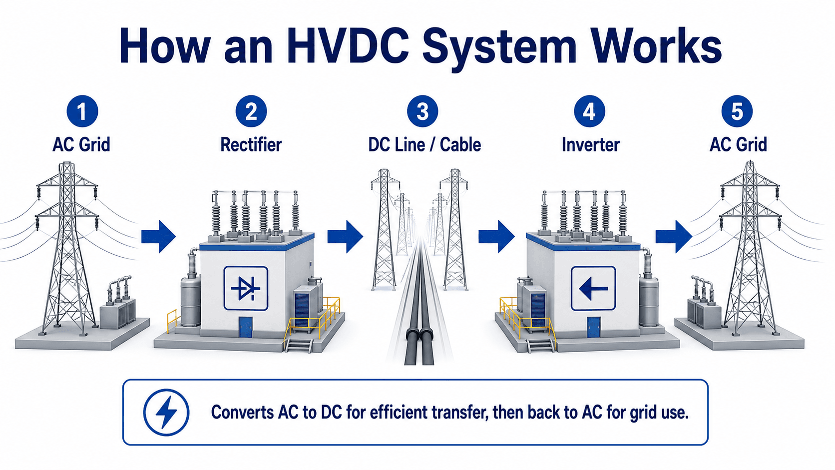
The important point is that the DC link is only one part of the system. The converter stations, controls, filters, protection, and AC-grid interfaces are what make an HVDC project behave like a controllable power system asset rather than a simple transmission line.
What is an HVDC system?
An HVDC system is a complete power transmission arrangement that uses direct current at high voltage to transfer real power between two points. It normally includes AC switchyards, converter transformers, valve halls or converter modules, filters, smoothing equipment, DC overhead lines or cables, controls, telecommunications, and protection systems.
The phrase “HVDC” is sometimes used as if it only means a DC line, but that is too narrow for engineering work. The DC conductors matter, but the converter stations often dominate cost, complexity, footprint, maintenance planning, and technical risk. That is why HVDC decisions are usually made at the system-planning level, not just by comparing conductor losses.
In the power systems engineering context, HVDC is most useful when AC transmission creates a technical or economic problem: too much cable charging current, difficult power-flow control, long-distance transfer, weak-grid integration, or the need to connect AC systems that are not synchronized.
Main components of an HVDC system
A practical HVDC system is a coordinated set of power equipment and controls. The converter valves get most of the attention, but the surrounding equipment is just as important because it sets the voltage interface, limits harmonics, supports insulation coordination, and clears abnormal operating conditions.
| HVDC component | What it does | Engineering implication |
|---|---|---|
| Converter station | Converts AC to DC at one end and DC to AC at the other end. | Often the largest cost and complexity driver, especially for shorter routes where line savings may not offset terminal cost. |
| Converter transformer | Interfaces the AC system with the converter valves and provides voltage transformation and insulation separation. | Transformer rating, impedance, tap range, harmonics, and insulation requirements affect grid performance and converter operation. |
| Converter valves or modules | Use power electronics to perform rectification and inversion. | The technology choice influences controllability, reactive power behavior, black-start potential, losses, and grid-strength requirements. |
| DC overhead line or cable | Carries power between converter stations using direct current. | Route length, conductor size, voltage, insulation, thermal rating, right-of-way, and fault strategy control the transmission design. |
| AC and DC filters | Limit harmonics and support acceptable power quality. | Filter design affects station footprint, reactive power balance, losses, and compliance with grid interconnection requirements. |
| Smoothing reactor | Reduces current ripple and helps control DC-side current dynamics. | Reactor selection affects DC fault behavior, current control, insulation stress, and transient response. |
| Control and protection system | Controls power order, voltage, current, blocking, deblocking, and fault response. | HVDC performance depends heavily on fast controls, communications, model validation, and coordinated protection logic. |
When reviewing an HVDC concept, do not only ask “How long is the line?” Also ask where the converter stations fit, what AC buses they connect to, how faults are cleared, how harmonics are controlled, and whether the receiving grid is strong enough for the selected converter technology.
Inside an HVDC converter station
The converter station is where an HVDC project becomes more than a transmission corridor. It is the engineered interface between the AC grid and the DC link, and it must handle voltage transformation, conversion, filtering, cooling, protection, control, communications, and grid-code performance.
| Station area | Role in the HVDC system | Why it matters in design review |
|---|---|---|
| AC switchyard | Connects the converter station to the surrounding AC transmission network. | Fault level, bus arrangement, breaker duty, outage flexibility, and grid interconnection requirements are established here. |
| Converter transformer area | Matches voltage levels and provides the converter with the required AC-side interface. | Transformer impedance, tap range, harmonics, insulation, spare strategy, and transport logistics can become major project constraints. |
| Valve hall or converter building | Houses the thyristor valves, IGBT modules, or modular multilevel converter submodules that perform AC/DC conversion. | This is the core power-electronic equipment area and is central to cooling, fire protection, maintenance access, and availability planning. |
| Cooling system | Removes heat from converter valves, power modules, transformers, and auxiliary equipment. | Cooling reliability affects converter rating, operating availability, alarm response, and maintenance planning. |
| AC filters and reactive equipment | Controls harmonic distortion and, for some converter types, supports reactive power balance. | Filter performance affects power quality, station footprint, switching duty, losses, and compliance with utility requirements. |
| DC yard equipment | Includes DC smoothing reactors, surge arresters, disconnectors, measuring equipment, and DC cable or line terminations. | DC insulation coordination, transient behavior, fault response, and maintenance isolation all depend on DC yard design. |
| Controls, protection, and telecom | Coordinates power order, converter firing or switching, fault detection, blocking, restart, and operator commands. | HVDC reliability depends on validated controls, redundant communications, cybersecurity planning, and coordinated protection settings. |
This station-level view is important because many HVDC risks do not appear on a simplified one-line diagram. A project can be electrically attractive and still be constrained by converter transformer delivery, valve hall layout, cooling redundancy, cable landing space, or the ability to coordinate controls with the connected AC grid.
HVDC vs HVAC transmission
The engineering comparison between HVDC and HVAC is not a simple winner-takes-all choice. AC transmission remains the backbone of most interconnected grids because it works naturally with transformers, synchronous machines, conventional protection, and existing infrastructure. HVDC becomes attractive where DC solves a specific system problem that AC handles inefficiently or awkwardly.
| Decision factor | HVAC transmission | HVDC transmission |
|---|---|---|
| Long-distance overhead transfer | Well established, but reactive power, stability limits, and phase-angle constraints can become important. | Can provide controllable bulk transfer with fewer conductors in some designs and no AC stability angle between terminals. |
| Submarine and long underground cable routes | Charging current can limit practical distance and usable power transfer. | Often preferred for long cable routes because DC cable operation avoids the same continuous AC charging-current problem. |
| Power flow control | Power flow follows network impedance and phase-angle relationships unless additional control equipment is installed. | Power transfer can be scheduled and controlled through converter controls within rating and system constraints. |
| Asynchronous grid connection | Requires synchronization for direct AC interconnection. | Can exchange power between AC systems that operate independently or at different frequencies. |
| Terminal cost | Conventional substations are usually less expensive than HVDC converter stations. | Converter stations add major cost, footprint, controls, losses, and specialized equipment. |
| Protection behavior | AC current zero crossings help interruption and arc extinction. | DC faults can be harder to interrupt because DC current does not naturally cross zero. |
Why long cable projects often change the decision
Long AC cables have capacitance between conductors and between conductors and ground or sea. Because the cable is energized with alternating voltage, charging current flows even when the cable is not delivering useful real power. As cable length increases, this charging current can consume capacity, create voltage-control challenges, and reduce the practical distance of an AC cable solution.
A DC cable does not have the same continuous AC charging-current limitation during steady operation. That is one of the major reasons HVDC is often evaluated for submarine links, offshore wind export routes, and long underground transmission corridors.
“Break-even distance” should be treated as a project screening concept, not a universal rule. The economic crossover changes with power rating, voltage, converter technology, land cost, cable type, route constraints, permitting, reliability requirements, and the value of controllable power flow.
LCC HVDC vs VSC HVDC
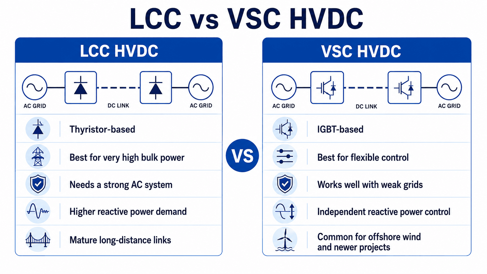
The converter technology is one of the most important technical choices in an HVDC system. Traditional line-commutated converter systems and newer voltage-source converter systems both transmit high-power DC, but they behave differently at the AC grid interface.
Line-commutated converter HVDC
LCC HVDC uses thyristor-based converters that depend on the connected AC system for commutation. It is mature, proven at very high power, and widely used for long-distance bulk transmission. The tradeoff is that LCC systems generally need a sufficiently strong AC system, consume reactive power, and require substantial filtering and reactive compensation.
Voltage-source converter HVDC
VSC HVDC uses self-commutated power electronic converters, commonly based on IGBT technology or related semiconductor switching devices. Many modern VSC-HVDC projects use modular multilevel converter architecture, where many submodules are stacked to synthesize a high-quality AC waveform and improve controllability compared with older converter approaches.
VSC systems can independently control active and reactive power, support weaker AC systems more effectively, and are especially relevant for offshore wind connections, underground cable projects, black-start support concepts, and emerging multi-terminal DC networks.
Converter type is not just a manufacturer detail. It changes the grid studies, reactive power plan, protection philosophy, station footprint, AC fault behavior, dynamic model requirements, and how the project behaves during disturbances.
When HVDC systems make sense
HVDC is usually selected because it solves a specific transmission problem: moving power over a difficult distance, using a cable route where AC is inefficient, connecting grids that cannot be directly synchronized, or adding controllable transfer capacity between regions.
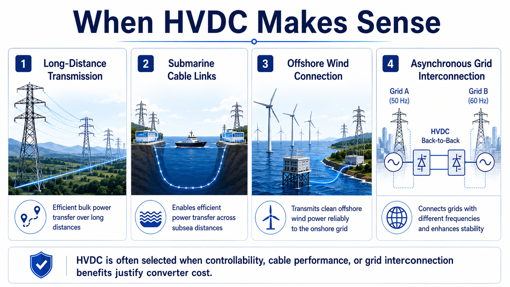
- Long-distance transmission: HVDC can transfer large power blocks over long corridors while avoiding some AC stability and reactive power limitations.
- Submarine cable links: HVDC is often used where AC cable charging current would limit practical transmission distance.
- Offshore wind connection: VSC HVDC is commonly evaluated for offshore wind export where distance, weak-grid behavior, and controllability matter.
- Asynchronous interconnection: Back-to-back HVDC can transfer power between AC systems that are not synchronized or do not operate at the same frequency.
HVDC losses and the basic engineering logic
HVDC efficiency is often explained through a simple relationship: for a given power transfer, increasing voltage reduces current. Lower current can reduce resistive losses in conductors, but the full project comparison must also include converter losses, filter losses, auxiliary station loads, and reliability requirements.
These equations explain why high voltage is useful for transmission. If the same power \(P\) is transferred at a higher voltage \(V\), the current \(I\) can be lower. Since conductor loss varies with the square of current, reducing current can significantly reduce line or cable loss.
- \(P\) Real power transfer, usually expressed in watts, megawatts, or gigawatts.
- \(V\) DC voltage level across the transmission link; higher voltage allows lower current for the same power.
- \(I\) DC current through the line or cable; current strongly affects conductor losses and thermal loading.
- \(R\) Total effective resistance of the DC path, including conductor length, material, temperature, and configuration effects.
The simplified loss logic is useful for first-pass understanding, but it should not be used alone to choose HVDC. A real comparison also considers converter station losses, power electronics cooling, redundancy, availability, spare equipment, cable thermal limits, system operating scenarios, and outage consequences.
HVDC application decision checklist
A strong HVDC screening process starts with the problem the grid is trying to solve. The checklist below is useful for early concept review before a detailed planning study, economic analysis, or interconnection study is performed.
Start with the transmission objective, identify whether the route is overhead, underground, or submarine, check whether the AC systems are synchronized, estimate the required MW transfer, evaluate converter station siting, then compare controllability, losses, protection complexity, and project cost against a practical HVAC alternative.
| HVDC screening check | What to look for | Why it matters |
|---|---|---|
| Long route with bulk transfer | High MW transfer over a long corridor, especially where AC stability or reactive power limits are important. | HVDC may provide controllable transfer capacity and lower total losses once terminal cost is justified. |
| Submarine or underground cable route | Long cable distance, constrained corridor, offshore generation, or water crossing. | DC cable operation can avoid the continuous charging-current limitation that makes long AC cable routes difficult. |
| Asynchronous AC systems | Two grids that cannot be directly tied with AC because of frequency, phase, operating area, or stability constraints. | HVDC can transfer power while electrically separating the AC systems. |
| Weak receiving grid or offshore source | Low short-circuit strength, remote renewable generation, or limited local voltage support. | VSC HVDC may provide better controllability and reactive power support than LCC in these conditions. |
| Converter station siting constraints | Available land, noise limits, access, cooling, AC switchyard interface, and environmental permitting. | Converter stations are not small substations; station layout can control feasibility even when the electrical case is strong. |
| Protection and outage strategy | DC fault clearing method, redundancy, bipole operation, spare transformers, valve modules, and restoration plan. | Reliability depends on how the system behaves when a converter, pole, cable, or protection element fails. |
Example: screening HVDC for an offshore wind export link
Consider a large offshore wind area located far from the onshore transmission grid. The export route is mostly submarine cable, the onshore grid needs a controllable power injection, and the offshore platform must operate with limited local short-circuit strength. This is a classic situation where VSC-HVDC may be evaluated.
Initial screening logic
The project team would first compare an AC export concept against an HVDC export concept. If the cable route is long enough for AC charging current to consume too much cable capacity or create voltage-control problems, HVDC becomes more attractive. If the offshore grid also needs flexible voltage and reactive power control, VSC-HVDC may be favored over LCC-HVDC.
What the screening does not prove
Early screening does not prove that HVDC is automatically economical. The final decision still depends on MW rating, export distance, converter station cost, offshore platform weight, cable repair strategy, environmental permits, grid-code requirements, loss evaluation, reliability targets, and the cost of realistic AC alternatives.
A strong HVDC screening result means the concept deserves detailed study. It does not replace load-flow studies, dynamic simulations, harmonic studies, insulation coordination, protection design, or a lifecycle cost comparison.
Common HVDC system configurations
HVDC systems can be arranged in several ways depending on power rating, reliability expectations, route constraints, grounding philosophy, and whether the project is a point-to-point link or part of a larger DC network.
| Configuration | How it works | Where it is useful |
|---|---|---|
| Monopolar HVDC | Uses one high-voltage pole with a return path through a metallic return conductor or, in some cases, ground or sea return. | Can be simpler, but return path choice affects environmental, corrosion, permitting, and reliability considerations. |
| Bipolar HVDC | Uses positive and negative poles, often allowing partial operation if one pole is out of service. | Common for high-capacity transmission where reliability and operational flexibility matter. |
| Back-to-back HVDC | Places rectifier and inverter functions at the same site with no long DC transmission route. | Useful for connecting asynchronous AC systems, controlling interchange, or separating grid disturbances. |
| Multi-terminal HVDC | Connects more than two converter stations through a DC network. | Relevant to future offshore wind hubs, regional DC grids, and controllable multi-node transmission systems. |
Multi-terminal HVDC and meshed DC grids are attractive in concept, but they make control coordination and DC fault protection more difficult. Point-to-point systems are simpler because the power path and protection zones are easier to define.
HVDC protection and DC fault behavior
Protection is one of the most important technical differences between HVDC and conventional AC transmission. AC current naturally crosses zero every half cycle, which helps breakers interrupt faults. DC current does not naturally cross zero, so DC fault interruption can require faster detection, converter blocking, specialized DC breakers, or other coordinated fault-clearing strategies.
| Protection issue | Why it is difficult in HVDC | Practical design concern |
|---|---|---|
| Fast DC fault-current rise | Low DC circuit impedance and converter controls can allow current to rise quickly after a pole or cable fault. | Protection must detect and isolate faults quickly enough to protect converters, cables, reactors, and arresters. |
| No natural current zero | Unlike AC, DC current does not naturally pass through zero during steady operation. | DC interruption may require specialized breaker technology, converter blocking, or line de-energization strategy. |
| Cable fault location and repair | Submarine and underground cable faults can be difficult to access, locate, and repair. | Availability studies must consider repair time, spare cable, vessel access, and outage impact. |
| Multi-terminal selectivity | More than two terminals create more possible fault paths and control interactions. | Selective isolation becomes harder than in a simple point-to-point HVDC link. |
| Converter control interaction | Protection actions and converter controls happen on fast timescales. | Dynamic models and hardware-specific data are needed to confirm stable and coordinated fault response. |
For this reason, HVDC protection is not just a relay setting exercise. It is a coordinated system design problem involving converter controls, DC yard equipment, AC protection, telecommunications, insulation coordination, operating procedures, and restoration planning.
HVDC misconceptions and better engineering interpretations
Many simplified HVDC explanations are directionally useful but incomplete. The table below reframes common statements into more useful engineering interpretations.
| Common misconception | Better engineering interpretation |
|---|---|
| HVDC is always more efficient than AC. | HVDC can reduce line or cable losses in the right application, but converter losses and station cost must be included. |
| HVDC is just a DC transmission line. | The complete system includes converter stations, controls, protection, filters, AC interfaces, and DC transmission equipment. |
| VSC HVDC is always better than LCC HVDC. | VSC is more flexible, but LCC can still be a strong choice for very high-power bulk transfer with strong AC systems. |
| There is one fixed HVDC break-even distance. | The crossover depends on route type, power rating, voltage, cable or line technology, converter cost, losses, and permitting constraints. |
| Back-to-back HVDC is only a small niche application. | Back-to-back HVDC can be strategically important where two AC systems need controlled power exchange without direct synchronization. |
Engineering Judgment and Field Reality
HVDC project decisions are rarely driven by one equation. A transmission planner may favor HVDC because it reduces the number of corridors needed, gives operators a controllable power injection, avoids a difficult AC stability problem, or allows an offshore wind area to connect to a distant load center. Those advantages must be weighed against converter station cost, specialized maintenance, outage exposure, vendor ecosystem, and grid-code requirements.
A clean one-line diagram can make HVDC look simple, but real projects depend on AC-grid strength, harmonic performance, control interactions, dynamic models, spare equipment strategy, and protection studies. The converter stations are often where project risk is concentrated.
Another practical issue is that HVDC is often evaluated where conventional AC solutions are politically or physically difficult. Underground or submarine HVDC may look attractive electrically, but permitting, cable thermal limits, landing points, repair access, and station siting can still control the final decision.
When This Breaks Down
Simplified HVDC explanations break down when they treat the DC link as an isolated wire rather than a controlled power electronic system connected to two AC networks. The converter, control system, and AC grid conditions determine whether the link operates reliably under real disturbances.
- Short routes with modest power transfer: Converter station cost and losses may outweigh any DC transmission benefit.
- Weak AC systems with the wrong converter choice: LCC systems can struggle without sufficient AC system strength, reactive support, and commutation margin.
- DC fault scenarios: DC faults can rise quickly and are harder to interrupt than AC faults because there is no natural current zero crossing.
- Overly simple loss comparisons: Line loss alone can mislead if converter losses, auxiliary loads, availability, cable ratings, and outage consequences are ignored.
- Modeling gaps: Inadequate dynamic models can miss converter control interactions, harmonic issues, weak-grid behavior, and ride-through performance.
Common mistakes and practical checks
The most common HVDC mistakes come from treating it as a universal upgrade over AC or from ignoring the support systems that make the converter stations work correctly.
- Calling HVDC “lossless”: HVDC can reduce transmission losses in the right case, but converters, filters, cooling, and auxiliary loads still consume power.
- Using a fixed break-even distance: The economic crossover depends on route type, voltage, power rating, cable technology, converter cost, permitting, and reliability criteria.
- Ignoring AC system strength: Converter behavior depends on the connected AC networks, especially for LCC systems and weak receiving grids.
- Underestimating protection complexity: DC faults and converter blocking sequences require specialized protection philosophy and coordinated controls.
- Forgetting operations and maintenance: Spare converter modules, transformer logistics, valve cooling, controls support, and outage planning can shape lifecycle cost.
Do not justify HVDC only by saying it is efficient over long distances. The stronger engineering case explains why DC solves a specific transmission problem better than a realistic AC alternative.
Engineering references and design guidance
HVDC projects require project-specific studies, utility interconnection requirements, manufacturer models, grid-code criteria, and detailed protection and control reviews. Public overview references are useful for understanding why HVDC is used, but detailed designs are governed by project documents and specialized technical standards.
- U.S. Department of Energy: Connecting the Country with HVDC provides a high-level explanation of why HVDC is useful for long-distance transmission, asynchronous interconnections, and modern grid expansion.
- Project-specific criteria: Owner requirements, grid operator interconnection rules, environmental constraints, cable route studies, and converter vendor data often control the final design.
- Engineering use: Planners use references and project criteria to screen HVDC feasibility, compare AC alternatives, define converter requirements, validate models, and review protection and control performance.
Frequently Asked Questions
An HVDC system is a high-voltage direct current transmission system that moves bulk electric power using DC instead of AC. It normally includes a sending-end converter station, a DC overhead line or cable, and a receiving-end converter station that reconnects the power to an AC grid.
HVDC is often used when long-distance transfer, submarine or underground cables, controllable power flow, or asynchronous grid interconnection justify the converter station cost. HVAC is still common for conventional transmission corridors, but HVDC can solve problems that AC transmission handles poorly.
LCC HVDC uses line-commutated thyristor converters and is often suited to very high-power bulk transfer where strong AC systems are available. VSC HVDC uses self-commutated power electronics, commonly IGBT-based or modular multilevel converter designs, and is better suited to flexible control, weak grids, offshore wind, and newer multi-terminal concepts.
No. HVDC can reduce line or cable losses in the right application, but converter stations add cost, losses, controls, protection, and maintenance complexity. The engineering question is not whether HVDC is always better, but whether its system-level benefits outweigh its terminal cost and complexity.
Summary and Next Steps
HVDC systems transmit bulk power using high-voltage direct current and converter stations that interface with AC grids. They are most useful where DC transmission solves a system-level problem: long-distance transfer, submarine or underground cable performance, offshore wind integration, asynchronous grid connection, or controllable regional power exchange.
The practical engineering review should consider converter technology, AC grid strength, line or cable rating, losses, DC fault protection, harmonic control, station siting, and lifecycle maintenance. HVDC is powerful, but it is not a default replacement for HVAC transmission.
Where to go next
Continue your learning path with related Turn2Engineering resources.
-
Transmission Line Protection
Learn how high-voltage transmission circuits are protected and why fault-clearing philosophy matters for grid reliability.
-
Voltage Regulation
Connect HVDC grid-interface behavior to the broader challenge of maintaining acceptable voltage under changing load and generation.
-
Protective Relays
Review the protection devices and logic used to detect abnormal power-system conditions and support reliable operation.