Key Takeaways
- Highway design is more than road layout: It combines design speed, alignment, sight distance, cross-sections, drainage, roadside safety, intersections, traffic operations, and constructability.
- Geometry controls driver expectation: Curves, grades, lane widths, medians, shoulders, signs, and roadside features should work together so the road feels predictable at the intended speed.
- Sight distance is a core safety check: Stopping sight distance, passing sight distance, and intersection sight distance help ensure drivers have enough time and space to react.
- Design standards matter: Highway design is usually governed by AASHTO, FHWA, MUTCD, state DOT manuals, municipal standards, and project-specific design criteria.
Table of Contents
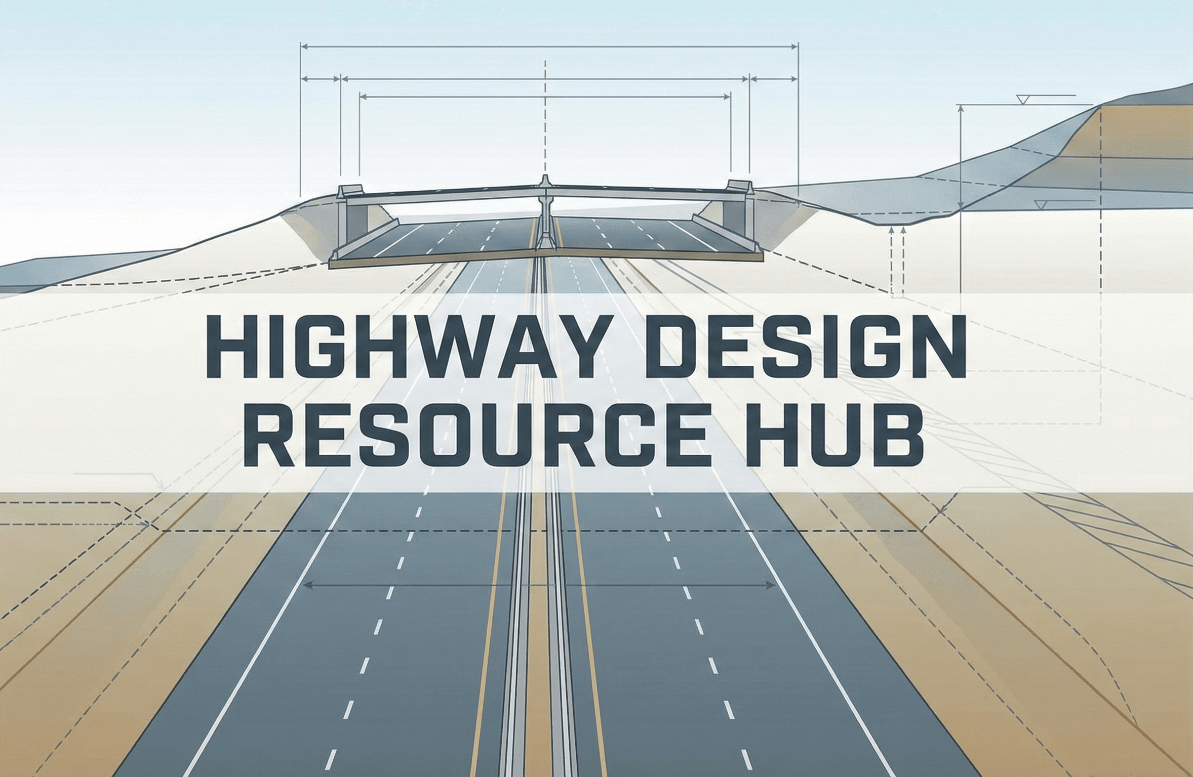
Featured diagram
Introduction
Highway design is where transportation engineering becomes visible. It turns traffic demand, safety goals, design standards, environmental constraints, right-of-way limits, drainage needs, and construction requirements into a physical roadway that drivers experience every day.
A well-designed highway feels predictable and forgiving. Curves match driver expectations, grades are manageable, sight lines are clear, roadside hazards are controlled, and drainage works without creating unsafe slopes or hidden conflicts. A poorly coordinated design can feel confusing, uncomfortable, or unsafe even when individual plan elements appear correct in isolation.
This guide explains the major parts of highway design: design speed, geometric design, sight distance, horizontal curves, vertical alignment, cross-sections, intersections, interchanges, roadside safety, drainage, pavement coordination, and the standards used on real projects.
What is highway design?
Direct answer: Highway design is the engineering process of laying out the physical geometry and roadside features of a roadway so it safely and efficiently serves its intended users. It includes design speed, horizontal and vertical alignment, sight distance, lane and shoulder widths, medians, intersections, interchanges, drainage, roadside safety, and traffic-control coordination.
The final product is not just a line on a map. A complete highway design includes plan and profile geometry, typical sections, pavement limits, cross slopes, drainage layout, grading, roadside safety features, traffic-control coordination, design exceptions if needed, and construction details.
Good highway design is internally consistent. The design speed, curve radii, grades, lane widths, shoulder widths, sight distance, signing, drainage, and roadside environment should all support the same operating expectation.
Highway design inputs checklist
Before designing curves, grades, cross-sections, or intersections, engineers need the project inputs that control the roadway geometry. These inputs define how the highway should operate, who it serves, what design standard governs, and what physical constraints limit the solution.
| Input | What it controls | Typical source | Why it matters |
|---|---|---|---|
| Functional classification | Freeway, arterial, collector, local road, rural highway, or urban corridor | State DOT, city, MPO, or roadway inventory | Sets design expectations for speed, access, mobility, and cross-section |
| Project context | Rural, suburban, urban, constrained, mountainous, industrial, or multimodal | Field review, planning study, local standards | Determines whether the design should prioritize speed, access, safety, freight, pedestrians, or constrained retrofit needs |
| Design speed | Curve radii, sight distance, vertical curves, roadside design, and driver expectation | Governing design criteria and engineering judgment | One of the most important geometric controls in highway design |
| Posted speed / target speed | Traffic control, operations, safety, and design consistency | Speed studies, agency policy, local context | Should be compatible with the actual roadway environment and operating speeds |
| Design vehicle | Turning radii, lane widths, intersection layout, ramp terminals, and curb returns | Traffic study, freight route classification, agency standard | Controls whether trucks, buses, emergency vehicles, or passenger cars can maneuver safely |
| Traffic volume | Lane count, intersection control, ramp design, auxiliary lanes, and capacity needs | Traffic counts, forecasts, traffic impact studies | Connects highway design to traffic engineering and level-of-service analysis |
| Crash history | Safety countermeasures, curve improvements, access changes, and roadside treatments | Crash database, safety study, road safety audit | Identifies locations where geometric design should solve an existing safety problem |
| Terrain | Grades, vertical curves, earthwork, drainage, and design exceptions | Survey, LiDAR, topographic mapping | Steep or rolling terrain can control alignment and cost |
| Right-of-way | Lane widening, shoulders, slopes, drainage, clear zone, sidewalks, and utilities | Survey, property records, project limits | Constrained right-of-way often drives design tradeoffs |
| Drainage constraints | Ditches, inlets, culverts, bridge openings, cross slope, and superelevation runoff | Hydrology study, drainage report, field review | Drainage must work without creating roadside or pavement problems |
| Utilities and structures | Profile grade, retaining walls, bridge clearances, utility relocations, and staging | Utility survey, bridge plans, SUE investigation | Late utility or structure conflicts can cause major redesigns |
| Pedestrian, bicycle, and transit needs | Sidewalks, bike lanes, shoulders, crossings, bus stops, refuge islands, and accessibility | Planning study, local policy, ADA review, public input | Many highways also function as urban arterials or community corridors |
A highway design that ignores context can technically meet a table value and still perform poorly. Always connect the design criteria to actual user behavior, land use, access patterns, freight movement, and roadside conditions.
Design speed, posted speed, operating speed, and target speed
Speed is one of the most important—and most misunderstood—controls in highway design. Designers use speed to select sight distance, curve radii, superelevation, vertical curve length, roadside features, and design consistency checks. But not every speed term means the same thing.
| Speed type | Meaning | Who controls it | Why it matters |
|---|---|---|---|
| Design speed | Selected speed used to determine geometric design criteria | Designer / agency criteria | Controls sight distance, curve radius, vertical curves, and roadside design assumptions |
| Posted speed | Legal speed limit shown to drivers | Agency / jurisdiction | Should be credible and consistent with the roadway environment |
| Operating speed | Speed drivers actually choose under prevailing conditions | Drivers responding to roadway context | Can reveal whether geometry encourages speeds higher than intended |
| Target speed | Desired operating speed for the roadway context | Planner / designer / agency policy | Useful in urban and context-sensitive designs where lower speeds are part of the safety goal |
| Advisory speed | Recommended speed for a curve, ramp, or condition | Traffic engineering study / agency practice | Warns drivers when a specific feature should be driven below the posted speed |
Do not assume the posted speed automatically equals the design speed. A roadway can be posted at one speed while drivers operate faster or slower depending on lane width, roadside openness, curvature, traffic control, access density, and enforcement.
Main elements of highway geometric design
Highway geometric design is the coordinated layout of the roadway in plan view, profile view, and cross-section. Each element affects safety, comfort, capacity, drainage, constructability, and driver expectations.
| Design element | What it controls | Common checks | Design risk if missed |
|---|---|---|---|
| Horizontal alignment | Tangents, curves, radii, transitions, and route layout | Minimum radius, superelevation, side friction, sight distance | Tight or inconsistent curves can surprise drivers |
| Vertical alignment | Grades, crest curves, sag curves, and profile elevations | Stopping sight distance, headlight sight distance, drainage, truck performance | Steep grades or short curves can limit visibility and operations |
| Cross-section | Lanes, shoulders, medians, slopes, curbs, ditches, and sidewalks | Lane width, shoulder width, clear zone, drainage, multimodal needs | Constrained sections can create operational and safety issues |
| Sight distance | Driver visibility along the roadway and at intersections | Stopping, passing, decision, and intersection sight distance | Drivers may not have enough time to react |
| Intersections | Turning movements, control type, storage, tapers, and sight triangles | Turn-lane length, design vehicle, skew, visibility, grades | Crashes, queues, and truck off-tracking can occur |
| Interchanges and ramps | Freeway access, merge/diverge areas, weaving, ramp terminals | Ramp design speed, acceleration/deceleration length, sight distance | Unsafe merges, short queues, or confusing decision points |
| Roadside safety | Clear zones, slopes, barriers, fixed objects, and end treatments | Recoverable area, barrier need, object setback, slope steepness | Run-off-road crashes can become more severe |
| Drainage coordination | Cross slope, ditches, inlets, culverts, bridge openings, and runoff path | Spread, gutter flow, ditch capacity, low points, erosion | Water can pond, damage pavement, or create hazards |
Stopping sight distance in highway design
Stopping sight distance is one of the core safety checks in highway design. It answers a simple question: if a driver sees an object or hazard in the lane, is there enough distance to perceive it, react, brake, and stop?
- \(SSD\) Stopping sight distance, usually in meters or feet
- \(V\) Vehicle speed, commonly converted to m/s in SI calculations
- \(t\) Perception-reaction time, often taken as 2.5 seconds in many design contexts
- \(g\) Acceleration due to gravity, approximately \(9.81\,m/s^2\)
- \(f\) Longitudinal friction factor between tires and pavement
- \(G\) Roadway grade as a decimal; positive for upgrades and negative for downgrades
The first part, \(Vt\), is the distance traveled while the driver perceives the hazard and reacts. The second part, \(\frac{V^2}{2g(f+G)}\), is the braking distance. Because speed is squared in the braking term, stopping distance grows quickly as speed increases.
Other sight distance checks
- Passing sight distance: needed on two-lane highways where passing maneuvers are allowed.
- Decision sight distance: useful where drivers need more time to detect, interpret, and respond to complex conditions.
- Intersection sight distance: needed for drivers entering, crossing, or turning at intersections and driveways.
- Horizontal curve sight distance: affected by barriers, cut slopes, vegetation, bridge rails, and inside-curve obstructions.
- Vertical curve sight distance: affected by crest curves, sag curves, headlights, and driver eye/object height assumptions.
Sight distance is not just an equation. Field obstructions such as bridge piers, signs, vegetation, walls, barriers, and cut slopes can reduce the actual visible distance even when the plan geometry appears acceptable.
Worked example: stopping sight distance
Example
Suppose you are checking a rural highway with a design speed of \(90\,km/h\) on a level grade. Use \(t=2.5\,s\), \(f=0.35\), \(G=0\), and \(g=9.81\,m/s^2\).
Convert speed: \(90\,km/h = 25\,m/s\).
Step 1: perception-reaction distance
Step 2: braking distance
Step 3: total stopping sight distance
The roadway should provide at least about \(154\,m\) of stopping sight distance under these assumptions. A real design should compare this against the governing standard and applicable design tables.
Horizontal alignment and curve design
Horizontal alignment is the plan-view layout of the highway. It includes tangents, circular curves, compound curves, reverse curves, spiral transitions, and the way the road fits the terrain and right-of-way.
The key challenge is matching curve geometry to driver expectation. A highway should not abruptly transition from long, high-speed tangents to unexpectedly tight curves. Consistency matters because drivers tend to choose speed based on the visual roadway environment.
Minimum curve radius concept
For a vehicle traveling around a horizontal curve, lateral acceleration is resisted by roadway superelevation and tire-pavement side friction. A simplified relationship is:
- \(R\) Curve radius
- \(V\) Vehicle speed in consistent units, such as m/s for SI
- \(g\) Acceleration due to gravity
- \(e\) Superelevation rate as a decimal
- \(f_s\) Side friction factor
Superelevation
Superelevation is the rotation of the roadway cross-section on a horizontal curve. It helps vehicles negotiate curves by banking the pavement toward the inside of the curve. Superelevation design must also consider drainage, snow/ice climate, adjacent intersections, driveways, bridges, and transition length.
A curve radius may meet a minimum table value but still feel uncomfortable if the approach geometry, transition, roadside environment, or superelevation runoff is inconsistent with driver expectations.
Worked example: horizontal curve radius
Suppose a highway curve is being checked for a design speed of \(80\,km/h\). Assume \(e=0.06\), \(f_s=0.12\), and \(g=9.81\,m/s^2\). Convert \(80\,km/h\) to \(22.2\,m/s\).
This simplified check suggests a curve radius of about \(279\,m\) under the assumed speed, superelevation, and side-friction values. In practice, the governing design manual should be used for final values because agencies specify allowable superelevation, side friction, transition length, and design controls.
Vertical alignment, grades, and vertical curves
Vertical alignment is the profile of the highway along its centerline or profile grade line. It includes tangent grades, crest vertical curves, sag vertical curves, bridge clearances, drainage low points, and grade transitions.
Crest vertical curves
Crest vertical curves occur where an upgrade transitions to a flatter grade or downgrade. They are commonly controlled by stopping sight distance because the pavement surface can block the driver’s view of an object beyond the crest.
Sag vertical curves
Sag vertical curves occur where a downgrade transitions to a flatter grade or upgrade. They are often controlled by headlight sight distance, drainage at the low point, comfort, and vertical clearance under structures.
Grades and truck performance
Long or steep grades can reduce truck speeds, increase braking demand, affect capacity, and require climbing lanes, runaway truck ramps, or special operational treatments. Highway design should evaluate whether grades are compatible with design vehicle performance and traffic operations.
| Vertical design issue | Why it matters | Common design check |
|---|---|---|
| Crest vertical curve | Can limit driver visibility over the top of the curve | Stopping sight distance |
| Sag vertical curve | Can affect nighttime headlight sight distance and drainage | Headlight sight distance, drainage, comfort |
| Steep upgrade | Can slow heavy vehicles and reduce capacity | Truck speed profile and climbing lane need |
| Steep downgrade | Increases braking demand and stopping distance | SSD on downgrade, runaway truck risk, speed management |
| Low point drainage | Can create ponding and hydroplaning risk | Inlet placement, spread, sag drainage capacity |
Horizontal and vertical alignment should be reviewed together. A sharp horizontal curve hidden beyond a crest vertical curve is a classic design consistency problem.
Highway cross-section design
The highway cross-section is the slice across the roadway. It controls how much space is provided for vehicles, drainage, recovery, barriers, pedestrians, cyclists, utilities, shoulders, medians, and side slopes.
| Cross-section element | Purpose | Design considerations |
|---|---|---|
| Travel lanes | Provide vehicle operating space | Lane width depends on speed, context, traffic mix, trucks, and agency criteria |
| Shoulders | Provide recovery space, breakdown area, structural support, and emergency access | Width varies by facility type, traffic volume, speed, and roadside constraints |
| Medians | Separate opposing traffic and provide recovery or barrier space | Can be flush, raised, depressed, or barrier-separated |
| Cross slope | Moves water off the pavement surface | Must balance drainage, comfort, accessibility, and superelevation transitions |
| Side slopes | Connect roadway elevation to existing ground or ditches | Recoverability and stability matter for roadside safety |
| Ditches and drainage features | Collect and convey runoff | Need hydraulic capacity without creating unsafe roadside geometry |
| Clear zone | Provides recoverable space for vehicles that leave the roadway | Depends on speed, volume, slope, curvature, and roadside hazards |
| Barriers | Shield hazards when removal or clear-zone recovery is not practical | Should only be used where striking the barrier is less severe than striking the hazard |
Cross-section design is where safety, drainage, constructability, and right-of-way constraints collide. A section that works geometrically may still fail if it cannot drain, be maintained, or fit within the available property.
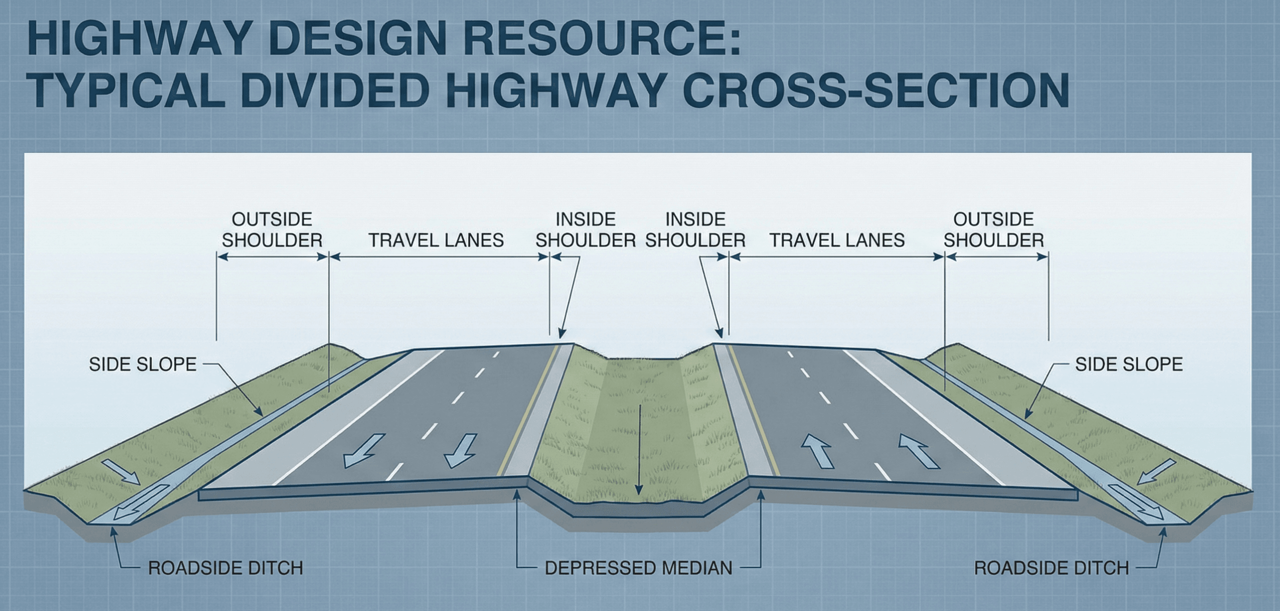
Visualizing a typical highway cross-section
It is often easier to understand highway design by looking at a cross-section slice rather than only a plan view. A typical section shows lanes, shoulders, medians, side slopes, ditches, and clear zones at once.
Intersections, interchanges, ramps, and access management
Highway design does not stop at the mainline. Intersections, ramps, driveways, and access points often create the highest conflict areas on a corridor. Their design affects crashes, delay, freight movement, pedestrian crossings, and the driver’s ability to make decisions in time.
Intersection design elements
- Turn lanes: separate turning traffic from through traffic and reduce rear-end crash risk.
- Storage length: provides queue space so turning vehicles do not block through lanes.
- Tapers: transition vehicles into turn lanes or lane drops gradually.
- Corner radii: accommodate the design vehicle without encouraging unnecessarily high turning speeds.
- Sight triangles: preserve visibility for drivers entering, crossing, or turning.
- Grades: should support stopping, acceleration, drainage, and accessibility where applicable.
Ramp and interchange design elements
- Ramp design speed: should be compatible with curvature, grade, and driver expectations.
- Acceleration and deceleration lanes: provide space for speed change outside the through lanes.
- Merge and diverge areas: should be long enough and visible enough for safe lane changes.
- Weaving sections: require special attention where entering and exiting traffic cross paths.
- Ramp terminals: should clearly communicate right-of-way, storage, lane assignments, and turning paths.
A mainline highway can be geometrically sound while its ramp terminal or nearby driveway spacing creates operational and safety problems. Always review access points as part of the highway design system.
Roadside safety and clear zones
Roadside safety focuses on what happens when a vehicle leaves the traveled way. The design goal is to provide a forgiving roadside where possible and to shield hazards only when removing or relocating them is not practical.
Roadside safety priorities
- Remove the hazard if it is not needed.
- Relocate the hazard farther from traffic if removal is not practical.
- Make the hazard breakaway or traversable where feasible.
- Shield the hazard with a barrier if the hazard cannot be removed, relocated, or made safer.
| Roadside element | Design concern | Typical response |
|---|---|---|
| Steep side slope | Vehicle rollover or loss of control | Flatten slope, provide recovery area, or shield if needed |
| Fixed object | Severe impact risk | Remove, relocate, make breakaway, or shield |
| Bridge pier or abutment | Rigid obstacle near traffic | Use barrier, crash cushion, or geometric relocation where feasible |
| Drainage structure | Headwall, culvert end, steep ditch, or drop-off hazard | Use traversable end treatment, flattening, relocation, or barrier |
| Barrier end | Impact severity if untreated | Use approved end treatment or crash cushion |
Drainage and pavement coordination in highway design
Highway design must coordinate with drainage and pavement design. The roadway geometry controls where water flows, how quickly it leaves the surface, where ditches and inlets fit, and whether the pavement structure remains protected from moisture damage.
Key drainage coordination points
- Cross slope: moves water off travel lanes and shoulders.
- Superelevation runoff: transitions pavement slope on curves without creating awkward drainage or driver-comfort issues.
- Sag vertical curves: require careful inlet placement because water collects at low points.
- Ditches: must carry runoff while maintaining safe side slopes and erosion control.
- Culverts and bridges: must fit the profile, hydraulic opening, and roadway safety needs.
- Pavement edges: should drain without trapping water in the pavement structure.
Review every low point in profile and every superelevation transition in plan. These are common places where drainage, pavement, and geometry conflict.
For more detail on pavement structure, layer thickness, traffic loading, and subgrade support, see the related guide on Pavement Design.
Common highway design mistakes and review checks
Many highway design problems come from coordination gaps rather than a single incorrect equation. Use the table below as a practical review checklist.
| Common issue | Why it matters | Review check |
|---|---|---|
| Design speed does not match operating speed | Drivers may travel faster than the geometry safely supports | Compare design speed, posted speed, operating speed, context, and curve consistency |
| Insufficient sight distance | Drivers may not have enough time to stop or make decisions | Check SSD, intersection sight distance, and obstructions in both directions |
| Poor horizontal/vertical coordination | Curves, grades, and visibility may combine in unexpected ways | Review plan and profile together, not separately |
| Bad superelevation transition | Can create drainage, comfort, and control issues | Check runoff length, low points, adjacent intersections, and bridge limits |
| Roadside hazards left untreated | Run-off-road crashes can become more severe | Review clear zone, fixed objects, slopes, and barrier warrants |
| Intersection storage too short | Queues can block through lanes or spill into upstream intersections | Check turn-lane storage, tapers, queue analysis, and signal operations |
| Drainage features conflict with safety | Ditches, headwalls, and inlets can become roadside hazards | Review ditch shape, culvert ends, slope recoverability, and barrier needs |
| Ignoring pedestrians, bikes, or transit in urban corridors | Highway-style geometry may conflict with urban access and safety needs | Review crossings, ADA needs, bus stops, bike accommodation, and context |
A strong review method is to “drive” the design mentally in both directions at the expected operating speed. Look for surprises: sudden curvature changes, hidden intersections, short decision zones, confusing ramp choices, awkward lane drops, and roadside obstacles.
Work with real numbers
Engineering calculators & equation hub
Jump from theory to practice with interactive calculators and equation summaries covering civil, mechanical, electrical, and transportation topics.
Key standards and design references for highway design
Highway design is heavily standards-driven. The correct design criteria depend on the project owner, jurisdiction, facility type, design speed, context, funding source, and whether the work is new construction, reconstruction, rehabilitation, or a constrained retrofit.
- AASHTO Green Book: The primary geometric design reference in many U.S. jurisdictions, covering design speed, sight distance, horizontal and vertical alignment, cross-section elements, intersections, and interchanges.
- FHWA geometric design and safety resources: FHWA publishes guidance related to speed, geometric design, roadside safety, design flexibility, and performance-based practical design. Review FHWA speed and geometric design concepts.
- Highway Capacity Manual: Used for analyzing capacity, level of service, traffic operations, freeways, multilane highways, intersections, ramps, and interchanges. Capacity results often influence lane count, intersection layout, and ramp design.
- Manual on Uniform Traffic Control Devices: Provides national guidance for signs, markings, signals, and traffic-control devices used with the physical highway design. Visit the official MUTCD site.
- State DOT roadway design manuals: State manuals often govern the actual design values used on projects, including cross-section criteria, superelevation, vertical alignment, clear zones, barriers, design exceptions, and plan requirements. See the TxDOT Roadway Design Manual.
- Local and municipal standards: City, county, and development standards may control urban arterials, subdivision roads, driveway access, utility restoration, sidewalk requirements, and curb-and-gutter sections.
Always identify the governing standard before final design. Educational equations and general rules of thumb should never override the project’s adopted state DOT, municipal, federal, airport, toll authority, or owner design criteria.
Frequently asked questions
Highway design is the engineering process of laying out the physical geometry and roadside features of a roadway so it safely and efficiently serves its intended users. It includes design speed, alignment, sight distance, cross-sections, intersections, interchanges, drainage, roadside safety, and traffic-control coordination.
Highway design focuses on the physical roadway geometry, while traffic engineering focuses on how people and vehicles move through the network. In practice, both disciplines work together because traffic volumes, speeds, turning movements, and control devices influence the highway geometry.
The main parts include design speed, horizontal alignment, vertical alignment, sight distance, lane width, shoulder width, medians, cross slopes, superelevation, intersections, ramps, drainage, clear zones, and roadside barriers.
Stopping sight distance is important because drivers need enough distance to see a hazard, react, brake, and stop. If the available sight distance is shorter than the required stopping distance, the roadway geometry may need to be adjusted or mitigated.
Common references include the AASHTO Green Book, FHWA geometric design and safety guidance, the Highway Capacity Manual, the Manual on Uniform Traffic Control Devices, and state or local roadway design manuals.
Summary and next steps
Highway design is the coordinated process of shaping the roadway so drivers and other users can move safely, comfortably, and efficiently. The most important controls include design speed, sight distance, horizontal alignment, vertical alignment, cross-section elements, intersections, roadside safety, drainage, and standards compliance.
The best highway designs are not just mathematically correct. They are consistent, readable, buildable, maintainable, and forgiving. A good designer reviews the road as a system: what drivers see, how they react, where water flows, how trucks move, where crashes could become severe, and how the design fits the surrounding context.
Where to go next
Continue your learning path with these transportation engineering resources.
-
Explore the Transportation Engineering hub
See the full transportation engineering topic library, including planning, traffic flow, pavement, safety, and public transportation.
-
Read the guide on Pavement Design
Learn how traffic loading, subgrade support, drainage, and materials are used to determine pavement layer thickness.
-
Learn about Traffic Flow Theory
Understand how speed, flow, and density influence roadway capacity, lane counts, operations, and design decisions.
-
Read the guide on Transportation Planning
See how long-range planning, demand forecasting, and corridor selection feed into highway design.