Key Takeaways
- Core idea: Shell structures are thin curved surfaces that carry load primarily through in-plane membrane forces rather than bending alone.
- Engineering use: They are used for domes, vaults, canopies, tanks, silos, stadium roofs, gridshells, and long-span architectural enclosures.
- What controls it: Geometry, curvature, thickness, support restraint, edge beams, openings, loading pattern, material behavior, and construction tolerance control performance.
- Practical check: The most important shell design question is whether the chosen form actually supports the intended load path without excessive bending, buckling, or edge distress.
Table of Contents
Introduction
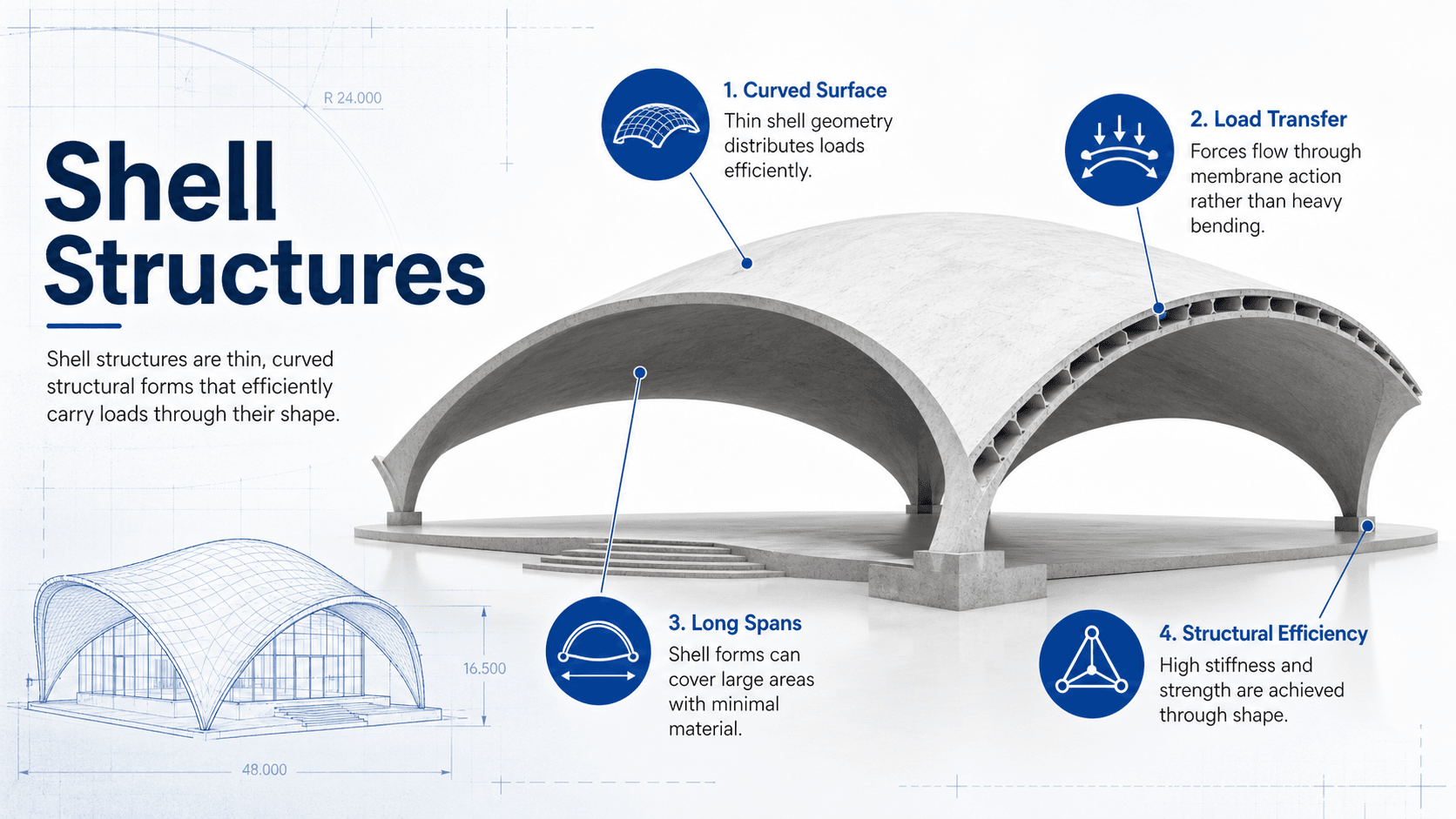
Shell structures are thin, curved structural surfaces that carry loads mainly through in-plane compression, tension, and shear. Their strength comes from geometry: when the form aligns with the load path, a shell can span large areas with relatively little material while creating open, expressive spaces.
How Shell Structures Carry Loads
Notice that the shell shape is not just architectural. The curvature changes how gravity, wind, uplift, and support reactions flow through the structure. A good shell reduces bending by keeping forces in the surface as much as possible.
What Is a Shell Structure?
A shell structure is a three-dimensional structural surface with a thickness that is small compared with its span and plan dimensions. Unlike a beam, which primarily resists bending along a line, or a flat plate, which bends over an area, a shell uses curvature to develop membrane forces across the surface.
In structural engineering, the value of a shell is not simply that it is thin. The important feature is that its shape helps the load find an efficient path. A dome, for example, can direct gravity loads downward through meridional compression and hoop action, while a saddle-shaped shell can develop crossing tension and compression fields.
A shell works best when geometry, load direction, support layout, and material behavior all agree. If one of those changes, the shell may stop behaving like an efficient membrane and start behaving like a thin, bending-sensitive plate.
Main Types of Shell Structures
Shell structures are usually grouped by curvature, construction method, and structural action. The type matters because each shape creates a different force pattern, different support demand, and different construction challenge.
| Shell type | Typical shape | Common use | Engineering behavior |
|---|---|---|---|
| Dome shell | Positive double curvature | Arenas, tanks, observatories, circular roofs | Efficient under symmetric gravity loads; ring tension or compression at the base may control detailing. |
| Barrel vault | Single curvature | Long roofs, terminals, industrial buildings | Acts like a curved surface spanning between supports; edge beams and diaphragms often control performance. |
| Hyperbolic paraboloid shell | Negative double curvature | Canopies, roofs, pavilions | Develops crossing tension and compression fields and can often be formed from straight generative lines. |
| Folded plate shell | Faceted plates | Roof systems, industrial structures, long-span covers | Uses folds to create stiffness; easier to form than continuous curved shells. |
| Gridshell | Curved lattice | Atriums, museums, timber or steel roofs | Uses a network of members following a curved surface; member buckling and joint stiffness are critical. |
| Free-form shell | Irregular curved surface | Modern architecture, landmark roofs | Requires careful modeling because local curvature and support stiffness can change force flow dramatically. |
How Shell Structures Work
Shell structures work by moving load through a curved surface. In an ideal shell, much of the load is resisted by membrane action: compression, tension, and shear acting within the surface. Bending still exists, especially near edges, openings, point loads, and support discontinuities, but the goal is to keep bending from becoming the dominant behavior.
Membrane action
Membrane action is the efficient part of shell behavior. Instead of the shell bending like a flat slab, the surface develops in-plane force resultants. These forces are usually expressed per unit length of shell surface.
- N Membrane force resultant, commonly in lb/ft, kip/ft, N/m, or kN/m depending on the design system.
- M Bending moment per unit length, important near edges, penetrations, concentrated loads, and local discontinuities.
- κ Curvature of the shell surface; the geometry that helps redirect load through the surface.
Curvature and force flow
Curvature is what separates a shell from a flat plate. A dome, barrel vault, and saddle shell may all be thin surfaces, but they do not carry load in the same way. Positive double curvature, negative double curvature, and single curvature each create different support reactions and stress patterns.
In this simplified curvature relationship, \(K\) is Gaussian curvature and \(\kappa_1\) and \(\kappa_2\) are the principal curvatures. A dome has positive Gaussian curvature, a saddle shell has negative Gaussian curvature, and a barrel vault has one main curvature direction.
Edges, supports, and rings
Edges are often where shell behavior becomes less ideal. A free edge, stiff ring beam, discrete column support, or restrained boundary can introduce bending, torsion, cracking, local buckling, or concentrated reactions. In many shell designs, the edge system is just as important as the shell surface itself.
Where Shell Structures Are Used
Shell structures are selected when engineers and architects need long spans, column-free space, efficient enclosure, or expressive geometry. They are common in both building structures and civil infrastructure.
- Domes and arena roofs: large-span enclosures where loads can flow toward a continuous perimeter ring.
- Barrel vaults: long roofs for halls, terminals, warehouses, and industrial buildings.
- Hypar canopies: lightweight pavilions, plazas, covered walkways, and architectural roof forms.
- Tanks, silos, and reservoirs: thin curved walls where hoop forces and membrane action are central to performance.
- Gridshells: steel or timber lattice systems for atriums, museums, courtyards, and long-span glazed roofs.
- Folded plates: roof systems where faceted geometry provides depth and stiffness without a conventional truss profile.
If the shell requires many heavy secondary beams to work, the form may not be doing enough structural work. A strong concept study compares shell action, support reactions, constructability, and total system weight before committing to the final geometry.
What Controls Shell Structure Design?
Shell design is controlled by more than material strength. Geometry, boundary conditions, stiffness, stability, construction tolerances, and durability can control the final design even when the shell surface looks simple.
| Factor | Why it matters | Engineering implication |
|---|---|---|
| Curvature | Curvature determines whether the shell can carry load through membrane action. | Small geometry changes can shift a shell from compression-dominant behavior to bending-sensitive behavior. |
| Support layout | Continuous supports, discrete columns, rings, and edge beams create different stress concentrations. | Edge design often controls cracking, anchorage, thrust, and local bending. |
| Thickness-to-span ratio | Thin shells are efficient but more vulnerable to buckling and construction imperfections. | Stability checks and minimum practical thickness may control over strength alone. |
| Openings and penetrations | Skylights, drains, ducts, and access hatches interrupt membrane force paths. | Openings usually need local frames, thickened zones, or reinforcement around the perimeter. |
| Loading pattern | Uniform gravity load, wind suction, seismic inertia, thermal movement, and construction loads do not produce the same force pattern. | Asymmetric loads can create bending and torsion that are hidden in simplified diagrams. |
| Construction tolerance | A shell relies on shape, so deviations from the intended geometry can change force flow. | Survey control, formwork stiffness, panel fit-up, and as-built verification are part of structural performance. |
Shell Structure Design Workflow
A shell structure is usually designed through an iterative process. Engineers begin with the intended architectural form, test whether the geometry creates a rational load path, then refine thickness, reinforcement, members, edge details, and support conditions.
- Define the performance goal: span, use, enclosure, durability, exposure, fire rating, deflection limits, and architectural constraints.
- Select the shell type: dome, barrel vault, folded plate, gridshell, hypar, or free-form shell based on the load path and buildability.
- Establish loads: dead load, live load, snow, wind, seismic, thermal effects, construction loading, maintenance loading, and local equipment loads.
- Model membrane and bending behavior: use shell finite element modeling where appropriate and review results for force flow, edge effects, and local stress concentrations.
- Check stability: evaluate buckling, imperfections, support movement, and compression zones.
- Detail boundaries and openings: design ring beams, edge beams, ribs, collectors, anchorage, reinforcement, and penetration frames.
- Review constructability: verify formwork, panelization, lifting, survey tolerance, sequencing, waterproofing, and inspection access.
In early design, do not only ask “is the shell strong enough?” Ask whether the load path is clean, whether the supports can resolve thrust, whether openings interrupt the force flow, and whether the selected shape can actually be built within tolerance.
Shell Structure Design Review Checklist
Use this checklist as a practical review tool when evaluating a shell concept, early model, or preliminary design package. It is not a substitute for project-specific analysis, but it helps identify the issues that commonly control shell performance.
Start with the intended shape → trace the gravity and lateral load paths → identify where membrane action is likely and where bending will occur → review supports and edges → check openings and concentrated loads → test stability and imperfections → confirm the geometry can be built and inspected.
| Check or decision | What to look for | Why it matters |
|---|---|---|
| Load path clarity | Forces should flow through the curved surface toward supports without relying on hidden bending resistance. | A shell that cannot explain its own force path is likely to need heavier ribs, beams, or local thickening. |
| Edge restraint | Review ring beams, edge beams, supports, bearings, anchors, and collectors. | Edges often control cracking, thrust, torsion, uplift, and local bending. |
| Buckling sensitivity | Compression zones, thin panels, imperfect geometry, and concentrated loads. | Thin shells can fail by instability before material strength is fully used. |
| Openings and penetrations | Skylights, roof drains, ducts, access panels, and mechanical supports. | Openings interrupt membrane flow and create local bending and stress concentrations. |
| Construction tolerance | Formwork accuracy, panel fit, survey points, joint alignment, and curing sequence. | Small shape deviations can create bending that the idealized model did not predict. |
| Durability and water control | Drainage, waterproofing, joints, sealants, cover, corrosion protection, and inspection access. | A shell roof that is structurally elegant can still fail as a building system if water management is poor. |
Example: Reading the Load Path in a Dome Shell
Consider a reinforced concrete dome roof over a circular tank or assembly space. Under nearly uniform gravity load, the shell surface tends to move load downward through meridional compression. Near the lower portion of the dome, hoop forces and support reactions become important.
What the engineer checks first
The engineer checks whether the dome has a reliable compression path, whether the base ring can resist the required hoop action, and whether the supports can accept horizontal thrust or are detailed to relieve movement. The shell surface may look thin, but the perimeter ring can be one of the most critical elements in the system.
How the interpretation changes
If the dome has a large skylight, discrete supports, heavy suspended equipment, or uneven wind pressure, the clean membrane picture changes. Local bending, stress concentrations, and serviceability checks become more important. The design must then treat the dome as a real shell with edge effects, not as an idealized diagram.
Engineering Judgment and Field Reality
In practice, shell structures rarely behave as perfectly as textbook membrane diagrams suggest. Real projects include construction joints, tolerances, reinforcement congestion, crane picks, formwork deflection, uneven curing, wind uplift, penetrations, and architectural changes that can add bending where the concept model assumed smooth force flow.
Experienced engineers pay close attention to the places where ideal shell theory meets construction reality: edges, supports, corners, openings, skylights, drains, anchor plates, joint lines, and interfaces with cladding or façade systems. These details may determine whether the structure performs cleanly or develops cracks, leaks, vibration, or local overstress.
A thin shell can be strong in the model and still be difficult in the field if the formwork cannot hold the intended curvature, the reinforcement cannot be placed cleanly, or the waterproofing cannot follow the geometry without weak points.
When This Breaks Down
The simplified idea that shells carry load mainly through membrane action becomes less reliable when the shell geometry, supports, loads, or construction details interrupt the intended force flow.
- Large openings: skylights, access hatches, and duct penetrations can cut through the membrane force path.
- Discrete supports: point supports can create local bending, punching-type effects, torsion, or concentrated reactions.
- Asymmetric loading: wind suction, seismic inertia, drifting snow, and partial live loading can create bending not present under uniform gravity load.
- Geometric imperfections: small deviations in thin shells can reduce buckling capacity and change stress distribution.
- Restrained movement: thermal expansion, shrinkage, creep, and support settlement can introduce unintended stress.
- Poor edge detailing: inadequate ring beams, weak anchorage, or discontinuous collectors can prevent the shell from resolving thrust correctly.
Common Mistakes and Practical Checks
Shell structures are often misunderstood because they look simple in diagrams. The common mistakes usually come from treating a shell as a decorative surface instead of a geometry-dependent structural system.
- Ignoring edge effects: assuming the shell surface controls while overlooking the ring beam, edge beam, or support restraint.
- Using a beautiful shape without a load path: selecting a free-form surface that creates high bending and local stress concentrations.
- Cutting openings late: adding skylights or penetrations after structural behavior has already been established.
- Underestimating buckling: checking strength but not stability, imperfections, or compression-sensitive zones.
- Separating structure from waterproofing: creating a curved roof that is structurally efficient but difficult to drain, seal, or maintain.
- Skipping construction sequencing: failing to check temporary load cases, formwork behavior, lifting, bracing, and partial-completion conditions.
The biggest mistake is assuming that a curved roof automatically behaves as an efficient shell. Curvature helps only when the support conditions, load pattern, and detailing allow membrane forces to develop.
Useful References and Design Context
Shell structures may involve concrete design, steel design, timber design, wind loading, seismic loading, buckling analysis, and specialty finite element modeling. The exact references depend on material, jurisdiction, and project type.
- ASCE/SEI 7: Used for minimum design loads such as wind, seismic, snow, rain, and load combinations that may govern shell roof systems.
- ACI 318 and concrete shell guidance: Relevant for reinforced concrete shells, reinforcement detailing, serviceability, strength, durability, and concrete behavior.
- AISC steel design resources: Relevant for steel gridshells, edge members, ribs, connections, compression members, and stability checks.
- National Design Specification for Wood Construction: Relevant for timber gridshell members, connections, and material-specific design checks.
- IASS shell and spatial structure research: Useful for deeper study of shells, gridshells, form finding, long-span roof systems, and spatial structural behavior.
Frequently Asked Questions
A shell structure is a thin, curved structural surface that carries loads mainly through in-plane compression, tension, and shear. Because the geometry helps direct forces through the surface, shells can span large areas with relatively little material when the shape, supports, and loading are compatible.
Common shell structure types include domes, barrel vaults, cylindrical shells, hyperbolic paraboloid shells, folded plates, gridshells, and free-form shells. The best type depends on span, load pattern, support layout, material, drainage, constructability, and architectural goals.
Shell structures are efficient because curvature allows loads to flow through the surface as membrane forces instead of relying only on bending. When the form follows the load path, the structure can achieve high stiffness and long spans with less material than a flat plate or conventional framed roof.
Shell structures can fail or perform poorly when buckling, edge restraint, cracking, poor support detailing, unplanned openings, construction tolerances, water intrusion, or local concentrated loads disrupt the intended membrane force path. Thin shells are especially sensitive to imperfections and boundary conditions.
Summary and Next Steps
Shell structures are thin curved surfaces that use geometry to carry load efficiently. Their value comes from membrane action, controlled curvature, and clean force flow from the surface into edges, supports, rings, ribs, and foundations.
A strong shell design is not only a strength check. It requires attention to curvature, edge conditions, openings, buckling, construction tolerance, waterproofing, and inspection access. The best shell systems align structural form, architectural intent, material selection, and constructability from the beginning.
Where to go next
Continue your learning path with related Turn2Engineering resources.
-
Structural Analysis
Learn how engineers model forces, reactions, stiffness, and load paths in structural systems.
-
Load Path Analysis
Shell structures depend on clear force flow, making load path analysis a critical next concept.
-
Structural Dynamics
Lightweight long-span shell roofs can be sensitive to vibration, wind response, and dynamic behavior.