Key Takeaways
- Definition: An isolated foundation is a discrete shallow footing that supports one column, pier, or concentrated load and spreads that load over a safe soil contact area.
- Use case: It is most useful when column loads are separated enough that individual footings remain simpler and more economical than combined or raft systems.
- Main decision: Good design is not just footing area. Engineers also check settlement, eccentricity, shear, bending, embedment, and actual founding conditions in the field.
- Outcome: After this page, you should be able to understand the logic behind isolated footing selection, sizing, and the conditions that push a project toward another foundation type.
Table of Contents
Introduction
In brief: Isolated foundations are single-column shallow footings that spread concentrated structural loads into near-surface soil while keeping bearing pressure and settlement within acceptable limits.
Who it’s for: Students, FE/PE prep, and foundation designers.
For informational purposes only. See Terms and Conditions.
In practice, isolated foundations are one of the simplest foundation systems to sketch but one of the easiest to misuse if the soil profile, load path, or field conditions are oversimplified.
Isolated foundations infographic
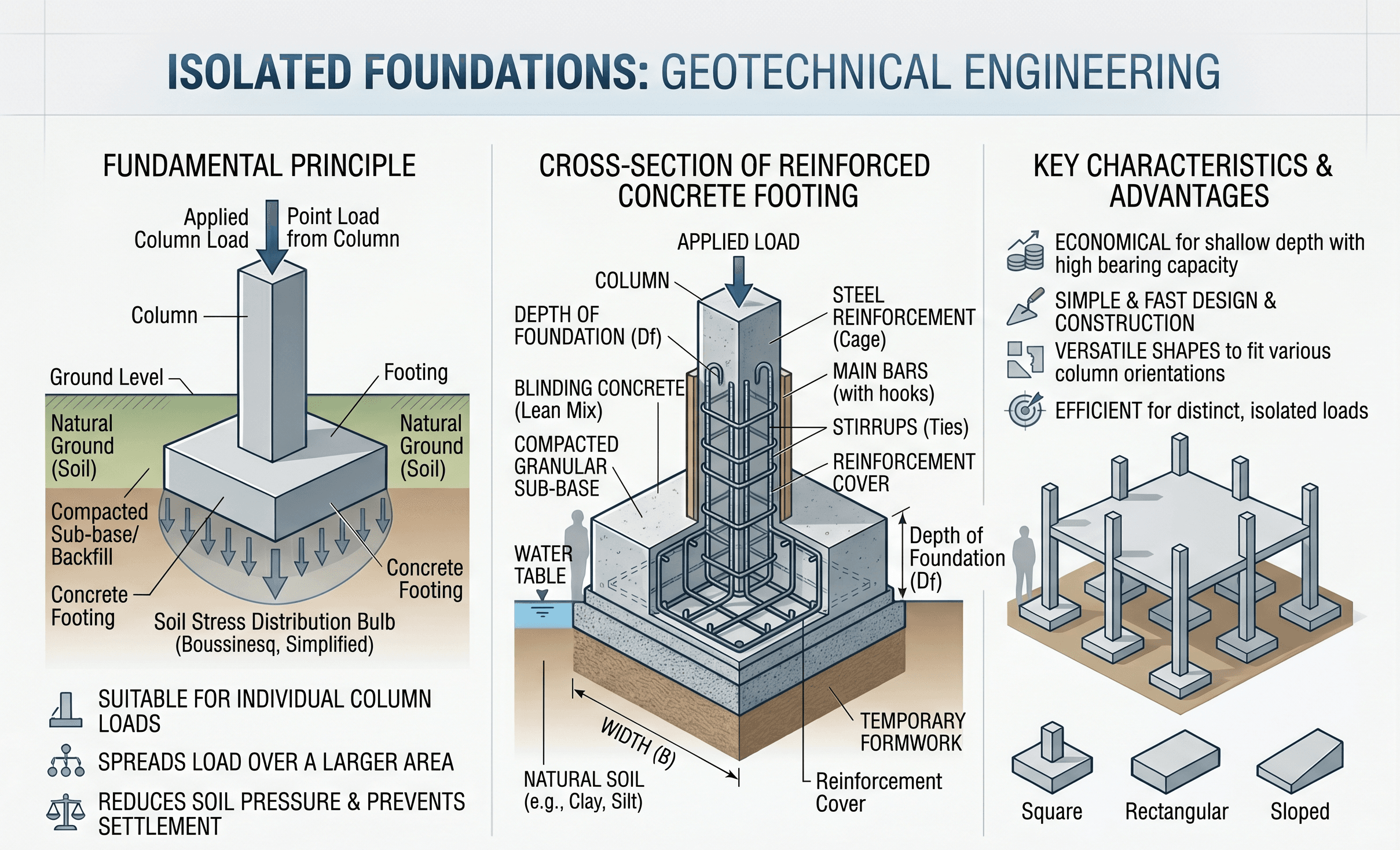
Notice the relationship between column load, footing width, embedment depth, and the supporting soil layer. The best isolated foundation designs treat bearing, settlement, and constructability as one system rather than separate checks.
What are isolated foundations?
An isolated foundation is a shallow foundation unit placed under a single column, pier, post, or other concentrated support point. Its purpose is straightforward: take a relatively high structural reaction and distribute it over enough soil area that the supporting ground can resist the load safely and with acceptable settlement.
Engineers also refer to these as isolated footings, spread footings, or, on many projects, pad foundations. The exact naming can vary by office, region, or structural discipline, but the core concept is the same: a discrete foundation element serving one concentrated reaction rather than a continuous wall load or a group of closely spaced columns.
Isolated foundations are attractive because they are often economical, easy to understand, and efficient to build when the site has competent near-surface soils and the column grid is reasonably spaced. They also work well when excavation can stay localized and when differential movement between adjacent supports is expected to remain modest.
The mistake is thinking they are selected only by dividing load by allowable bearing pressure. That is only the start. A footing can satisfy a simple average stress calculation and still perform poorly if the soil is variable, settlement is excessive, groundwater softens the base, or eccentric loading causes uneven contact pressure.
Core principles, variables, and units
Isolated foundation behavior sits at the intersection of geotechnical and structural design. Geotechnically, the footing must keep soil pressures and settlement within acceptable limits. Structurally, the concrete footing must resist flexure, one-way shear, and punching shear around the column.
What usually controls the design
On small projects, bearing pressure may govern the first sizing pass. On real projects, settlement often becomes the more important serviceability check, especially in soft clays, loose fills, variable natural deposits, or sites where adjacent columns carry very different loads. Construction depth, frost protection, groundwater, edge distance near property lines, and column eccentricity can also become the controlling issue.
Key variables and typical ranges
The most useful footing variables are not just symbols on a page. They represent the handful of things that most directly change the size, thickness, and viability of a footing. A good designer develops intuition for whether a number “looks right” before trusting a software output.
- P Service or factored column load; commonly kN or kips. This is the starting demand that the footing must transfer into soil.
- A Footing contact area, usually m² or ft². Larger area reduces average soil pressure but increases concrete volume and excavation.
- q Contact pressure at the soil-footing interface, typically kPa, psf, or ksf. Average pressure is not enough when moments or eccentricity exist.
- qall Allowable bearing pressure or allowable net pressure from the geotechnical basis. This is often tied to both strength and settlement criteria.
- B, L Footing plan dimensions. These control pressure distribution, structural span within the footing, and construction footprint.
- Df Embedment depth, usually measured from grade to foundation base. Depth is affected by frost, erosion, surface disturbance, and the target founding stratum.
- s Settlement, often broken into total and differential settlement. Small settlements can still be damaging when adjacent supports move unequally.
- e Load eccentricity. When the column load is offset from footing centroid, contact pressure becomes nonuniform and uplift may develop at one edge.
Do not treat an allowable bearing value as a universal material property of the site. It is a project-specific recommendation tied to footing size, depth, groundwater, soil variability, and acceptable movement.
Decision logic or design workflow
The fastest way to understand isolated foundations is to follow the sequence an engineer actually uses. The workflow is less about one perfect equation and more about narrowing uncertainty until a discrete footing becomes a defensible solution.
Start with site characterization and geotechnical recommendations. Confirm whether near-surface soil is competent enough for shallow support. Check column spacing and load magnitudes. Make a first-pass footing area from allowable pressure. Then verify settlement, eccentricity, sliding or overturning if lateral demand matters, and structural concrete checks. If the footing becomes too large, too thick, too eccentric, or too sensitive to soil variability, move to a combined, strip, raft, or deep foundation alternative.
This design path matters because isolated foundations are usually chosen for economy. Once separate footings begin overlapping, crowding each other, or forcing large tie beams and grade beams to manage eccentricity, the “simple” solution often stops being the best solution.
Equations and calculations
A first-pass isolated footing size usually starts with average bearing pressure. This is not the full design, but it is a useful screening equation that tells you whether a discrete footing is even in the right range.
Here, \(P\) is the applied load at the footing base and \(A = BL\) is the footing contact area. In early sizing, the designer selects \(B\) and \(L\) so that the resulting average pressure stays below the allowable or recommended contact pressure for the site.
When the column load includes moment or is offset from the footing centroid, pressure is no longer uniform. For a footing under axial load and bending, the contact stress shifts, and one side may carry a much higher pressure than the average value suggests.
This simplified form communicates the key idea: eccentricity increases pressure on one side and reduces it on the other. If eccentricity becomes too large, part of the footing may lose contact, which changes the effective bearing area and can invalidate simple assumptions.
In geotechnical terms, settlement checks are just as important. Even if \(q_{avg}\) is below a recommended allowable value, isolated foundations may still perform poorly if compressible layers extend below the footing influence zone. That is why geotechnical reports often tie allowable pressures to both bearing capacity and movement criteria rather than strength alone.
Worked example
Example
Consider a building column with a service reaction of 900 kN supported on medium-dense sand. Suppose the geotechnical recommendations allow a net service contact pressure of 180 kPa for footings in the expected size range. A first-pass required area is:
A square footing would therefore start near \( \sqrt{5.0} \approx 2.24\ \text{m} \), so the designer may round to a practical 2.3 m by 2.3 m footing and continue with structural and serviceability checks. The average contact pressure becomes:
That looks acceptable on a first pass, but the design is not done. The team still needs to check footing thickness, reinforcement, punching shear around the column, one-way shear, dowel or pedestal detailing, base elevation, groundwater effects during excavation, and whether settlements remain acceptable relative to adjacent columns with different loads.
Now imagine the actual site includes a thin loose fill layer over the sand, with some variability across the building footprint. Even though the average stress math still works, field preparation becomes critical. Unsuitable material may need removal and replacement, and the engineer may require proof that the footing bears on competent undisturbed material rather than a disturbed or softened base.
Engineering judgment and field reality
Real isolated foundation performance depends heavily on how the footing base is exposed, protected, and inspected. A footing designed on clean assumptions can lose capacity margin quickly if the excavation base is overdug, softened by water, left exposed too long, or partly founded on uncontrolled fill.
This is why experienced engineers care so much about founding stratum confirmation. The plan dimensions may look perfect on paper, but if one footing bears on dense natural sand and the next bears partly on loose backfill, differential settlement can become the real project problem.
Another field reality is geometry. Property lines, existing utilities, adjacent basements, and nearby footings often force offset columns or irregular plan dimensions. That introduces eccentricity, which can make the discrete isolated footing less attractive than the original concept suggested.
The most reliable isolated footing details are paired with simple construction rules: found on verified competent material, protect the base from water and disturbance, remove unsuitable pockets immediately, and stop work when actual soil conditions differ materially from the assumed profile.
When this breaks down
Isolated foundations stop being the obvious answer when one or more of their core assumptions fail. The first breakdown case is weak or highly compressible near-surface soil. If footing area must become very large just to control stress or settlement, the excavation and concrete quantity can make a raft or deep foundation system more rational.
A second breakdown case is close column spacing. When individual footings nearly overlap, the job may be telling you that separate supports are no longer the cleanest system. Combined foundations, strip foundations, or a mat can produce a better load path and easier construction.
Large moments or offset property-line conditions are another trigger. Once eccentricity becomes significant, contact pressure can become highly nonuniform. You may need strap beams, tie beams, or geometry changes that erase the simplicity that made isolated foundations attractive in the first place.
They also break down in variable fills, expansive soils, collapsible soils, liquefaction-prone ground, or sites where groundwater or seasonal moisture swings can materially change the support conditions. In those cases, the design question is not just footing size. It is whether shallow isolated support is the right concept at all.
Common pitfalls and engineering checks
- Using one allowable bearing value everywhere without checking whether footing size, depth, or soil variability changes the recommendation.
- Focusing only on ultimate strength and underestimating serviceability settlement or differential settlement risk.
- Ignoring eccentricity from property-line offsets, lateral load effects, or pedestal geometry.
- Assuming the excavation base will match the boring log exactly without field verification.
- Forgetting that structural footing thickness and shear checks can enlarge the footing depth even when geotechnical sizing looks modest.
One of the costliest mistakes is treating isolated footing sizing as a single bearing-capacity exercise. On many jobs, settlement compatibility and field conditions drive performance more than ultimate capacity does.
| Parameter | Symbol | Typical units | Notes |
|---|---|---|---|
| Column reaction | P | kN, kips | May be service load, factored load, or a combination depending on the check being performed. |
| Average contact pressure | q | kPa, psf, ksf | Average pressure is only a screening value when moment or eccentricity exists. |
| Allowable pressure | qall | kPa, psf, ksf | Usually tied to geotechnical recommendations and project-specific movement tolerance. |
| Embedment depth | Df | m, ft | Affected by frost depth, erosion, site grading, and the desired founding layer. |
| Settlement | s | mm, in | Total and differential movement should both be considered. |
Visualizing isolated foundations in the design process
A useful mental sketch is to picture isolated foundations as the “single-node” version of shallow support. Strip foundations serve line loads, combined foundations serve two or more closely spaced columns, and raft foundations spread many reactions together. Isolated foundations sit at the simplest end of that progression.
That comparison helps during concept design. If the grid is regular, soils are competent, and column loads are reasonably separated, isolated footings often remain the most buildable option. If those conditions start to weaken, the designer should stop optimizing the discrete footing and start questioning the system choice itself.
This section stays text-only because the primary infographic already carries the main instructional visual load for the page.
Relevant standards and design references
Isolated foundation design is usually built from both code requirements and project-specific geotechnical recommendations. The standards below are especially useful because they connect structural checks, subsurface interpretation, and construction verification.
- IBC / local building code: Establishes the governing code framework for foundation support, soil-bearing references, frost protection, and related structural compliance items.
- ACI 318: Commonly used for reinforced concrete footing design, including flexure, one-way shear, punching shear, development, and detailing.
- Geotechnical report for the project: Often the most directly useful footing reference because it translates subsurface conditions into recommended founding depths, allowable pressures, and construction requirements.
- ASTM soil and field testing standards: Support the classification, sampling, and laboratory basis behind the soil parameters used for footing recommendations.
- Agency or owner criteria: Some sectors, campuses, utilities, and industrial owners impose stricter movement tolerances or foundation QA requirements than minimum code alone.
Frequently asked questions
In most building and geotechnical contexts, they mean essentially the same thing: a discrete shallow footing supporting one column or concentrated load. “Pad foundation” is often the more informal term, while “isolated foundation” helps distinguish the system from strip, combined, or raft foundations.
The controlling issue is often a combination of bearing pressure, settlement, footing shear and bending, eccentricity, groundwater, frost depth, and the actual founding material exposed during construction. On many jobs, movement and constructability matter as much as pure bearing strength.
They become less attractive when soil is weak or highly compressible, column spacing is tight, property-line eccentricity is large, or the footing must grow so much that a combined, strip, raft, or deep system becomes cleaner and more economical.
They are common beneath steel and concrete building columns, light industrial frames, equipment supports, canopies, sign structures, and other layouts where loads are concentrated and can be supported independently without continuous footing geometry.
Summary and next steps
Isolated foundations are one of the most common shallow foundation solutions because they are simple, efficient, and often economical when the site has competent near-surface support and the structural layout provides reasonably separated column loads. Their role is to spread concentrated reactions into the ground without triggering unacceptable bearing stress or settlement.
The main practical lesson is that isolated footings are never just an area calculation. Good decisions come from combining geotechnical recommendations, structural footing checks, field confirmation of the founding material, and honest judgment about whether a separate footing system still makes sense as conditions become more constrained.
If you remember one thing, remember this: when isolated foundations start requiring oversized plan dimensions, unusual eccentric details, or heavy dependence on idealized soil assumptions, the project may be signaling that another foundation type deserves serious consideration.
Where to go next
Continue your learning path with these curated next steps.
-
Read a deeper dive on foundation design
This is the natural next step if you want to compare isolated foundations with other shallow and deep support systems.
-
Study the most closely related comparison topic
Use this when separate footings are getting too close together or eccentricity is starting to drive the layout.
-
Practice with a related Turn2Engineering calculator
Apply the geometry and takeoff side of footing work with a calculator built around strip and isolated footing configurations.