Key Takeaways
- Core idea: A relay uses one electrical signal to switch, isolate, interlock, alarm, or command another circuit.
- Engineering use: Relays are used in control panels, motor circuits, PLC interfaces, alarms, breaker trip circuits, and power system protection schemes.
- What controls it: Relay selection depends on input voltage, contact type, contact rating, load behavior, timing, isolation, duty cycle, and failure consequence.
- Practical check: In power systems, a protective relay usually detects and commands; the circuit breaker, recloser, or fuse performs the current interruption.
Table of Contents
Introduction
Relays are electrically controlled devices that use one signal to switch, isolate, interlock, or command another circuit. A basic relay uses a coil and contacts to turn a load on or off, while a power system protective relay monitors current, voltage, frequency, impedance, or phase angle and sends trip or alarm commands when equipment is in danger.
How a Basic Relay Works
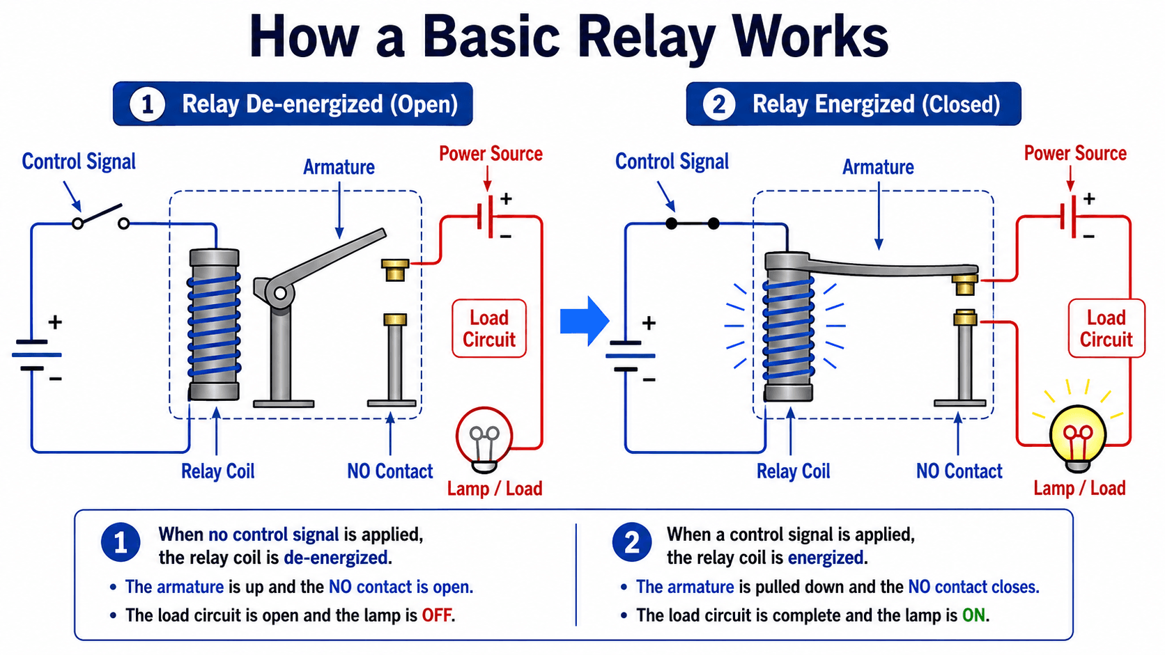
Notice the two different circuits: the blue control circuit operates the relay coil, while the red load circuit carries power to the lamp or equipment. That separation is one of the main reasons relays are useful in electrical control.
What Is a Relay?
A relay is a device that changes an output state in response to an input signal. In a traditional electromechanical relay, an energized coil creates a magnetic field that moves an armature and changes contact position. In a solid-state relay, a semiconductor output performs the switching without moving contacts. In a protective relay, measurement inputs and logic determine whether an alarm, lockout, or breaker trip should occur.
The practical value of a relay is control separation. A relay lets a low-power signal influence a different circuit that may have a different voltage, grounding reference, current level, or safety function. In a control panel, that may mean using a 24 VDC control signal to switch a 120 VAC pilot light. In a substation, it may mean using CT and PT inputs to determine whether a circuit breaker should open.
A relay is not automatically a breaker, fuse, contactor, overload device, or arc-rated interrupting device. Some equipment combines relay logic and interruption in one package, but the relay function itself is sensing, switching, isolation, logic, or control.
Relay Components and Contact Logic
Relay behavior is easiest to understand by separating the input side from the output side. The input side receives the control signal, sensing signal, or measurement input. The output side changes state by opening a contact, closing a contact, energizing an output, or sending a digital command.
| Relay term | What it means | Why it matters in design |
|---|---|---|
| Coil or input | The electrical input that causes the relay to operate. | The coil or input voltage must match the control system, such as 24 VDC, 120 VAC, or a digital relay input. |
| Armature | The moving mechanical element in an electromechanical relay. | Its movement creates contact changeover, but it also introduces mechanical wear and operating time. |
| Normally open contact | A contact that is open when the relay is not energized. | Used when a load, alarm, or command should turn on only after relay operation. |
| Normally closed contact | A contact that is closed when the relay is not energized. | Used for permissive circuits, fail-safe logic, interlocks, and loss-of-power indication. |
| Common terminal | The shared terminal in a changeover contact arrangement. | Helps determine which circuit path is connected before and after relay operation. |
| Contact rating | The voltage, current, and load type the contact can safely switch. | Ratings must account for AC or DC switching, inductive loads, inrush current, and expected duty cycle. |
How to Read a Simple Relay Circuit
Start by identifying the coil or input terminals. Then identify the contacts and determine whether each contact is normally open or normally closed in the de-energized state. Follow the load circuit path through the contact and ask what changes when the relay energizes. Finally, verify that the contact rating is suitable for the load, not just that the schematic shows a contact.
Normally Open vs Normally Closed
“Normally” describes the relay’s de-energized state. A normally open contact closes when the relay operates. A normally closed contact opens when the relay operates. That difference is critical in shutdown logic, alarms, permissive circuits, and protection schemes where the safer state may depend on whether control power is present.
Contact Logic Is Not the Same as Load Capability
A contact arrangement tells you how the relay switches, but it does not prove the relay can safely switch the load. A small interposing relay may be fine for a PLC input or indicating lamp but unsuitable for a motor load, DC inductive circuit, or breaker trip circuit unless the contact rating and application are appropriate.
Relay Contact Types, Symbols, and Terminal Logic
Relay diagrams use contact symbols to show what is connected before and after relay operation. The contact arrangement tells you how many independent circuits can be switched and whether the relay connects, disconnects, or changes over between two paths.
| Contact arrangement | Meaning | Typical use |
|---|---|---|
| SPST | Single pole, single throw; one circuit path is opened or closed. | Simple on/off control for a pilot light, small load, alarm, or permissive signal. |
| SPDT | Single pole, double throw; one common terminal changes between NO and NC paths. | Status changeover, alarm logic, control selection, or fail-safe indication. |
| DPDT | Double pole, double throw; two independent circuits change state together. | Switching two isolated circuits from the same relay operation. |
| Form A | Normally open contact. | Closes when the relay operates. |
| Form B | Normally closed contact. | Opens when the relay operates. |
| Form C | Changeover contact with common, NO, and NC terminals. | Transfers a circuit from one path to another when the relay operates. |
When reviewing a relay schematic, always read contacts in their normal, de-energized state unless the drawing explicitly says otherwise. Then mentally energize the relay and confirm which contacts close, which contacts open, and what load or logic path changes.
Where Relays Are Used
Relays appear anywhere electrical control needs isolation, logic, sequencing, monitoring, or protection. The same basic concept applies across small control panels and large power systems, but the relay’s ratings, sensing method, and failure consequences change dramatically.
- Motor starter control: Relays can energize contactor coils, provide interlocks, and coordinate start/stop logic.
- Pump and process panels: Relays can respond to float switches, pressure switches, alarms, and permissive contacts.
- PLC interposing circuits: Interposing relays isolate PLC outputs from field devices or provide additional contacts.
- Alarm and annunciator circuits: Relays can convert a field condition into an alarm, light, horn, or remote status input.
- Breaker trip and close circuits: Auxiliary and protective relays can supervise or command breaker operation.
- Power system protection: Protective relays monitor feeders, transformers, generators, motors, buses, and transmission lines.
For power system fault studies that support relay application and coordination, see the Turn2Engineering guide to short circuit analysis.
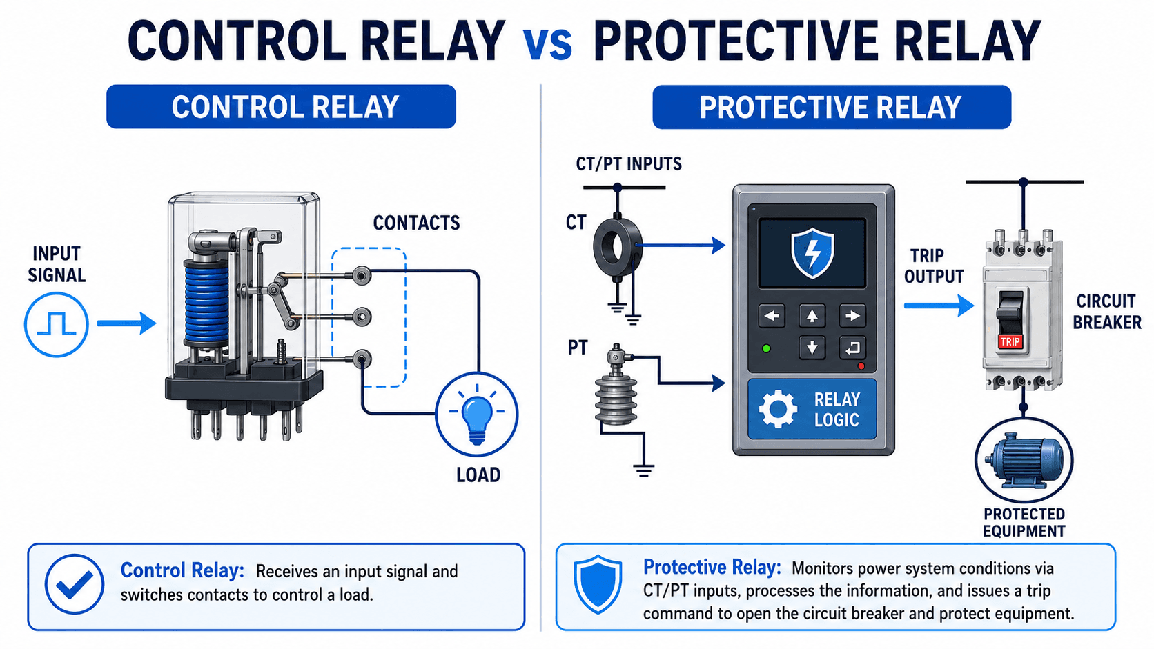
Control Relays vs Protective Relays
A control relay usually switches control circuits, interlocks, indicators, auxiliary contacts, or contactor coils. A protective relay monitors electrical conditions and decides whether a piece of equipment, feeder, line, transformer, motor, generator, or bus should remain energized.
| Relay category | Main job | Typical inputs | Typical outputs |
|---|---|---|---|
| Control relay | Switches a control or auxiliary circuit. | Pushbutton, PLC output, limit switch, control voltage, or permissive signal. | Contact closure, pilot light, interlock, contactor coil, or alarm circuit. |
| Interposing relay | Provides isolation or extra contacts between systems. | PLC output, automation output, or one control voltage. | Contacts that switch a different voltage, isolate field wiring, or multiply outputs. |
| Auxiliary relay | Multiplies contacts, isolates circuits, or expands control logic. | Control signal from another relay, switch, or automation system. | Multiple NO/NC contacts for interlocks, status signals, or trip circuit logic. |
| Protective relay | Detects abnormal electrical conditions and initiates protection action. | CTs, PTs/VTs, frequency, voltage, current, impedance, digital status, or communication logic. | Trip command, alarm, lockout, reclosing command, blocking signal, or event record. |
Common Types of Relays
Relay type is selected from the job the relay must perform. The same word can describe a small plug-in control relay, a solid-state switching device, a thermal overload relay, a lockout relay, or a microprocessor protective relay in a substation panel.
| Relay type | Where it is used | Engineering notes |
|---|---|---|
| Electromechanical relay | Control panels, interlocks, auxiliary circuits, and simple switching logic. | Provides visible contact action and isolation, but contacts wear and coils can fail. |
| Solid-state relay | Fast or frequent switching where no moving contacts are desired. | Has no mechanical contact wear, but leakage current, heat dissipation, voltage drop, and failure behavior must be reviewed. |
| Reed relay | Low-current signal switching, instrumentation, and fast small-signal control. | Useful for small signals, but not appropriate for high-energy load switching. |
| Time-delay relay | Sequencing, motor controls, transfer schemes, alarms, and process delays. | Useful when a circuit should operate only after a defined delay or remain energized for a set time. |
| Latching relay | Circuits that must hold state after a pulse or loss of input signal. | Good for memory-like control behavior, but reset logic must be clear. |
| Thermal overload relay | Motor overload protection and equipment thermal protection. | Responds to overload behavior and heating, not necessarily high-speed short-circuit protection. |
| Lockout relay | Protection and control schemes where a trip should require deliberate reset. | Often used to prevent automatic re-energization after serious faults or protection operations. |
| Protective relay | Power systems, switchgear, substations, feeders, transformers, generators, motors, buses, and lines. | Requires settings, CT/PT inputs, trip circuit review, coordination, testing, and event analysis. |
Electromechanical Relays vs Solid-State Relays
The most common relay comparison is electromechanical relay versus solid-state relay. Both can switch a circuit, but they behave differently during operation, failure, heat buildup, off-state conditions, and frequent switching.
| Comparison | Electromechanical relay | Solid-state relay |
|---|---|---|
| Switching method | Uses a coil, magnetic movement, armature, and physical contacts. | Uses semiconductor devices such as triacs, thyristors, MOSFETs, or optically isolated inputs. |
| Contact wear | Contacts can pit, arc, oxidize, weld, or wear with switching duty. | No mechanical contact wear, but semiconductor stress and heat still matter. |
| Off-state behavior | Open contacts generally provide a true physical air gap. | May have off-state leakage current that can affect sensitive loads. |
| Switching speed | Limited by mechanical movement and contact bounce. | Usually faster and better for frequent switching. |
| Heat | Coil heating may matter, but load-side conduction heat is often lower. | Output voltage drop and load current can require heat sinking. |
| Failure behavior | Can fail open, fail to pick up, chatter, or weld contacts closed. | Can fail shorted, leak current, overheat, or be damaged by transients. |
| Best fit | General control, visible isolation, auxiliary contacts, and mixed control schemes. | Fast, quiet, frequent switching where leakage and heat are acceptable. |
Solid-state relays are not automatically better than electromechanical relays. SSRs remove moving contacts, but they introduce leakage current, heat management, transient sensitivity, and device-specific AC/DC output limitations.
Relay Ratings That Matter
A relay symbol on a drawing does not prove the device is correctly rated. Relay ratings must be checked against the actual control source, load type, switching duty, and failure consequence.
| Rating or condition | What to check | Why it matters |
|---|---|---|
| Coil or input voltage | Nominal voltage, AC/DC type, pickup voltage, dropout voltage, and tolerance. | Wrong input voltage can cause chatter, overheating, nuisance dropout, or failure to operate. |
| Contact voltage | Maximum voltage the contact can safely open and close. | DC arcs are harder to interrupt than AC arcs, so AC and DC ratings are not interchangeable. |
| Contact current | Continuous current, switching current, inrush current, and overload duty. | A contact may carry current after closing but still be unable to safely make or break that current repeatedly. |
| Load type | Resistive, inductive, capacitive, motor, lamp, solenoid, or electronic load. | Inductive loads produce voltage spikes, lamps can have high inrush, and capacitive loads can stress contacts at closing. |
| Mechanical and electrical life | Expected number of operations with and without load switching. | Mechanical life may look high, but electrical life can be much lower under real switching duty. |
| Isolation rating | Separation between input and output circuits and between contact circuits. | Isolation protects controls, operators, and equipment when circuits use different voltages or grounding references. |
| Temperature and enclosure | Ambient temperature, panel heating, ventilation, dust, moisture, and vibration. | Relays in outdoor panels, switchgear, and industrial cabinets may operate far from ideal room-temperature conditions. |
How Relays Are Used in Power Systems
In power systems, relays are often part of a protection and control chain. Current transformers and voltage transformers reduce primary system quantities to measurable values. The relay evaluates those inputs against settings and logic. If the measured condition indicates a fault or unsafe operating state, the relay issues a trip command to the breaker trip circuit.
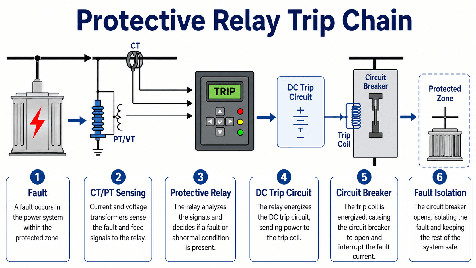
The Protective Relay Trip Chain
A typical trip sequence begins with a fault inside a protected zone. CTs and PTs/VTs feed scaled measurements to the relay. The relay compares those measurements to settings, timing curves, directional logic, differential logic, or other protection functions. When the trip condition is satisfied, the relay closes an output contact or sends a command that energizes the breaker trip coil.
Protection Goals: Selectivity, Speed, Sensitivity, Security, and Dependability
Protective relay schemes must balance several goals. Selectivity means tripping only the intended zone. Speed limits equipment damage and system disturbance. Sensitivity allows the relay to detect the lowest relevant abnormal condition. Security means avoiding unwanted trips. Dependability means tripping when a valid fault occurs. Coordination ties those goals together across upstream and downstream devices.
Primary and Backup Protection
A well-designed protection system does not depend on one relay alone. Primary protection should clear faults in its assigned zone, while backup protection should operate if the primary relay, breaker, control power, wiring, or communication-assisted scheme fails. That is why relay coordination is reviewed as a system rather than as isolated device settings.
Common Protective Relay Functions
Protective relays are often described by device numbers or function names. These functions do not always exist as separate physical relays anymore; modern digital relays may include many functions in one device. The engineering task is to choose, set, test, and coordinate the functions that fit the protected equipment.
| Function | What it detects | Typical power system use |
|---|---|---|
| 50 instantaneous overcurrent | High current above an instantaneous pickup level. | Fast tripping for high-magnitude faults when coordination allows. |
| 51 time overcurrent | Current above pickup for a time determined by a curve. | Feeder, transformer, motor, and backup protection where time coordination matters. |
| 67 directional overcurrent | Overcurrent in a specific direction. | Looped networks, parallel feeders, distributed generation, and systems where fault direction matters. |
| 87 differential | Mismatch between current entering and leaving a protected zone. | Fast selective protection for transformers, buses, generators, motors, and some lines. |
| 21 distance | Apparent impedance between the relay location and a fault. | Transmission line protection with zones of reach and backup coverage. |
| 27/59 voltage | Undervoltage or overvoltage conditions. | Equipment protection, load shedding, generator protection, and voltage abnormality alarms. |
| 81 frequency | Underfrequency, overfrequency, or frequency rate conditions. | Generator protection, grid stability schemes, and load-shedding logic. |
| 25 synch-check | Voltage, angle, and frequency conditions before closing. | Breaker closing supervision between energized sources or buses. |
| 79 reclosing | Automatic reclosing logic after a trip. | Overhead line protection where many faults are temporary and reclosing may restore service. |
For a deeper look at one of the most selective relay methods, see the Turn2Engineering guide to differential protection.
Relay Selection and Review Checklist
A relay should be selected around the circuit it controls and the consequence of wrong operation. The checklist below is useful for control relay applications, monitoring relays, interposing relays, and early protective relay review.
Define the relay’s job first: switch a load, isolate a control circuit, provide an interlock, monitor a condition, or command protection action. Then verify the input source, output duty, failure mode, timing, environment, and testing requirements before choosing the device.
| Relay review item | What to look for | Why it matters |
|---|---|---|
| Control voltage or input type | AC or DC input, nominal voltage, tolerance, pickup voltage, dropout voltage, and available control power. | A mismatched coil or input can chatter, fail to operate, overheat, or remain picked up when it should drop out. |
| Contact or output rating | Voltage, current, AC/DC rating, inductive load rating, inrush current, and expected switching frequency. | Contacts that look acceptable for steady current may fail when switching DC, coils, lamps, motors, or high-inrush loads. |
| NO/NC logic and fail-safe behavior | What the circuit does when the relay is de-energized, energized, loses power, or has a failed contact. | Shutdown, trip, permissive, and alarm circuits often require intentional de-energized-state logic. |
| Isolation requirement | Whether control and load circuits need galvanic isolation, different grounds, or different voltage classes. | Isolation is often the reason a relay is used instead of a direct semiconductor output or PLC output. |
| Timing requirement | Pickup time, dropout time, intentional delay, reset time, and coordination with other devices. | Milliseconds can matter in protection and automation, while nuisance delay can affect process control or interlocks. |
| Environment and duty | Temperature, vibration, dust, moisture, enclosure rating, coil heating, and operations per day. | Relays in panels, substations, vehicles, and industrial sites experience different mechanical and thermal stresses. |
| Testing and maintainability | Test switches, terminal access, indicating targets, event records, spare contacts, and replacement availability. | A relay that cannot be tested or isolated safely becomes a maintenance and troubleshooting problem. |
Relay vs Breaker vs Contactor vs Fuse
Relays are often confused with other switching and protection devices because they are used in the same panels and schemes. The difference is not just size; it is the device’s primary job.
| Device | Primary job | Where relays fit |
|---|---|---|
| Relay | Senses, controls, switches a control circuit, or issues an output command. | May command another device, provide interlocking, or switch smaller loads directly if rated. |
| Circuit breaker | Opens a power circuit and interrupts current within its rating. | A protective relay may tell the breaker when to trip. |
| Contactor | Frequently switches power loads such as motors, heaters, lighting banks, or capacitor banks. | A relay may energize the contactor coil or supervise contactor control logic. |
| Fuse | Melts under overcurrent to interrupt the circuit once. | Relays may coordinate with fuses or provide additional monitoring, but the fuse performs the interruption. |
| Recloser | Interrupts distribution faults and automatically recloses according to programmed logic. | Modern reclosers often integrate sensing, relay logic, interruption, and reclosing in one package. |
For more context on protective devices that coordinate with relays, see the Turn2Engineering pages on overcurrent protection and switchgear.
Engineering Judgment and Field Reality
Relay drawings are clean, but real circuits include terminal blocks, auxiliary contacts, lockout relays, test switches, DC control power, fuses, trip coils, communication links, and maintenance bypass procedures. A relay output that looks correct on a schematic can still fail in service if the control power is weak, a contact is underrated, a CT circuit is miswired, or a breaker trip coil is not healthy.
In protection work, relay settings are only part of the system. Engineers also review CT ratios, PT ratios, polarity, wiring, breaker trip circuits, DC station battery condition, test switch positions, event records, and coordination with upstream and downstream protection.
This is why relay work is often reviewed with the broader protection scheme. A relay may operate exactly as set and still produce an undesirable outage if the setting logic, time coordination, or protected-zone boundary is wrong.
When This Breaks Down
Simplified relay explanations break down when the relay is treated as a perfect switch or a stand-alone protection solution. Real relays have ratings, operating delays, contact limitations, sensing errors, settings, and failure modes.
- Underrated contacts: Contacts may weld, pit, or fail open when switching inductive loads, DC circuits, high inrush currents, or trip coils beyond their rating.
- Control power problems: A relay may chatter, fail to pick up, or fail to trip a breaker if the AC control circuit or DC station battery cannot support the operation.
- Incorrect CT/PT inputs: Polarity errors, ratio errors, open CT circuits, blown PT fuses, or saturated CTs can cause incorrect relay decisions.
- Settings without coordination: A relay set too fast or too sensitive can trip upstream equipment unnecessarily; one set too slow may fail to protect equipment adequately.
- Solid-state relay assumptions: SSRs can leak current when “off,” generate heat, and fail differently than electromechanical contacts.
Common Relay Mistakes and Practical Checks
Most relay mistakes come from assuming the symbol tells the whole story. The schematic may show a contact, but it does not automatically show the contact duty, source of control power, trip circuit health, or failure response.
| Common mistake | Practical check | Why it matters |
|---|---|---|
| Using a relay contact for a load it is not rated to switch. | Check AC/DC contact rating, inductive rating, inrush current, and expected operations. | Contact failure can create nuisance outages, failed starts, welded circuits, or unsafe control behavior. |
| Assuming the relay interrupts the fault current. | Identify the actual interrupting device: breaker, fuse, recloser, or switchgear assembly. | Protection design depends on interrupting rating, clearing time, and coordination, not just relay logic. |
| Ignoring de-energized-state logic. | Confirm what happens when control power is lost or the relay drops out. | Fail-safe circuits often depend on normally closed contacts and loss-of-power behavior. |
| Mixing up control relay logic and protective relay functions. | Separate auxiliary switching tasks from measurement-based protection tasks. | A plug-in control relay cannot replace a properly applied protective relay scheme. |
| Testing only the relay faceplate or output indication. | Verify the full path from sensing input through output contact, trip circuit, trip coil, and breaker operation. | A relay target or trip LED does not prove the breaker actually opened or the protected zone was isolated. |
Do not size a relay only by the normal running current of the load. Switching stress, inrush, inductive kick, DC arc behavior, duty cycle, and failure consequences can be more important than steady-state current.
Useful References and Design Context
Relay application in power systems is supported by standards, manufacturer manuals, utility practices, protection studies, commissioning procedures, and site-specific criteria. A general resource page can explain the concepts, but actual protective relay settings and test procedures must be developed around the equipment, fault study, coordination study, and owner requirements.
- IEEE power system relays standards collection: review the IEEE power system relays standards overview to see the range of standards and guides associated with protective, regulating, monitoring, reclosing, synch-check, synchronizing, and auxiliary relays.
- Project-specific criteria: Relay application may also be controlled by utility standards, equipment manuals, arc-flash studies, short-circuit studies, coordination studies, commissioning plans, and owner operating practices.
- Engineering use: Engineers use these references to select relay functions, define protected zones, coordinate trip timing, verify testing requirements, and document how relay action supports system reliability.
Frequently Asked Questions
A relay is an electrically controlled switching or decision device. A basic relay uses a control signal to open or close contacts, while a protective relay monitors power system conditions and sends alarm or trip commands when abnormal conditions are detected.
A relay senses, controls, or makes a decision, while a circuit breaker physically opens the power circuit and interrupts current. In many power systems, the relay detects the fault and sends a trip signal, while the breaker performs the actual interruption.
A control relay usually switches auxiliary circuits, interlocks, indicators, contactor coils, or small loads. A protective relay monitors power system quantities such as current, voltage, frequency, impedance, or phase angle and commands alarms or breaker trips when equipment or system conditions become abnormal.
Most protective relays do not interrupt fault current by themselves. They make the protection decision and energize a trip circuit, while a circuit breaker, recloser, fuse, or other interrupting device opens the power circuit.
Relays can fail from coil burnout, contact wear, welded contacts, loose wiring, heat, contamination, incorrect voltage, excessive switching duty, poor trip circuit health, or solid-state leakage and shorted-output failures.
Summary and Next Steps
Relays are the link between electrical sensing, control logic, and switching action. A simple relay may use a coil and contacts to control a load, while a protective relay may process CT and PT inputs and command a circuit breaker trip when it detects a fault or abnormal condition.
The practical engineering work is not just knowing the relay symbol. Relay application requires checking input voltage, contact duty, load behavior, failure mode, protected-zone boundaries, timing, coordination, control power, and testing access.
Where to go next
Continue your learning path with related Turn2Engineering resources.
-
Protective Relays
Learn how protective relays detect abnormal power system conditions and initiate alarms, trips, reclosing, or backup protection.
-
Transmission Line Protection
See how relay zones, distance protection, pilot schemes, and backup logic are applied to high-voltage lines.
-
Short Circuit Analysis
Review the fault-current studies that support relay settings, equipment duties, and protection coordination.