
Table of Contents
Introduction
A variable air volume system, or VAV system, is a commercial HVAC system that changes the airflow delivered to each building zone as its load changes. A central air handling unit supplies conditioned air, while VAV terminal boxes, zone sensors, duct-pressure controls, and a variable-speed fan coordinate airflow throughout the building.
A VAV box is only one part of the system. The complete VAV system also includes the air handling unit, supply ductwork, pressure sensor, variable-frequency drive, zone controls, diffusers, return-air path, and building automation system.
Key Takeaways
- What varies: The quantity of supply air delivered to each zone changes as the zone load changes.
- What controls it: Zone temperature, airflow measurement, damper position, duct static pressure, and supply-fan speed work together.
- Why it is used: VAV systems provide individual zone control and can reduce unnecessary fan airflow during part-load operation.
- What commonly goes wrong: Sensor errors, incorrect airflow limits, low duct pressure, stuck dampers, reheat conflicts, and incomplete commissioning can all create comfort problems.
How a VAV System Works
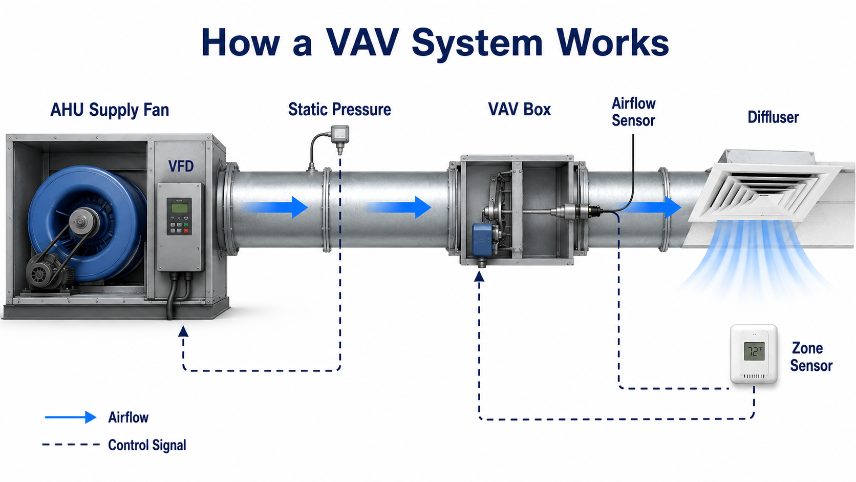
A VAV system uses two connected control loops. The first regulates airflow at each zone. The second adjusts the central supply fan as terminal dampers throughout the building open and close.
1. Zone temperature creates an airflow command
The zone sensor compares room temperature with the active setpoint. When a zone requires more cooling, the terminal controller increases its airflow command. When the cooling load falls, the controller reduces the airflow command toward the programmed minimum.
2. The VAV box regulates zone airflow
In a pressure-independent terminal, an airflow sensor measures the air entering the box. The controller compares measured airflow with commanded airflow and moves the damper until the two values agree within the terminal’s operating range.
The airflow command is normally limited between a programmed minimum and maximum. These limits should be based on zone load, ventilation, diffuser performance, acoustics, terminal capability, and the approved control sequence—not copied blindly from another zone.
3. Terminal movement changes duct pressure
When many terminal dampers open, the duct system experiences less resistance and requires more fan output to maintain usable pressure. When many dampers close, resistance increases and the central fan can usually slow down.
4. The AHU fan responds to system demand
A static-pressure sensor in the main supply duct reports system pressure to the fan controller. The variable-frequency drive adjusts supply-fan speed to maintain the required pressure for the connected terminals.
A nearly fully open VAV damper is not automatically defective. It may indicate high zone demand, low available duct pressure, an airflow limit that is too low, a restriction, or an inaccurate airflow reading.
Main Components of a VAV System
A VAV system performs well only when its central equipment, air distribution, terminal equipment, and controls operate as one coordinated system.
Air handling unit
The air handling unit conditions the primary supply air. Depending on the design, it may contain filters, heating and cooling coils, outdoor- and return-air dampers, an economizer section, moisture-control components, and a supply fan.
The AHU must deliver air at a temperature, pressure, and outdoor-air fraction that allow the connected zones to meet their loads and ventilation requirements.
Supply fan and variable-frequency drive
The supply fan provides the pressure needed to move air through AHU components, ductwork, terminal boxes, downstream branches, and diffusers. A variable-frequency drive changes fan speed in response to the system’s pressure-control signal.
Fan output that is too high can increase energy use, leakage, drafts, and terminal noise. Fan output that is too low can prevent remote or heavily loaded zones from receiving their commanded airflow.
Ductwork and static-pressure sensor
The supply-duct system connects the AHU to the terminal boxes. A pressure sensor in the main duct provides feedback for supply-fan control. Sensor location matters because pressure is not uniform throughout a duct system.
Learn more about pressure losses, fan capability, and duct resistance in the guide to HVAC static pressure.
VAV terminal unit
A typical pressure-independent VAV terminal contains an inlet airflow pickup, airflow sensor, controller, actuator, and modulating damper. Depending on the terminal type, it may also contain a reheat coil, local fan, filter, induction section, or second primary-air connection.
Zone sensor, controls, and diffusers
The zone sensor provides temperature information and may also support occupancy, humidity, carbon dioxide, setpoint adjustment, or other functions. The diffuser distributes supply air through the occupied space, while the return or transfer-air path allows air to leave the zone.
- Airflow sensor: Measures terminal airflow for closed-loop airflow control.
- Damper and actuator: Modulate the primary-air opening.
- Terminal controller: Applies minimum and maximum airflow limits, temperature logic, reheat logic, alarms, and operating modes.
- Reheat coil: Raises discharge-air temperature when the approved sequence calls for zone heating.
- Building automation system: Coordinates schedules, AHU operation, zone modes, trend data, alarms, and system resets.
Cooling, Deadband, and Heating Operation
A pressure-independent VAV terminal commonly moves through three basic operating states. The exact sequence varies by project, but the relationships below help explain what the box is trying to accomplish.
Cooling mode
When zone temperature rises above the cooling setpoint, the controller increases the airflow command. The airflow sensor measures actual flow, and the damper opens as needed to deliver more conditioned primary air—up to the programmed cooling maximum.
Deadband or satisfied mode
When zone temperature is between the active heating and cooling setpoints, the terminal typically returns toward its minimum airflow. This minimum may support ventilation, air circulation, building pressure, or another design requirement.
Heating or reheat mode
When the zone requires heat, a reheat terminal raises discharge-air temperature using a hydronic or electric coil. A well-coordinated sequence first reduces unnecessary cooling airflow, subject to the zone’s required minimum airflow, before increasing heat output.
Simultaneous excessive cooling airflow and reheat can waste energy while still producing drafts or unstable room temperatures. Review airflow minimums, discharge temperature, reheat command, and the sequence together.
Types of VAV Terminal Units
VAV terminals differ primarily in how they handle primary air, plenum air, local heating, and zone circulation.

Single-duct cooling-only VAV
A cooling-only terminal modulates primary air from the central AHU without local heat. It is commonly suited to interior zones that primarily require cooling during occupied periods.
Single-duct VAV with reheat
A reheat terminal adds a hydronic or electric heating coil downstream of the airflow-control damper. It can serve perimeter zones, spaces with winter heat loss, or zones that require minimum primary airflow even when the sensible cooling load is low.
Parallel fan-powered VAV
A parallel fan-powered terminal has two parallel paths: one for primary air and one for induced ceiling-plenum air. The local fan operates in the plenum-air path and can mix warmer return air with the primary-air stream.
Because the fan is in a parallel path, it does not necessarily handle all primary airflow during every operating mode.
Series fan-powered VAV
A series fan-powered terminal mixes primary air with plenum air upstream of the local fan. The fan handles the combined discharge-air stream, which can provide more continuous zone circulation.
This arrangement can improve circulation in some applications but adds fan energy, sound, controls, filter maintenance, and above-ceiling service requirements.
Dual-duct and induction terminals
Dual-duct terminals receive air from two central ducts, commonly a cooler stream and a warmer or neutral stream. Induction terminals use primary-air velocity to induce room or plenum air without a conventional terminal fan. These arrangements are less common in many new office systems but remain important in existing and specialized facilities.
Pressure-Dependent vs. Pressure-Independent VAV
These terms describe how the terminal responds when supply-duct pressure changes.
| Control characteristic | Pressure-dependent VAV | Pressure-independent VAV |
|---|---|---|
| Primary feedback | Zone temperature primarily changes damper position. | Zone demand creates an airflow command, and measured airflow closes the control loop. |
| Effect of duct-pressure changes | Airflow can change even if the damper position remains unchanged. | The damper adjusts to maintain commanded airflow when adequate inlet pressure is available. |
| Airflow measurement | Not normally used as the primary regulating feedback. | An airflow sensor actively supports airflow control. |
| Operational visibility | Damper position and zone temperature provide limited insight into actual flow. | Commanded airflow, measured airflow, damper position, and temperature can be compared. |
| Main limitation | Delivered airflow is more sensitive to inlet-pressure changes. | The box still requires adequate pressure, accurate sensing, calibration, and usable damper authority. |
Pressure-independent does not mean pressure is irrelevant. If inlet pressure is too low, the terminal cannot deliver its commanded airflow even with the damper fully open.
When measured airflow stays below command, compare damper position and inlet pressure. A mostly closed damper suggests a control or sensing issue; a fully open damper points more strongly toward pressure, restriction, sizing, or airflow-limit problems.
VAV vs. CAV HVAC Systems
A constant air volume system generally maintains relatively constant supply airflow during a given operating mode. A VAV system changes airflow as zone loads change.
| Attribute | VAV system | CAV system | Why it matters |
|---|---|---|---|
| Supply airflow | Varies with zone demand. | Remains relatively constant during the active operating mode. | VAV can reduce unnecessary airflow during part-load conditions. |
| Zone regulation | Individual terminals regulate airflow to each zone. | May rely on constant-flow branches, temperature changes, cycling, or local equipment. | VAV suits buildings with many different load patterns. |
| Fan control | Commonly uses a VFD and duct-pressure loop. | May use fixed-speed or fixed-flow operation. | VAV requires coordination between terminals and the central fan. |
| Controls complexity | Higher due to sensors, airflow limits, actuators, resets, and interacting loops. | Can be simpler, depending on the system. | VAV performance depends heavily on programming and commissioning. |
| Ventilation behavior | Outdoor-air delivery must remain adequate as total supply airflow changes. | Constant airflow can simplify some ventilation relationships. | Neither system is automatically adequate without a complete ventilation design. |
| Typical application | Multi-zone commercial buildings with changing loads. | Smaller, simpler, constant-load, or process-driven applications. | The best choice depends on load diversity, controls, operations, and project goals. |
VAV is not automatically the best system for every building. A small facility with similar loads, limited controls capability, or a requirement for continuous constant airflow may be better served by another arrangement. Compare broader alternatives in Types of HVAC Systems.
VAV System Type Selector
Use this sequence for preliminary terminal selection. Final selection must be confirmed using project loads, ventilation criteria, acoustics, ceiling space, equipment data, control requirements, maintenance access, and applicable codes.
- Determine whether the zone needs local heating: An interior zone with persistent cooling may suit a cooling-only terminal. A perimeter zone commonly needs reheat or another heating method.
- Decide how much air circulation the zone needs at low load: A zone that benefits from continuous circulation may justify a series fan-powered terminal.
- Evaluate ceiling-plenum conditions: Fan-powered terminals need a suitable source of plenum air, adequate return-air pathways, filtration where applicable, and service access.
- Review the central air system: Existing hot- and cold-deck ductwork may require dual-duct terminals instead of a conventional single-duct arrangement.
- Confirm ventilation and minimum airflow: The selected terminal must support required outdoor-air distribution throughout the expected operating range.
- Review noise and maintenance: Local fans, filters, coils, and access panels introduce acoustic and maintenance considerations above occupied ceilings.
- Confirm controls capability: More complex terminals require detailed sequences, appropriate BAS points, trend review, testing, and maintenance support.
Quick terminal selection examples
- Interior office with year-round cooling: Start by evaluating a single-duct cooling-only terminal.
- Perimeter office with winter heat loss: Evaluate single-duct reheat or an appropriate fan-powered terminal.
- Zone needing continuous circulation: Consider a series fan-powered terminal.
- Zone that can use warmer ceiling-plenum air: Consider a parallel fan-powered terminal with an appropriate sequence.
- Existing hot-deck and cold-deck system: Evaluate a dual-duct terminal compatible with the central system.
- Laboratory or pressure-critical zone: Use a project-specific engineered airflow and pressure-control sequence.
Do not select a terminal from peak heating and cooling loads alone. Check minimum ventilation, discharge temperature, available static pressure, diffuser performance, acoustics, controls, service access, and central-system interaction.
VAV Design and Operating Considerations
Minimum airflow and ventilation
The terminal minimum airflow is not necessarily the outdoor airflow delivered to the zone. Primary air commonly contains both outdoor and recirculated air, and its outdoor-air fraction can change as system airflow changes.
Zone minimums, total system outdoor air, occupancy, ventilation efficiency, and system diversity must therefore be evaluated together. Review the difference between total airflow and outdoor airflow in the guide to ventilation rate.
Static-pressure control
A pressure setpoint that is too high forces boxes to throttle against excess pressure, increasing fan energy and noise. A setpoint that is too low can leave remote or high-demand terminals unable to reach their airflow commands.
Advanced sequences may reset the duct-pressure target based on terminal damper positions, airflow deficits, or system demand rather than maintaining one conservative pressure value at all times.
Supply-air temperature control
Supply-air temperature affects required zone airflow, humidity control, reheat demand, coil operation, and central plant energy. Warmer primary air may require more airflow for cooling, while excessively cold primary air can increase overcooling and reheat in low-load zones.
Air balancing and commissioning
Terminal airflow limits should be verified using measured airflow rather than assumed from controller values. Airflow sensor calibration, inlet geometry, straight-duct requirements, downstream resistance, actuator stroke, controller configuration, and diffuser performance can all affect the result.
The guide to HVAC air balancing explains how design airflow, measured airflow, fan operation, and terminal adjustments are coordinated.
Acoustics and maintenance access
High inlet pressure, excessive velocity, restrictive downstream ducts, abrupt fittings, and poor diffuser selection can create objectionable noise. Fan-powered terminals also add motors, bearings, filters, electrical components, and access requirements.
When VAV may not be a good fit
VAV may be unnecessarily complex for a small building with similar zone loads, a facility without controls support, or a process requiring continuous fixed airflow. Specialized spaces may also require airflow or pressure strategies that differ from normal comfort-zone VAV control.
Troubleshooting a Warm VAV Zone
A warm zone can result from room load, sensor error, airflow control, duct pressure, AHU conditions, reheat operation, schedules, or programming. Troubleshoot from the occupied zone toward the central system instead of replacing components based on one BAS value.

- Confirm the zone is actually warm: Compare room temperature with the active setpoint. Check occupancy mode, schedule, overrides, sensor placement, and sensor accuracy.
- Compare commanded and measured airflow: If actual airflow matches the command, the terminal may be responding correctly to an incorrect command or operating mode.
- Check the airflow command: Confirm that the maximum airflow is sufficient for the zone load and that demand is not being limited by programming, occupancy mode, or an incorrect setpoint.
- Inspect damper and actuator response: Verify command changes, actuator movement, linkage condition, rotation direction, and damper-blade movement.
- Check available duct pressure: A fully open damper with low airflow can indicate low inlet pressure, a closed balancing damper, upstream restriction, duct leakage, undersized ductwork, or inadequate fan response.
- Verify discharge-air temperature: Confirm that primary air is cool enough for the zone load and that reheat is not operating incorrectly.
- Review the AHU if multiple zones are affected: Check supply-air temperature, filters, coils, fan speed, pressure control, outdoor-air operation, schedules, and central control modes.
Useful BAS points to trend
- Zone temperature and active heating and cooling setpoints
- Occupancy, warm-up, setback, or override mode
- Airflow command and measured airflow
- Damper command or position feedback
- Reheat command, valve position, or heater status
- Terminal discharge-air temperature, where available
- Main-duct static pressure and active pressure setpoint
- Supply-fan speed and AHU supply-air temperature
A low displayed airflow may represent true low flow or a measurement problem. Inspect pickup tubing, sensor zero, calibration, inlet conditions, controller scaling, and unit configuration before assuming the duct system cannot deliver air.
VAV Maintenance and Performance Review
Most VAV boxes are mechanically simple, but a large building may contain dozens or hundreds of sensors, actuators, dampers, coils, fans, filters, and controllers. Small faults repeated across many zones can produce significant comfort and energy impacts.
Zone-level checks
- Compare the zone sensor with a calibrated temperature measurement.
- Verify minimum and maximum airflow settings against current design requirements.
- Check airflow-sensor tubing, pickup condition, zero, and calibration.
- Command the damper through its operating range and verify actual blade movement.
- Inspect duct connections, flexible duct, insulation, hangers, and downstream restrictions.
- Verify reheat valve or electric heater operation and discharge-air response.
- Inspect local fan and filter condition on fan-powered terminals.
System-level checks
- Review how supply-fan speed responds as terminal demand changes.
- Identify zones that remain at high damper position for long periods.
- Look for repeated heating and cooling overlap.
- Compare AHU supply-air temperature with zone airflow and reheat demand.
- Review outdoor-air control during low total supply airflow.
- Confirm occupied schedules, resets, alarms, and overrides are working as intended.
Plot zone temperature, airflow command, measured airflow, damper position, reheat command, duct pressure, fan speed, and AHU supply-air temperature on the same time scale. The relationships between points are often more useful than any one reading.
Variable Air Volume System References
These authoritative resources support the operating principles, component descriptions, maintenance guidance, and ventilation considerations discussed on this page.
- PNNL Variable Air Volume Systems Operations and Maintenance Supports VAV system operation, terminal classifications, system components, maintenance activities, and BAS performance monitoring.
- ASHRAE Standards and Guidelines Provides access to recognized HVAC standards covering ventilation, energy, equipment operation, and commercial building maintenance.
Frequently Asked Questions
A VAV box is one terminal device that regulates airflow to a zone. The complete VAV system also includes the AHU, supply fan, VFD, ductwork, pressure controls, zone sensors, diffusers, return-air path, and building automation controls.
A VAV system uses zone temperature demand to create an airflow command. The terminal regulates airflow to help satisfy that temperature demand, while optional reheat or another heating method may also change discharge-air temperature.
A pressure-dependent terminal mainly positions its damper in response to temperature, so airflow varies when inlet pressure changes. A pressure-independent terminal measures airflow and adjusts its damper to maintain a commanded flow within the available pressure range.
Reheat allows a terminal to raise discharge-air temperature when the zone needs heat or when required minimum primary airflow would otherwise overcool the space. Reheat should operate through a coordinated sequence that avoids unnecessary simultaneous cooling and heating.
Yes. Incorrect terminal minimums or poorly coordinated outdoor-air controls can reduce ventilation during part-load operation. Zone airflow, outdoor-air fraction, occupancy, system diversity, ventilation efficiency, and applicable requirements must be evaluated together.
Summary and Next Steps
A variable air volume system controls building zones by translating temperature demand into terminal airflow and translating combined terminal demand into central fan operation. The VAV box, airflow sensor, damper, duct-pressure sensor, AHU, and building automation system must operate as a coordinated system.
The most important design and operating checks are minimum ventilation, available static pressure, supply-air temperature, airflow calibration, reheat logic, acoustics, balancing, and commissioning. A sophisticated terminal cannot correct an inadequate central system or an incorrect control sequence.
Where to go next
-
HVAC Static Pressure
Understand how fan pressure, duct resistance, terminal position, and available airflow interact.
-
HVAC Air Balancing
Learn how terminal and diffuser airflow is measured, compared with design values, and adjusted.
-
Ventilation Rate
Review outdoor airflow, total supply airflow, occupancy, and air-change concepts.