Key Takeaways
- Core idea: Power system stability is the ability of the grid to remain in, or return to, an acceptable operating condition after a disturbance.
- Engineering use: Stability studies help engineers check whether generators, loads, controls, protection, and transmission paths can ride through faults and operating changes.
- What controls it: Stability depends on synchronism, bus voltage, frequency balance, inertia, reactive power support, damping, clearing time, operating point, and control settings.
- Practical check: A system can look acceptable in load flow but still be dynamically weak after a fault, generator trip, or inverter-control interaction.
Table of Contents
Introduction
Power system stability is the ability of an electric power system to maintain or regain an acceptable operating equilibrium after a disturbance. In practical engineering, it answers whether generators stay synchronized, voltages recover, frequency remains controlled, and protection or controls prevent a local disturbance from becoming a wider outage.
Power System Stability Classification
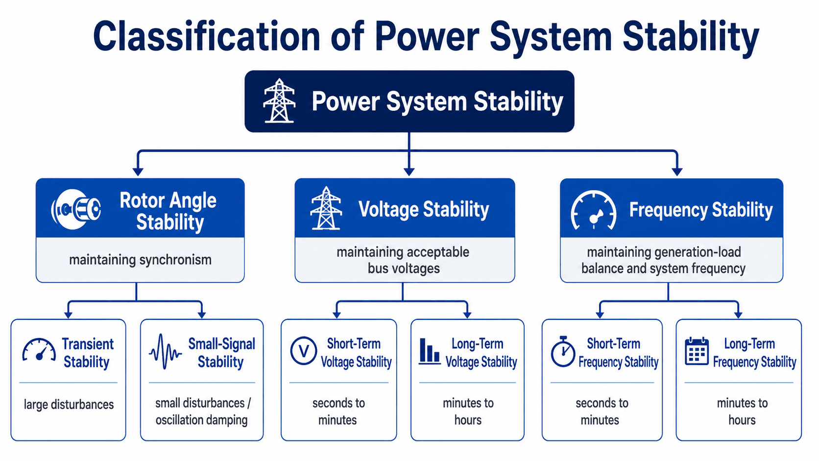
Use this diagram as the map for the rest of the page. Rotor angle stability is about synchronism, voltage stability is about acceptable bus voltages, and frequency stability is about matching generation and load after a disturbance.
What Is Power System Stability?
Section goal: Understand power system stability as a dynamic grid response problem, not just a steady-state power flow condition.
Power system stability describes how an electrical grid responds after something changes. That change may be a short circuit, line trip, large motor start, sudden load increase, generator outage, inverter control action, or renewable generation swing. A stable system does not mean nothing moves. It means the system variables move in a controlled way and settle back into acceptable operation.
The key practical idea is that stability is dynamic. A load flow analysis may show acceptable steady-state voltage and equipment loading, but it does not prove that the system can survive a fault, recover voltage, damp oscillations, or maintain frequency after a severe disturbance.
A stable operating point is not just a solved case. Engineers also need to know how much margin exists before a rotor angle swing, voltage drop, or frequency deviation becomes unacceptable.
Main Types of Power System Stability
Classification logic: Stability is grouped by the physical variable that becomes unstable, the size of the disturbance, and the time frame of the response.
Stability problems are easier to understand when they are grouped by the variable that fails first. In a large interconnected grid, the same event can affect rotor angle, voltage, and frequency at the same time, but one mechanism usually drives the primary instability.
| Stability type | Primary concern | Typical disturbance | What engineers review |
|---|---|---|---|
| Rotor angle stability | Synchronous generators remaining in synchronism | Faults, line trips, generator trips, high power transfer | Rotor angle separation, damping, critical clearing time, synchronizing torque |
| Voltage stability | Maintaining acceptable bus voltages after changes in load or network conditions | Reactive power shortage, weak grid, heavy transfer, delayed voltage recovery | Voltage recovery, reactive reserve, PV/QV behavior, transformer taps, load response |
| Frequency stability | Maintaining generation-load balance across the system | Loss of generation, load rejection, islanding, low-inertia operation | Frequency nadir, rate of change of frequency, governor response, load shedding |
Rotor Angle Stability
Rotor angle stability is the ability of synchronous machines to remain in step with the rest of the system. After a fault or sudden power transfer change, generator rotors accelerate or decelerate. If the electrical and mechanical torque balance can recover, the rotor angle swings decay. If the swing grows too large, the generator can lose synchronism.
Voltage Stability
Voltage stability is the ability of the system to maintain acceptable bus voltages after a disturbance. It is strongly tied to reactive power support, load behavior, transformer tap action, line impedance, and how close the system is operating to voltage collapse.
Frequency Stability
Frequency stability is the ability of the system to maintain frequency after a generation-load imbalance. When generation is suddenly lost, frequency falls. The system response depends on inertia, governor response, inverter controls, load relief, and underfrequency load shedding.
Older textbooks may use terms such as steady-state stability, transient stability, and dynamic stability. Modern classification is usually more precise because it identifies the main instability mechanism: rotor angle, voltage, or frequency.
Stability Categories by Disturbance Size and Time Scale
Time scale matters because different instability mechanisms appear at different speeds. A first-swing rotor angle problem may appear within seconds, while some voltage stability problems involve slower controls such as transformer tap changers, generator reactive limits, or load restoration.
| Category | Disturbance size | Typical time frame | Typical study method |
|---|---|---|---|
| Transient rotor angle stability | Large disturbance | First few seconds after a fault or switching event | Time-domain dynamic simulation |
| Small-signal rotor angle stability | Small disturbance | Seconds to tens of seconds | Modal or eigenvalue analysis, damping review |
| Short-term voltage stability | Small or large disturbance | Seconds to minutes | Dynamic simulation with motor loads, exciters, and inverter controls |
| Long-term voltage stability | Small or large disturbance | Minutes to hours | Long-term dynamic simulation, PV/QV review, reactive margin checks |
| Frequency stability | Large generation-load imbalance | Seconds to minutes | Frequency response simulation and underfrequency load shedding review |
Stable vs. Unstable System Response
A stable response is usually not perfectly flat. The system may oscillate, voltage may dip, and frequency may move away from nominal. The important question is whether those movements are self-correcting and return to acceptable limits.
The shape of the response matters more than the first movement. A stable system may move sharply at first, but the response must damp, recover, or settle before equipment trips or operating limits are violated.
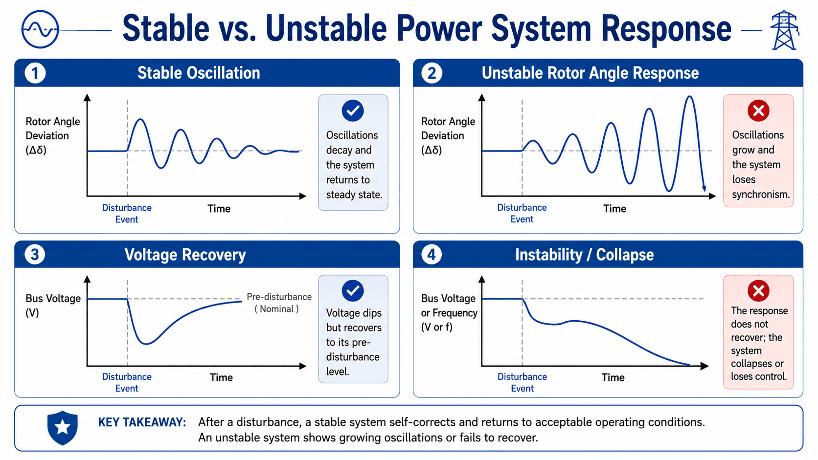
What Stable Response Looks Like
A stable rotor angle response has damping. The first swing may be large, but later swings are smaller. A stable voltage response may dip during a fault or motor acceleration event, but it recovers to an acceptable range. A stable frequency response may fall after a generation loss, but it reaches a nadir and begins recovering.
What Unstable Response Looks Like
An unstable response does not settle. Rotor angle swings may grow until synchronism is lost. Bus voltage may continue declining because reactive support is insufficient. Frequency may keep falling if generation and load are not rebalanced quickly enough.
Symptoms of Power System Instability
Stability problems are often recognized by the shape of the response curves. Engineers review rotor angle, voltage, frequency, relay operation, and controller response together because one instability mode can trigger another.
| Observed symptom | Likely stability issue | What engineers check |
|---|---|---|
| Growing rotor angle swings | Rotor angle instability | Damping, clearing time, transfer level, synchronizing torque, generator controls |
| Voltage dips and does not recover | Short-term or long-term voltage instability | Reactive reserve, motor load behavior, weak buses, transformer taps, generator VAR limits |
| Frequency continues falling | Frequency instability | Inertia, governor response, inverter frequency support, generation loss, load shedding |
| Low-frequency oscillations persist | Small-signal stability problem | Interarea modes, local plant modes, damping ratio, power system stabilizer tuning |
| Plant trips during recoverable events | Control or protection coordination issue | Ride-through settings, relay logic, inverter current limits, plant controller behavior |
Key Equations Behind Rotor Angle Stability
Section goal: Use simplified equations to build intuition for why inertia, accelerating power, rotor angle, and clearing time affect synchronism.
Rotor angle stability is often introduced with the swing equation and the power-angle relationship. These equations are simplified compared with a full dynamic simulation, but they explain why inertia, accelerating power, electrical power transfer, and rotor angle margin matter.
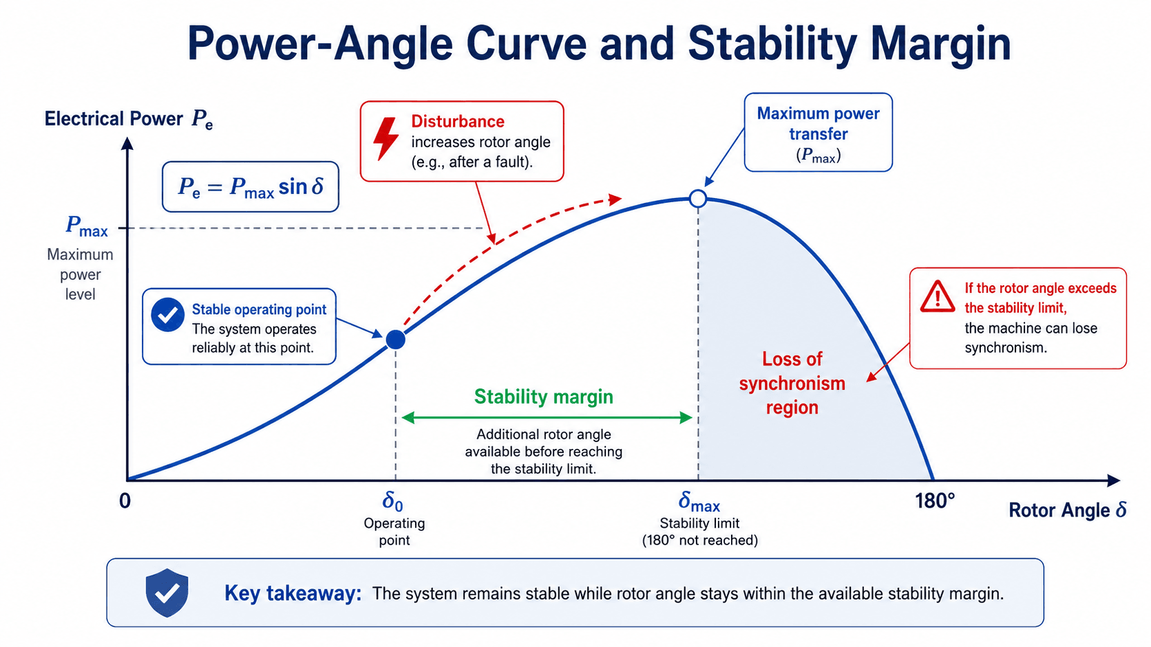
The swing equation says that rotor acceleration depends on the difference between mechanical input power \(P_m\) and electrical output power \(P_e\). If mechanical power is greater than electrical power, the rotor accelerates. If electrical power is greater, it decelerates.
The simplified power-angle curve shows that transferable electrical power increases with rotor angle up to a maximum value. Past the stability limit, increasing rotor angle no longer produces a stronger restoring effect, and the machine can move toward loss of synchronism.
The power-angle curve is not a full dynamic simulation, but it gives useful intuition for why clearing time and rotor angle margin matter. A disturbance pushes the rotor angle toward larger values; the system remains stable only if the swing stays within the available margin and then decelerates.
- \(\delta\) Rotor angle, usually interpreted as the angular separation between a machine internal voltage and a reference.
- \(M\) Inertia-related constant that affects how quickly rotor speed and angle change after a disturbance.
- \(P_m\) Mechanical input power from the prime mover, such as a turbine or engine.
- \(P_e\) Electrical power transferred from the generator into the power system.
- \(P_{max}\) Maximum transferable electrical power under the simplified power-angle relationship.
Common Causes of Power System Instability
Instability usually comes from a loss of margin. The system may be operating too close to a transfer limit, voltage limit, reactive power limit, frequency-response limit, or controller/protection boundary. The disturbance exposes that weak point.
| Cause | Stability effect | Practical example |
|---|---|---|
| Slow fault clearing | Rotor angle swings grow before the system can recover | Breaker clearing time exceeds the critical clearing time for a nearby generator |
| Weak reactive support | Bus voltage dips and fails to recover | A remote load pocket has limited local VAR support after a line outage |
| Poor oscillation damping | Rotor angle or power oscillations persist or grow | Heavy interarea transfer creates a low-frequency mode with poor damping |
| Large generation-load imbalance | Frequency falls too quickly or reaches an unacceptable nadir | A large generator trips in a low-inertia islanded system |
| Low system strength | Voltage and inverter controls may interact poorly | An inverter-based resource plant connects to a weak transmission node |
| Incorrect protection or control settings | Recoverable events can become cascading trips | Plant protection trips during a voltage ride-through event that should have been tolerated |
How Engineers Analyze Power System Stability
Engineering workflow: Build a credible operating case, apply realistic disturbances, run the right dynamic study, and interpret whether the response remains acceptable.
Power system stability analysis is normally a modeling workflow, not a single hand calculation. Engineers build a credible operating case, apply disturbances, run dynamic simulations or specialized studies, and review whether the system response stays within acceptable limits.
| Study activity | What it checks | Typical stability insight |
|---|---|---|
| Base-case power flow | Voltage profile, equipment loading, MW/MVAR flows, reactive margins | Defines the initial operating condition before the disturbance is applied. |
| Transient stability simulation | Generator rotor angle swings after faults, trips, and clearing events | Shows whether machines remain synchronized after large disturbances. |
| Small-signal stability analysis | Oscillation modes, damping ratios, local and interarea modes | Shows whether small disturbances decay or create sustained oscillations. |
| Voltage stability review | Voltage recovery, reactive power support, weak-bus behavior, PV/QV curves | Shows whether voltage can recover under stressed transfer or load conditions. |
| Frequency response study | Frequency nadir, rate of change of frequency, governor response, load shedding | Shows whether the system can rebalance generation and load fast enough. |
The most important stability study input is often the operating case. Dispatch, line status, load level, reactive reserve, inertia, and protection clearing time can change the conclusion.
Choosing the Right Stability Study Method
Different study methods answer different stability questions. A transient stability simulation is not the same as a small-signal modal study, and a voltage stability margin review is not the same as a frequency response study.
| Method | Best for | Main output | Common mistake |
|---|---|---|---|
| Time-domain dynamic simulation | Transient rotor angle, voltage recovery, frequency response | Rotor angle, voltage, frequency, power, and controller traces over time | Running too few contingencies or using unrealistic clearing times |
| Eigenvalue or modal analysis | Small-signal stability and oscillation damping | Modes, damping ratios, frequencies, and participation factors | Ignoring operating point sensitivity or controller tuning assumptions |
| PV curve review | Voltage stability loading margin | Maximum loading point and voltage collapse margin | Treating a static margin as proof of dynamic voltage recovery |
| QV curve review | Reactive power margin at weak buses | Reactive reserve requirement and voltage support sensitivity | Missing reactive limits or nearby control interactions |
| EMT simulation | Fast inverter, converter, protection, and control interactions | High-resolution electromagnetic transient behavior | Using EMT only after issues appear instead of when controls are known to be fast or weak-grid-sensitive |
What Controls Power System Stability?
Stability margin is controlled by a combination of network strength, equipment dynamics, protection speed, control tuning, and operating conditions. A system with strong steady-state voltage can still have poor damping, weak frequency response, or limited transient margin.
| Controlling factor | Why it matters | Engineering implication |
|---|---|---|
| Fault clearing time | Longer fault duration gives rotor angles more time to separate. | Protection settings and breaker performance can determine whether the first swing remains stable. |
| Reactive power support | Voltage recovery depends on local reactive capability and network impedance. | Capacitors, reactors, STATCOMs, SVCs, generator excitation, and inverter VAR control may be needed. |
| System inertia | Inertia slows frequency and rotor-speed changes after imbalance. | Low-inertia systems may require faster frequency response, storage, inverter controls, or operating limits. |
| Oscillation damping | Poor damping can allow small disturbances to persist or grow. | Power system stabilizers, controller tuning, and transfer limits may be reviewed. |
| Operating point | Heavy transfers and stressed voltage profiles reduce available margin. | The same grid can be stable in a light-load case and unstable in a high-transfer case. |
| Inverter controls | Fast electronic controls shape voltage, current, and frequency response. | Model validation and control coordination are critical for high inverter-based resource penetration. |
How Engineers Improve Power System Stability
Improving stability usually means increasing margin, reducing disturbance severity, speeding up corrective action, or improving damping and voltage/frequency support. The correct fix depends on which stability mechanism is limiting the system.
| Improvement method | Stability issue addressed | How it helps |
|---|---|---|
| Faster fault clearing | Transient rotor angle stability | Reduces acceleration time during faults and improves critical clearing margin. |
| Power system stabilizers | Small-signal oscillation damping | Adds damping torque through excitation control to reduce sustained oscillations. |
| Reactive compensation | Voltage stability | Provides local VAR support so bus voltages recover after faults and load changes. |
| Transfer limits and re-dispatch | Rotor angle and voltage margin | Moves the system away from stressed operating points and heavily loaded corridors. |
| Governor response and fast frequency response | Frequency stability | Helps arrest frequency decline after generation-load imbalance. |
| Underfrequency load shedding | Severe frequency instability | Disconnects load in stages when frequency falls below defined thresholds. |
| Inverter ride-through and control tuning | Modern grid voltage and frequency response | Prevents unnecessary plant trips and coordinates fast inverter response with grid needs. |
Example: Fault Clearing and Transient Stability Margin
Consider a generator exporting power through a transmission corridor. A three-phase fault occurs near one of the lines. During the fault, electrical power transfer drops sharply while mechanical input power from the turbine does not instantly change. The rotor accelerates and the rotor angle increases.
Fast Clearing Case
If protection clears the fault quickly, the transmission path is restored before the rotor angle swing becomes too large. The machine may oscillate, but the oscillations decay and the generator remains synchronized with the system.
Slow Clearing Case
If clearing is delayed, the rotor angle can move beyond the available stability margin. Even after the fault is removed, the generator may not decelerate enough to regain synchronism. This is why critical clearing time is a key output in transient stability studies.
Real transient stability studies do not rely only on the simplified power-angle curve. They include generator models, excitation systems, governors, protection timing, network switching, motor loads, and inverter controls so engineers can judge the actual time-domain response.
Senior Engineer Stability Study Review Checklist
A stability study is only useful when the model and cases represent the real decision being made. The checklist below helps identify whether a study is ready to support planning, interconnection, protection, or operating-limit decisions.
Start with a credible power flow case, confirm dynamic model data, apply realistic disturbances, review response curves, test sensitivity cases, and document the operating limits or corrective actions needed to keep the system stable.
| Study review check | What to look for | Why it matters |
|---|---|---|
| Initial operating case | Realistic dispatch, load level, topology, transformer taps, and reactive devices | Stability depends on the starting condition, not just the disturbance. |
| Dynamic model quality | Generator, exciter, governor, PSS, motor load, inverter, and plant controller models | Bad dynamic models can make a system look stable or unstable for the wrong reason. |
| Fault and clearing assumptions | Fault location, fault type, breaker clearing time, reclosing, and backup clearing | Transient stability is highly sensitive to how long the system remains faulted. |
| Rotor angle and damping | First swing, growing oscillations, interarea modes, and damping ratio trends | Loss of synchronism may occur even when voltage and loading appear acceptable initially. |
| Voltage recovery | Post-fault voltage dip depth, recovery time, reactive reserve, and weak-bus behavior | Delayed or failed voltage recovery can trigger motor stalling, relay trips, or voltage collapse. |
| Frequency response | Frequency nadir, rate of change, governor response, and underfrequency load shedding | Frequency stability depends on how quickly generation and load are rebalanced. |
| Sensitivity cases | High transfer, low inertia, high renewable output, low load, unavailable equipment | A single base case rarely proves adequate stability margin across real operating conditions. |
Modern Grid Stability and Inverter-Based Resources
Modern power systems increasingly include solar PV, wind, battery storage, HVDC terminals, and other inverter-based resources. These resources can support stability when modeled and controlled properly, but they also change the system’s dynamic behavior compared with a grid dominated by synchronous machines.
- Inverter-based resources may contribute limited short-circuit current compared with synchronous machines.
- Frequency response may depend more on control logic, fast active power support, storage availability, and ride-through settings.
- Voltage stability may depend on plant-level reactive power controls, current limits, and the strength of the grid at the point of interconnection.
- Fast controls can interact with weak networks, other inverters, filters, or protection settings if they are not represented correctly in the model.
A renewable plant should not be judged only by its MW output. For stability, engineers also review voltage control mode, reactive capability, ride-through behavior, frequency response, plant controller settings, and whether the model matches tested equipment behavior.
For broader background on local generation and renewable integration, see Distributed Generation Systems and Stand-Alone Power Systems.
When This Breaks Down
Simplified stability explanations are useful for learning, but they can break down when the actual system response is controlled by detailed protection actions, nonlinear loads, inverter limits, saturation, control interactions, or changing topology.
- Single-machine intuition is not enough: Multi-machine systems can include local plant modes, interarea oscillations, and interactions between distant areas.
- Steady-state voltage does not prove voltage stability: A bus may look acceptable in a load flow but still fail to recover after a fault or reactive power limit is reached.
- Nominal frequency does not prove frequency resilience: Frequency response depends on the disturbance size, available inertia, governor response, inverter controls, and load shedding.
- Generic dynamic models can mislead: Default generator, exciter, governor, motor, or inverter models may not represent the installed equipment or actual control settings.
- Protection can dominate the outcome: Relay timing, reclosing, load shedding, and plant trips can decide whether the system recovers or cascades.
Common Mistakes and Practical Checks
Power system stability mistakes often come from treating a dynamic problem as a static one. The goal is not just to solve a model, but to understand whether the modeled behavior is credible and whether the conclusion can support a real engineering decision.
- Stopping at load flow: A converged steady-state case does not show rotor swings, frequency nadir, or voltage recovery.
- Ignoring reactive limits: Voltage support may disappear when generators, inverters, or compensators reach their reactive capability limits.
- Using one operating case: Stability margins can change significantly with dispatch, load level, outages, renewable output, and transfer level.
- Overlooking damping: A system that survives the first swing can still be unacceptable if oscillations are poorly damped.
- Trusting unvalidated inverter models: Fast control behavior must be represented accurately when inverter-based resources are important to the system response.
Do not describe a system as stable just because it survives one simulated fault. Review damping, voltage recovery, frequency response, protection actions, and sensitivity cases before drawing a conclusion.
Power System Stability vs. Reliability and Security
Stability, reliability, and security are related, but they are not identical. Stability focuses on whether the system response remains acceptable after a disturbance. Reliability is broader and includes the ability to deliver electricity over time. Security focuses on whether the system can withstand credible contingencies without violating operating limits.
In practice, stability studies often support reliability and security decisions. A system may be secure for one contingency but unstable for another, especially when operating conditions, protection settings, or dynamic models change.
Engineering References and Stability Classification Guidance
Power system stability terminology should follow recognized classification guidance because the same word can mean different things in planning, operations, protection, and dynamic modeling work.
- IEEE/CIGRE stability classification: Definition and Classification of Power System Stability is a useful reference for the formal classification of rotor angle stability, voltage stability, frequency stability, disturbance size, and stability time scales.
- Project-specific criteria: Utility interconnection requirements, owner criteria, protection philosophy, generator data, inverter model requirements, and reliability standards may control the final acceptance criteria for a specific study.
- Engineering use: Engineers use classification guidance to define the study type correctly before selecting cases, disturbances, models, time windows, and acceptable response criteria.
Frequently Asked Questions
Power system stability is the ability of an electric power system to maintain or regain an acceptable operating equilibrium after a disturbance such as a fault, generator trip, load change, or transmission outage.
The main types are rotor angle stability, voltage stability, and frequency stability. Rotor angle stability is about maintaining synchronism, voltage stability is about maintaining acceptable bus voltages, and frequency stability is about maintaining generation-load balance.
Transient stability deals with large disturbances such as short circuits, line trips, or sudden generator loss. Small-signal stability deals with small disturbances around an operating point and focuses heavily on whether oscillations are adequately damped.
Engineers improve stability with faster fault clearing, proper protection settings, excitation control, power system stabilizers, reactive power support, operating limits, dispatch changes, load shedding schemes, and correctly tuned inverter controls.
Inverter-based resources can change system inertia, short-circuit strength, voltage control behavior, and frequency response. They are not automatically unstable, but their controls and models must be reviewed carefully in dynamic studies.
Summary and Next Steps
Power system stability explains whether an electric power system can recover after a disturbance while maintaining synchronism, acceptable voltage, and controlled frequency. It is one of the core ideas behind reliable grid planning, interconnection studies, protection review, and operating-limit development.
The most important practical checks are rotor angle damping, voltage recovery, frequency response, protection clearing time, reactive reserve, dynamic model quality, and sensitivity to operating conditions. A credible stability conclusion depends on both good engineering judgment and a realistic model.
Where to go next
Continue your learning path with related Turn2Engineering resources.
-
Load Flow Analysis
Learn how steady-state operating cases are built before dynamic stability studies are performed.
-
Introduction to Power Engineering
Build the foundation for understanding generation, transmission, distribution, and grid operation.
-
Distributed Generation Systems
Explore how local generation, renewable resources, and grid integration affect modern power systems.