Key Takeaways
- Core idea: Transmission line protection detects faults and trips the correct breakers so the faulted line section is removed without unnecessarily de-energizing healthy equipment.
- Engineering use: Protection engineers use distance, differential, directional overcurrent, pilot, and backup schemes to balance speed, selectivity, dependability, sensitivity, and security.
- What controls it: Relay settings depend on line impedance, source strength, fault current, loadability, instrument transformer accuracy, breaker performance, and communication availability.
- Practical check: A good scheme must trip for real faults while staying secure during heavy loading, power swings, CT saturation, weak infeed, and communication-channel problems.
Table of Contents
Introduction
Transmission line protection is the coordinated use of protective relays, instrument transformers, circuit breakers, communication channels, and backup logic to detect faults on high-voltage lines and isolate the affected section. Its job is not simply to trip fast; it must trip the right breakers, preserve system stability, and avoid unnecessary outages.
Transmission Line Protection Schemes at a Glance
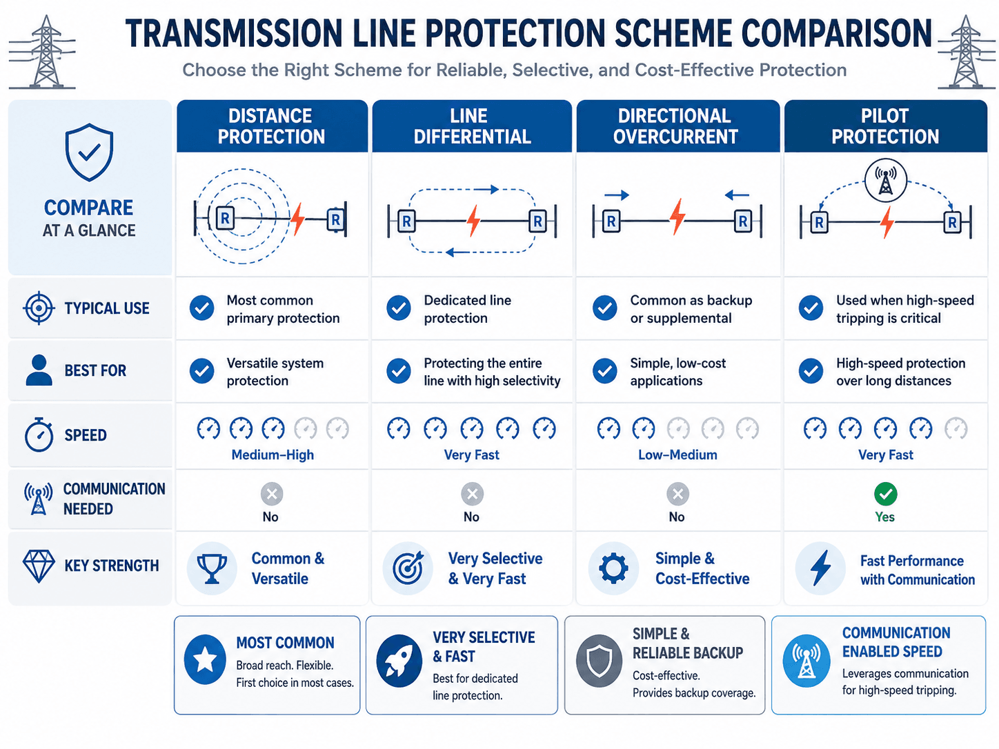
Notice that no single scheme is automatically best for every line. Distance protection is common and versatile, line differential is highly selective and normally communication-dependent, directional overcurrent is often a simpler backup approach, and pilot protection uses communication to improve speed and selectivity.
What is Transmission Line Protection?
Transmission line protection is the part of power system protection focused on detecting abnormal electrical conditions on overhead or underground transmission circuits. When a short circuit, ground fault, phase fault, or other severe disturbance occurs, the protection system decides whether the fault is inside the protected zone and sends a trip command to one or more circuit breakers.
The engineering challenge is selectivity. A relay must operate quickly when the fault is on the protected line, but it must remain secure for faults outside its zone, heavy load, switching events, stable power swings, and measurement errors. That balance between speed, dependability, and security is why transmission line protection is more than a simple overcurrent trip.
A transmission protection system should isolate the faulted line section with minimum disruption to the rest of the grid. Fast tripping matters, but correct tripping matters more.
Protection Quality: Speed, Selectivity, Sensitivity, Dependability, and Security
A strong transmission line protection scheme is judged by more than whether it operates. It must operate for the correct faults, avoid operating for external or non-fault conditions, and coordinate with other protection layers on the system.
| Protection quality | Meaning | Transmission line example |
|---|---|---|
| Speed | How quickly the fault is cleared after detection. | High-speed tripping reduces equipment stress and helps preserve transient stability on important high-voltage corridors. |
| Selectivity | The correct device trips while healthy equipment remains energized. | A line relay trips the breakers for the faulted line, not a neighboring unfaulted line. |
| Sensitivity | The relay can detect faults even when the electrical signature is weak. | Ground elements may need enough sensitivity for high-resistance ground faults. |
| Dependability | The protection operates when it should for an actual fault. | Backup protection operates if the primary relay, trip circuit, or breaker does not clear the fault. |
| Security | The protection does not operate when it should not. | Distance protection remains stable during heavy loading, external faults, and stable power swings. |
Faults Transmission Line Protection Must Detect
Transmission line faults vary by phase involvement, ground involvement, resistance, and system conditions. Protection must be sensitive enough to detect credible line faults while remaining secure for external faults and non-fault disturbances.
| Fault type | What happens | Protection concern |
|---|---|---|
| Single-line-to-ground fault | One phase contacts ground through an arc, object, structure, or failed insulation path. | Ground distance, directional ground overcurrent, and zero-sequence compensation may be important. |
| Line-to-line fault | Two phases fault together without direct ground involvement. | Phase distance or phase overcurrent elements must detect the phase fault securely. |
| Double-line-to-ground fault | Two phases fault to ground, often with unbalanced current and voltage behavior. | Relay logic must correctly classify the fault and avoid directional or reach errors. |
| Three-phase fault | All three phases are faulted together. | This is severe and usually easy to detect, but it can create high mechanical and thermal stress. |
| High-resistance ground fault | Fault current is limited by arc resistance, soil conditions, vegetation, or contact impedance. | Reduced current and increased apparent impedance can cause underreach or delayed detection. |
Main Components of a Transmission Line Protection System
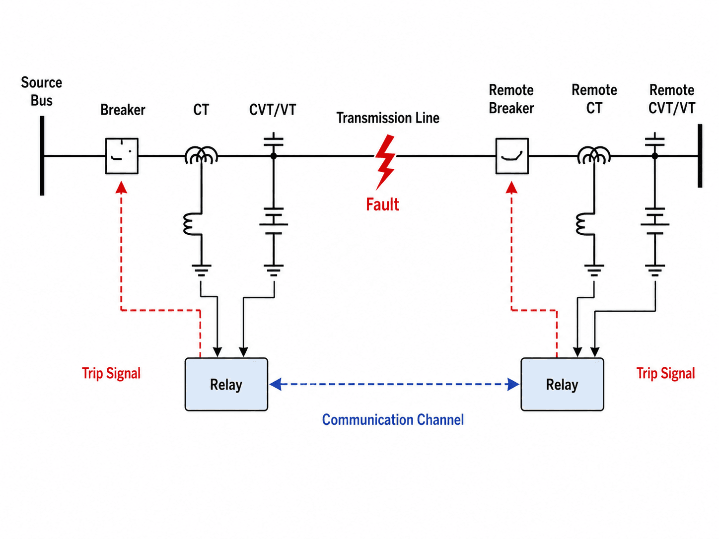
A line protection scheme uses measurements from both the local terminal and, in many cases, the remote terminal. Current transformers provide current signals, voltage transformers or CVTs provide voltage signals, protective relays make the operating decision, and circuit breakers physically interrupt the fault current.
| Protection component | What it does | Why it matters for transmission lines |
|---|---|---|
| Current transformer (CT) | Steps line current down to a measurable relay input. | CT saturation, ratio errors, or polarity mistakes can distort fault current and affect relay security. |
| Voltage transformer / CVT | Provides line voltage information for distance and directional elements. | Distance relays depend on voltage and current together to estimate apparent impedance. |
| Protective relay | Applies logic such as distance, differential, directional, overcurrent, pilot, or breaker failure protection. | The relay decides whether the fault is inside the protected zone and whether to trip. |
| Circuit breaker | Interrupts fault current after receiving a trip command. | Breaker speed and breaker failure logic affect total clearing time and backup protection behavior. |
| Trip circuit | Carries the relay trip command to the breaker trip coil. | A relay can operate correctly but still fail to clear the fault if the trip path fails. |
| Communication channel | Allows terminal relays to exchange permissive, blocking, transfer-trip, or differential information. | Communication can make line protection faster and more selective, especially on important or long lines. |
Main Transmission Line Protection Schemes
Transmission lines are usually protected with more than one function. A common arrangement may use distance protection as primary protection, pilot logic for high-speed tripping, directional overcurrent as backup, and breaker failure logic to handle a breaker that does not open.
| Protection scheme | Common relay function | Typical role | Main limitation |
|---|---|---|---|
| Distance protection | 21 | Primary or backup line protection using apparent impedance. | Can be affected by fault resistance, load encroachment, power swings, mutual coupling, and weak infeed. |
| Line current differential protection | 87L | Unit protection that compares current entering and leaving the protected line. | Normally requires reliable high-speed communication and careful treatment of CT performance and channel behavior. |
| Directional overcurrent protection | 67, 67N | Backup or supplemental protection using current magnitude and direction. | May be slower or less selective than distance or differential protection in meshed networks. |
| Overcurrent protection | 50/51, 50N/51N | Supplemental or backup current-based protection. | Fault current magnitude can change significantly with system configuration and source strength. |
| Pilot protection | POTT, DCB, DTT, permissive/blocking logic | Communication-assisted protection for high-speed terminal clearing. | Performance depends on communication-channel reliability and correct logic coordination. |
| Breaker failure protection | 50BF | Backup logic that trips adjacent breakers if the intended breaker fails to clear. | Must be coordinated carefully to avoid excessive equipment outage during backup operation. |
Distance protection
Distance protection of a transmission line uses apparent impedance to estimate whether a measured fault falls within a configured reach zone. The relay does not literally measure distance in miles or kilometers; it measures the relationship between voltage and current and compares it with line impedance-based settings.
Line differential protection
Modern line differential protection normally requires a high-speed communication channel between line terminals so relay currents can be compared across the protected line zone. When the current entering and leaving the line does not balance within the relay logic, the scheme can identify an internal line fault very quickly.
Directional overcurrent and pilot protection
Directional overcurrent elements add directional awareness to current-based protection, which helps in networked systems where fault current can flow from more than one source. Pilot protection uses communication between terminals through schemes such as permissive overreaching transfer trip, directional comparison blocking, and direct transfer trip to improve speed and selectivity.
How Engineers Select a Transmission Line Protection Scheme
Protection scheme selection depends on the line, not just the relay catalog. Engineers consider voltage level, line length, source strength, network topology, communication availability, fault-clearing speed, backup requirements, and how critical the line is to system reliability.
| Line or system condition | Preferred protection direction | Reason |
|---|---|---|
| Long high-voltage line with known impedance | Distance protection with coordinated backup zones | Line impedance provides a practical basis for reach settings and remote backup. |
| Critical line requiring high-speed terminal clearing | Pilot protection or line current differential | Communication-assisted schemes can trip both terminals faster and more selectively. |
| Dedicated two-terminal line with reliable communication | Line differential protection | The protected zone is well defined, and current comparison can be highly selective. |
| Simpler application or supplemental backup | Directional overcurrent or time-overcurrent backup | Current-based protection can provide economical backup when coordinated with primary schemes. |
| Communication channel is unreliable or unavailable | Distance protection with time-delayed backup | The line still needs dependable fault coverage without fully relying on a communication channel. |
| Heavy loading near relay reach characteristics | Distance protection with load encroachment and loadability checks | Relay security must be checked so acceptable loading does not look like a fault. |
Distance Relay Zones on a Transmission Line
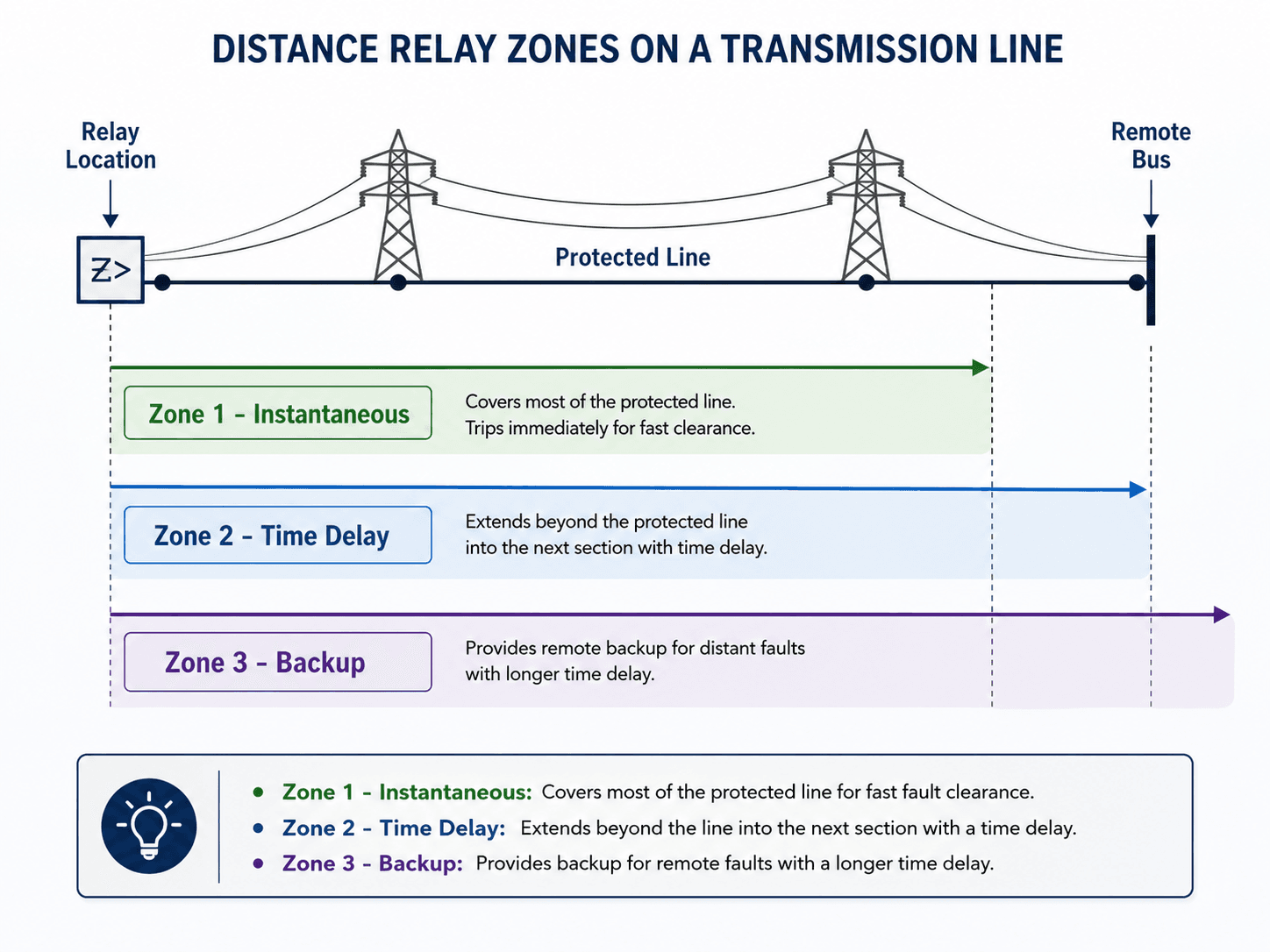
Distance relays usually apply multiple zones of protection. Each zone has a reach and a time delay. This lets the relay provide fast protection for most of the protected line while also giving time-delayed backup for the remote end of the line or adjacent line sections.
Zone 1
Zone 1 is usually the fastest distance element. It is set to cover most of the protected line but normally not all of it, because measurement error, line-parameter uncertainty, and remote-end effects can cause overreach if it is set too aggressively.
Zone 2
Zone 2 typically reaches beyond the protected line into the next section and operates with a time delay. It can cover the remaining end of the protected line and provide backup for part of the adjacent line.
Zone 3
Zone 3 is generally a remote backup zone with a longer time delay, but it must be applied carefully. Long-reaching distance elements can be vulnerable to load encroachment and stable power swings, so some utilities reduce, supervise, or avoid certain Zone 3 applications depending on their protection philosophy and reliability requirements.
Primary Protection vs Backup Protection
Transmission line protection is layered so one failure does not leave a fault energized indefinitely. Primary protection is intended to clear the faulted line first. Backup protection operates if the primary relay, breaker, trip circuit, communication channel, or DC control circuit does not perform as expected.
| Protection layer | Purpose | Typical transmission line example |
|---|---|---|
| Primary protection | Trips the faulted line section as quickly and selectively as possible. | Zone 1 distance, line differential, or pilot-assisted tripping for an internal line fault. |
| Local backup | Operates from the same substation if primary protection or breaker clearing does not succeed. | Breaker failure protection trips adjacent breakers when the intended breaker fails. |
| Remote backup | Operates from a remote terminal or neighboring substation after a delay. | Zone 2 or Zone 3 distance elements clear faults that were not cleared by closer protection. |
| Communication-assisted backup | Uses terminal-to-terminal information to improve speed or selectivity. | Pilot or transfer-trip logic helps both line ends respond to confirmed internal faults. |
How a Transmission Line Fault Is Cleared
Fault clearing is a sequence, not a single event. The relay receives current and voltage signals, evaluates whether the event is inside the protected zone, checks its logic, and sends a trip command to the breaker. If the primary protection or breaker fails, backup protection must remove the fault without creating a larger outage than necessary.
Fault occurs on the line → CT and voltage inputs change → relay identifies the fault type and direction → distance, differential, overcurrent, or pilot logic determines whether the fault is internal → trip signal is issued → breaker opens → remote terminal trips if required → backup or breaker failure logic operates if the primary action fails.
| Fault-clearing step | What happens | Engineering concern |
|---|---|---|
| Fault inception | A line-to-ground, line-to-line, or three-phase fault changes current and voltage abruptly. | High-resistance faults may produce lower current and can be harder to detect securely. |
| Measurement | CTs and voltage transformers send scaled signals to the relay. | Instrument transformer accuracy and saturation affect relay decision quality. |
| Relay decision | The relay applies protection elements and logic to classify the event. | Settings must distinguish an internal fault from load, external faults, swings, or switching events. |
| Breaker trip | The relay energizes the trip circuit and the breaker interrupts fault current. | Breaker interrupting time and breaker failure logic affect total clearing time. |
| Backup action | Time-delayed local or remote backup operates if the primary path fails. | Backup must be dependable without causing unnecessary cascading trips. |
Protection Setting Inputs Engineers Review
Transmission line relay settings are developed from system studies, line data, equipment ratings, operating practices, and protection philosophy. The relay setting is only as good as the assumptions behind it.
| Setting input | Why it matters | Engineering implication |
|---|---|---|
| Positive- and zero-sequence line impedance | Distance elements use impedance to estimate whether a fault is inside the protected reach. | Wrong line parameters can cause overreach, underreach, or poor ground-fault coverage. |
| Source strength at each terminal | Fault current magnitude and direction depend on the network behind each terminal. | Weak infeed can make remote-end detection and permissive logic more difficult. |
| Maximum load and emergency loading | Load current and apparent impedance can move closer to relay operating characteristics. | Load encroachment checks help avoid tripping for heavy but acceptable operating conditions. |
| CT and VT/CVT ratios and accuracy | Relay calculations depend on accurate secondary measurements. | Incorrect ratios, polarity errors, saturation, or transient response issues can affect relay security. |
| Breaker clearing time | Total fault clearing time includes relay operating time plus breaker interrupting time. | Coordination margins must allow the correct protection to operate before backup protection trips more equipment. |
| Communication channel availability | Pilot and line differential schemes depend on terminal-to-terminal communication. | Engineers must define how the scheme behaves when the channel is delayed, degraded, or unavailable. |
Apparent Impedance in Distance Protection
A distance relay compares measured voltage and current to estimate apparent impedance between the relay location and the fault. This makes the relay less dependent on fault current magnitude alone, which is one reason distance protection is common on transmission lines.
If the apparent impedance falls inside a configured relay zone, the relay may issue a trip depending on the zone delay, fault type, directional supervision, and other blocking or permissive logic. The practical idea is simple: a close-in fault usually appears as a smaller impedance than a remote fault.
- \(Z_{\text{app}}\) Apparent impedance seen by the relay, usually expressed in ohms secondary or primary depending on the setting context.
- \(V_{\text{relay}}\) Measured voltage supplied to the relay from a VT or CVT.
- \(I_{\text{relay}}\) Measured current supplied to the relay from CTs.
Simple Distance Relay Interpretation Example
Suppose a transmission line has a simplified positive-sequence impedance of \(0.5 \ \Omega/\text{mile}\), and the relay sees an apparent impedance of \(30 \ \Omega\) during a fault. A simplified distance estimate is:
If the protected line is 100 miles long and Zone 1 is set to cover about 80% of the line, this simplified result would appear inside the Zone 1 reach. In real relay work, the final decision also depends on fault type, ground compensation, source infeed, fault resistance, relay characteristic shape, and supervision logic.
Apparent impedance is not a perfect fault-location measurement. Fault resistance, infeed from the remote terminal, mutual coupling, load current, and power swings can move the measured impedance away from the ideal textbook value.
Transmission Line Protection vs Distribution Feeder Protection
Transmission line protection is often confused with distribution feeder protection, but the engineering priorities are different. Transmission lines are usually part of a networked high-voltage grid, while distribution feeders are often radial circuits serving loads downstream.
| Comparison point | Transmission line protection | Distribution feeder protection |
|---|---|---|
| Typical system role | Moves bulk power across the grid between substations and regions. | Delivers power from substations to local loads. |
| Network behavior | Often meshed, multi-source, and sensitive to stability concerns. | Often radial, although modern distribution systems may include automation and distributed generation. |
| Common protection | Distance, line differential, pilot, directional overcurrent, and breaker failure schemes. | Overcurrent relays, reclosers, fuses, sectionalizers, and feeder automation. |
| Clearing objective | Fast, selective isolation to preserve grid stability and avoid cascading outages. | Coordinated clearing that balances service continuity, fuse saving, and feeder segmentation. |
| Communication use | Common for pilot protection and line differential protection on critical circuits. | Used in advanced feeder automation, but many basic feeder schemes remain local-current based. |
Senior Engineer Review Checklist for Line Protection
A transmission line protection review should check more than whether the relay has a reasonable pickup or reach setting. The scheme must be evaluated as a complete system: measurement inputs, relay logic, trip paths, communication, backup coverage, and operating constraints.
| Review check | What to look for | Why it matters |
|---|---|---|
| Protected zone definition | Confirm which breakers, buses, and line terminals define the protected line section. | Unclear boundaries can lead to gaps, overlap confusion, or unintended trips. |
| Primary and backup coverage | Verify which function clears internal faults first and which functions provide backup if it fails. | Dependable backup coverage prevents a single relay or breaker failure from leaving the fault energized. |
| Zone reach and timing | Check Zone 1, Zone 2, and Zone 3 reach against line length, adjacent lines, and coordination margins. | Incorrect reach can cause underreach for internal faults or overreach into neighboring circuits. |
| Loadability and load encroachment | Compare relay characteristics with expected maximum and emergency loading. | Protection should not become the limiting element for acceptable transmission loading. |
| Communication-assisted logic | Review permissive, blocking, differential, or transfer-trip logic and channel-failure behavior. | Communication can improve speed, but failed or delayed channels must not create unsafe blind spots. |
| Breaker failure response | Confirm that adjacent breakers trip if the intended breaker fails to interrupt current. | Breaker failure logic protects the grid from a stuck breaker but can expand the outage if poorly coordinated. |
| Event record review | Check oscillography, relay targets, sequence of events, and trip timing after operations. | Event data helps confirm whether the scheme behaved as intended and whether settings need correction. |
Engineering Judgment and Field Reality
Real transmission lines do not behave like ideal textbook circuits. A relay may see contributions from multiple sources, changing system topology, parallel-line coupling, series compensation, evolving faults, or heavy transfers that make a normal load condition look closer to a protection boundary than expected.
Protection engineers often spend as much time checking security as speed. A scheme that trips slightly slower but remains secure during stable swings, high load, and external faults may be far better than a fast scheme that misoperates.
The most important judgment is whether the protection philosophy fits the actual line. A short line near a strong source, a long EHV line, a series-compensated corridor, and a tapped transmission line can require very different protection decisions even if the one-line diagram looks simple.
When This Breaks Down
Simplified explanations of transmission line protection break down when the system no longer behaves like a single source feeding a simple fault through a known line impedance. These conditions can affect relay reach, directionality, sensitivity, and security.
- High-resistance faults: Fault resistance can make the relay see a larger apparent impedance and may cause underreach.
- Heavy load and load encroachment: High transfer levels can move measured impedance near distance relay characteristics.
- Power swings: Stable system swings can look like changing impedance and may require blocking or out-of-step logic.
- CT saturation: Distorted current waveforms can affect overcurrent, differential, and directional decisions.
- Weak infeed: A remote terminal may not supply enough fault current to support expected permissive or directional operation.
- Communication failure: Pilot and differential schemes must have a defined fallback behavior when the channel is unavailable.
Common Mistakes and Practical Checks
Transmission protection problems often come from assuming the relay setting alone defines protection quality. The setting must be checked against system behavior, equipment performance, operating conditions, and backup coordination.
- Treating distance reach as exact fault location: Apparent impedance is affected by fault resistance, source infeed, and system conditions.
- Ignoring loadability: A relay characteristic that overlaps emergency loading can trip the line when operators most need it available.
- Assuming communication is always available: Pilot and differential schemes need secure fallback logic for channel failure or delay.
- Overlooking breaker failure timing: A relay can operate correctly while the fault remains energized if the breaker fails to interrupt.
- Forgetting remote backup coordination: Backup zones must be delayed and coordinated so a remote relay does not trip before the primary scheme has a chance to clear.
Do not evaluate a line relay only at normal topology. Protection should be checked for credible switching states, source changes, adjacent line outages, and heavy transfer conditions.
Reliability Standards and Design Reference Context
Transmission line protection is tied to reliability as well as equipment protection. Relay settings must detect faults, support selective clearing, and avoid unnecessarily limiting the transmission system during normal or emergency operation.
- NERC PRC-023-6: NERC transmission relay loadability requirements explain the reliability objective that protective relay settings should not limit transmission loadability while still detecting fault conditions and protecting the electrical network.
- Project-specific criteria: Utility standards, interconnection requirements, protection philosophies, owner criteria, and regional reliability requirements can control the final scheme and setting approach.
- Engineering use: Protection engineers use reliability guidance together with short-circuit studies, coordination studies, equipment data, and operating procedures to confirm that relay settings are both dependable and secure.
Frequently Asked Questions
Transmission line protection is the coordinated use of relays, instrument transformers, circuit breakers, communication channels, and backup logic to detect faults on high-voltage lines and isolate the affected section quickly and selectively.
Distance relays are widely used for transmission line protection because they estimate whether a fault is within a protected reach using measured voltage and current. Line differential relays, directional overcurrent relays, and pilot schemes are also used depending on the line and system requirements.
Zone 1 is usually the fastest reach for most of the protected line, Zone 2 extends beyond the protected line with a time delay, and Zone 3 provides more remote backup coverage with a longer delay.
Communication allows relays at both line terminals to compare information or send permissive, blocking, or transfer-trip signals. This helps protection operate faster and more selectively than a relay working from local measurements alone.
Misoperation can be caused by incorrect settings, CT saturation, voltage transformer issues, heavy loading, load encroachment, power swings, communication failure, weak infeed, high-resistance faults, or poor coordination between primary and backup protection.
Summary and Next Steps
Transmission line protection detects faults on high-voltage lines and isolates the affected section with coordinated relays, breakers, measurement inputs, communication, and backup logic. The goal is selective fault clearing, not simply fast tripping.
The most important concepts are protection scheme selection, distance relay zones, fault-clearing sequence, setting inputs, loadability, communication-assisted logic, and field conditions that can make a relay misoperate. A strong protection scheme is reviewed as a complete system, from CT inputs through breaker failure backup.
Where to go next
Continue your learning path with related Turn2Engineering power systems resources.
-
Protective Relays
Learn how protective relays detect abnormal conditions and initiate corrective action in power systems.
-
Short-Circuit Analysis
Review how fault currents are calculated for protection, equipment ratings, and system studies.
-
Differential Protection
Explore the current-comparison protection method used for transformers, buses, generators, and transmission lines.