Key Takeaways
- Core idea: Urban power systems are dense electrical networks that move power from transmission supply points through city substations, feeders, transformers, and secondary networks to buildings and critical services.
- Engineering use: Engineers use urban grid planning to manage high load density, outage consequences, voltage control, protection coordination, DER integration, and service continuity in compact built environments.
- What controls it: The most important drivers are load density, feeder capacity, substation spacing, underground cable thermal limits, redundancy, critical loads, hosting capacity, and operating visibility.
- Practical check: A city grid is not reliable just because it is underground or automated; reliability depends on capacity, sectionalizing, protection settings, restoration planning, and field access.
Table of Contents
Introduction
Urban power systems are the electrical networks that generate, receive, distribute, monitor, protect, and manage electricity for cities. They combine substations, medium-voltage feeders, transformers, underground and overhead distribution, smart grid controls, distributed energy resources, storage, and microgrids to serve dense loads where outages can affect buildings, transit, hospitals, water systems, businesses, and public safety.
How an Urban Power System Delivers Electricity
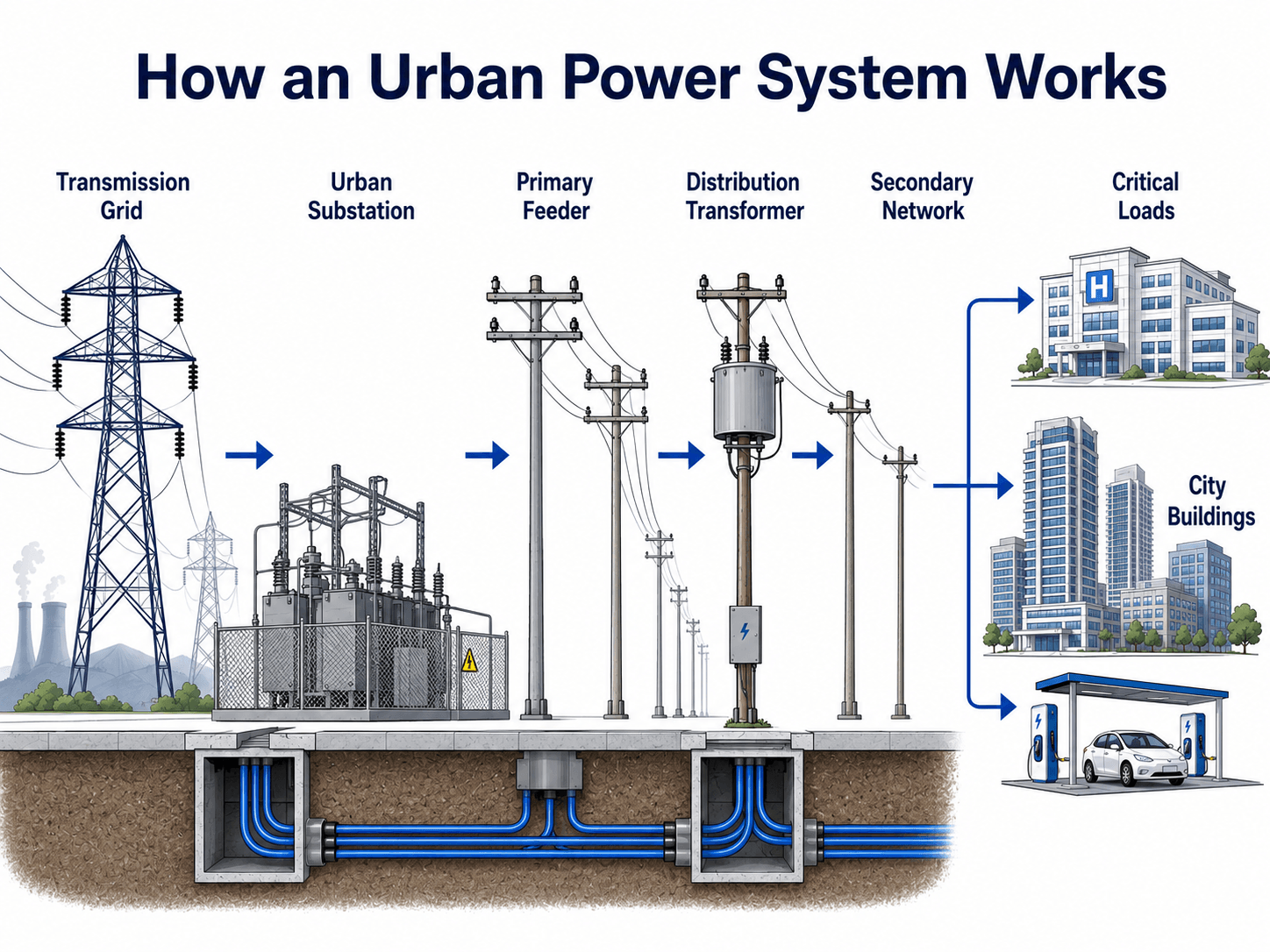
Notice that the city grid is not a single line from a power plant to a building. It is a layered network of voltage levels, switching points, protection zones, underground routes, and load centers.
What Are Urban Power Systems?
An urban power system is the electrical infrastructure used to serve a dense city or metropolitan area. It includes the substations that bring power into the urban load pocket, the distribution feeders that move power through streets and corridors, the transformers that step voltage down near customers, and the control and protection systems that keep faults from spreading.
What makes the urban version different is density. A single downtown feeder may support high-rise buildings, elevators, pumps, data rooms, restaurants, transit equipment, EV chargers, communications systems, and emergency services within a compact area. That load concentration changes how engineers think about capacity, redundancy, maintenance access, protection settings, and outage restoration.
The defining challenge is not only delivering enough electricity. It is delivering enough electricity through limited space while maintaining acceptable voltage, isolating faults quickly, and restoring critical loads when equipment fails.
Main Components in a City Power Grid
Urban power systems are built from familiar power-system components, but those components are arranged closer together, operated with tighter constraints, and often installed in underground vaults, compact substations, utility corridors, and building service rooms.
| Component | Role in an urban power system | Practical engineering concern |
|---|---|---|
| Transmission or subtransmission supply | Brings bulk power toward the city from generation resources or the larger grid. | City supply points need enough capacity and contingency paths for dense load pockets. |
| Urban substations | Step voltage down and divide the city into feeder service areas. | Substation siting is difficult because land, noise, security, access, and permitting are constrained. |
| Primary feeders | Carry medium-voltage power through streets, ducts, utility corridors, or overhead routes. | Feeder loading, thermal limits, and switching options control how much load can be served. |
| Distribution transformers | Step voltage down from primary distribution voltage to service voltage for buildings and local loads. | Transformer overload is common when building redevelopment or EV charging grows faster than utility upgrades. |
| Secondary networks | Distribute lower-voltage power to dense buildings, campuses, and street-level loads. | Network protection and reverse power flow must be handled carefully when DERs are added. |
| Switchgear, breakers, and relays | Detect faults, isolate equipment, and allow planned switching or maintenance. | Protection coordination must limit outage size without leaving faulted equipment energized. |
| SCADA, sensors, and smart meters | Provide visibility into voltage, current, loading, outages, and switching status. | Automation helps only when data quality, communications, and operating procedures are reliable. |
Urban Power System Architecture Types
Urban electrical grids may include overhead, underground, radial, looped, and networked distribution. Dense downtown districts are more likely to use underground and networked arrangements, while outer urban areas may still use overhead or radial feeders. The architecture depends on load density, utility standards, available space, reliability needs, age of the system, and cost.
| Architecture type | Where it is commonly used | Strength | Limitation |
|---|---|---|---|
| Radial distribution | Less dense city edges, older neighborhoods, and some commercial corridors. | Simple to operate and easier to protect. | A fault can interrupt downstream customers until the faulted section is isolated. |
| Looped feeders | Urban districts where feeders can be switched between sources. | Provides restoration flexibility and alternate supply paths. | Requires switching procedures and enough spare capacity on the alternate path. |
| Networked secondary distribution | Downtown cores, dense commercial districts, and large load pockets. | Improves continuity through multiple transformer and feeder sources. | Protection, reverse power flow, and maintenance isolation are more complex. |
| Spot networks | Large buildings, hospitals, campuses, transit hubs, and dense facility loads. | Can provide highly reliable service to a specific customer or facility group. | Higher equipment cost and more detailed coordination requirements. |
| Urban microgrids | Critical facilities, campuses, shelters, water plants, and district energy systems. | Can coordinate local generation, storage, and priority loads during disturbances. | Requires islanding controls, protection review, operating procedures, and interconnection coordination. |
Many urban districts behave like load pockets: concentrated demand areas where capacity is limited by substation supply, feeder routing, transformer space, or transmission constraints. Engineers often review contingency performance, such as whether the system can serve important load after one major element is unavailable.
Urban vs Rural Power Systems
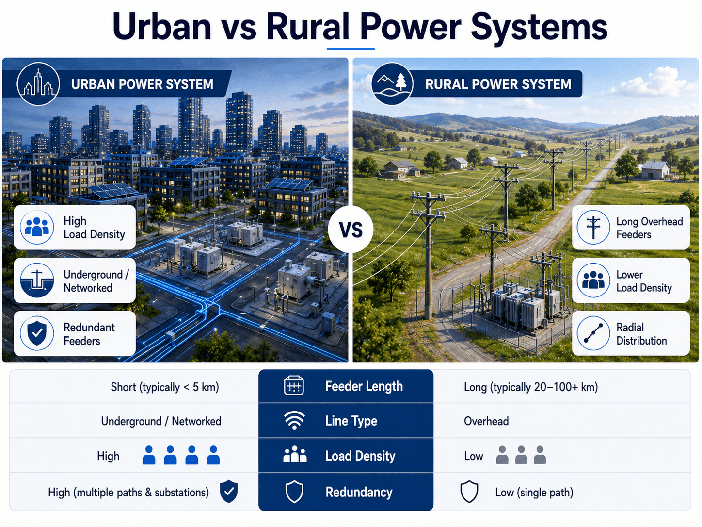
Urban and rural power systems use many of the same electrical principles, but they solve different problems. Urban systems deal with high demand in a small area, limited physical space, high outage consequences, and more complex coordination with buildings, streets, transit, telecom, and emergency infrastructure.
| Design feature | Urban power system | Rural power system |
|---|---|---|
| Load density | High loads are concentrated in buildings, districts, transit systems, and commercial centers. | Loads are spread across farms, small towns, remote homes, and long service territories. |
| Typical routing | More underground ducts, vaults, compact equipment, and networked routes in dense areas. | More overhead radial feeders and long pole-line routes. |
| Outage consequence | A small geographic outage can affect many customers or critical public services. | A long feeder outage may affect fewer customers but over a larger area. |
| Maintenance access | Access may require traffic control, vault entry, utility coordination, and limited work windows. | Access may require long travel distances, vegetation management, and weather exposure. |
What Controls Urban Power System Design?
The design of an urban power system is controlled by more than peak kilowatts. Engineers must consider where the load is located, how it changes during the day, what equipment can fit in the available space, how quickly faults can be isolated, and which customers must remain energized during abnormal conditions.
At the feeder and transformer level, a simple three-phase power relationship helps show why voltage level, current, and power factor matter:
- \(P\) Three-phase real power served by the feeder or transformer, typically expressed in watts, kilowatts, or megawatts.
- \(V\) Line-to-line voltage. Higher distribution voltage can move more power for a given current, but equipment insulation, safety, and utility standards control voltage selection.
- \(I\) Line current. Current affects conductor heating, cable ampacity, transformer loading, and protection settings.
- PF Power factor. Poor power factor increases current for the same useful real power and can reduce available capacity.
| Design control | Why it matters | Engineering implication |
|---|---|---|
| Load density | Dense buildings can concentrate large demand on a small number of transformers and feeders. | Substation spacing, feeder capacity, transformer sizing, and thermal monitoring become critical. |
| Underground cable thermal limits | Buried cables are limited by soil conditions, duct banks, cable spacing, and heat dissipation. | A cable may be physically intact but still overloaded if the thermal environment is poor. |
| Critical loads | Hospitals, water pumping, emergency communications, transit, and data centers have high outage consequences. | These loads may require redundant feeds, transfer schemes, backup generation, or microgrid planning. |
| Fault isolation | A cable fault or transformer failure should not interrupt a wider district than necessary. | Sectionalizing devices, relays, breakers, network protectors, and switching procedures must be coordinated. |
| DER and EV growth | Solar, batteries, and charging stations can change both demand and power-flow direction. | Hosting capacity, voltage regulation, protection settings, and visibility must be reviewed as adoption grows. |
Underground Distribution and Networked Feeders in Cities
Many cities use underground distribution because overhead routing is difficult in dense corridors. Underground cables reduce exposure to wind, trees, and visual conflicts, but they introduce different engineering problems: heat buildup, difficult inspection, fault location challenges, vault access, drainage, and longer repair times.
Urban feeders may also be looped or networked so power can be supplied from more than one path. This improves flexibility during maintenance or outages, but it also makes switching logic and protection coordination more important. A networked system needs clear operating boundaries so crews know which devices isolate a fault and which devices can safely backfeed a load.
Underground does not mean maintenance-free. Cable vaults can flood, duct banks can run hot, access may require street closures, and crews may need specialized fault-location equipment before repair work can even begin.
Reliability Metrics Used in Urban Power Systems
Urban grid reliability is usually measured with outage duration, outage frequency, and restoration performance. These metrics are useful because they turn reliability from a general goal into something engineers, utilities, regulators, and operators can track over time.
| Metric | What it measures | Why it matters in cities |
|---|---|---|
| SAIDI | Average outage duration per customer over a reporting period. | Shows how long customers are interrupted and whether restoration performance is improving. |
| SAIFI | Average outage frequency per customer over a reporting period. | Shows how often customers experience interruptions, even if each outage is short. |
| CAIDI | Average restoration time for customers who experienced an interruption. | Helps evaluate how quickly crews, automation, and switching procedures restore affected areas. |
| Momentary interruptions | Short-duration interruptions, recloser operations, or power quality events. | Important for elevators, controls, data equipment, healthcare loads, and sensitive building systems. |
A city can have strong average reliability but still have weak points around specific substations, underground routes, critical facilities, or fast-growing load pockets. That is why planners often look beyond systemwide averages and study feeder-level performance, contingency capacity, and restoration paths.
Smart Grid Controls, Visibility, and Restoration
Smart grid technology is valuable in urban power systems because operators need fast visibility. Sensors, smart meters, SCADA, distribution automation, fault indicators, and remote switching can help locate outages, estimate affected customers, reconfigure feeders, and restore service faster than manual patrol alone.
The important point is that smart grid equipment is not automatically a reliability improvement. It must be paired with correct protection settings, communications reliability, operator training, cybersecurity practices, and switching procedures. A sensor that reports bad data or a switch that cannot be operated during a communications failure can create false confidence.
- Outage detection: smart meters and feeder sensors help identify which parts of the network lost voltage.
- Automated switching: sectionalizing devices can isolate faulted sections and restore unfaulted sections through alternate paths.
- Voltage management: regulators, capacitor banks, inverters, and controls help keep voltage within acceptable ranges as load and DER output change.
- Asset loading: transformer and feeder monitoring can reveal overloads before they become failures.
In dense cities, utilities may also consider non-wires alternatives such as targeted energy efficiency, demand response, battery storage, or local generation when a traditional feeder or substation upgrade is expensive, slow, or difficult to site.
DERs, Storage, EV Charging, and Urban Microgrids
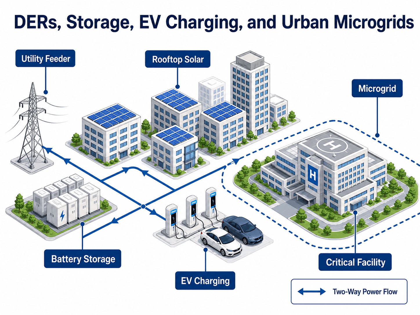
Modern urban power systems increasingly include distributed energy resources. Rooftop solar, battery storage, combined heat and power, EV charging, and building-level energy systems can reduce peak demand or support resilience, but they also make the distribution network more dynamic.
Hosting capacity is the amount of DER or load growth a feeder can accept before voltage, thermal loading, protection coordination, or power quality limits are violated. In urban areas, hosting capacity can vary block by block because transformers, secondary networks, and underground duct banks may have very different remaining capacity.
EV charging is one of the most important new urban loads because chargers can be clustered in parking garages, curbside corridors, fleets, apartments, and commercial districts. A transformer that was adequate for traditional building load may become overloaded when several high-power chargers are added without a coordinated load study.
Microgrids are a related but distinct concept. A microgrid is a local electrical system that can coordinate generation, storage, and loads within a defined boundary. In a city, a microgrid may support a hospital, university, transit facility, emergency shelter, water plant, or district energy campus when the main grid is disturbed.
Urban Power System Failure Mode Checklist
A useful way to understand urban power systems is to ask what can fail and how the system limits the impact. The table below works as a practical review checklist for students, engineers, and technical readers evaluating city-grid reliability.
Start with the load pocket, identify the normal supply path, identify alternate supply paths, check protection zones, review transformer and feeder loading, then ask how the system behaves if the most important cable, transformer, breaker, or communications link fails.
| Failure mode | What to look for | Why it matters in a city grid |
|---|---|---|
| Feeder overload | Rising current, voltage complaints, thermal alarms, or frequent load transfers during peaks. | Dense loads can consume spare capacity quickly, especially after redevelopment or EV charger installation. |
| Underground cable fault | Localized outage, fault indicators, protective relay operation, or failed insulation test results. | Fault location and excavation can take time, so sectionalizing and alternate feeds are essential. |
| Transformer overload | High loading during hot weather, elevated transformer temperature, or accelerated aging concerns. | One urban transformer may support many customers or a building with critical mechanical and life-safety loads. |
| Protection miscoordination | Too many customers trip offline for a localized fault, or a downstream fault does not isolate cleanly. | Dense networks need selective tripping so a small equipment fault does not become a district outage. |
| Poor DER visibility | Unexpected reverse power flow, voltage swings, or inverter behavior not reflected in operating models. | Behind-the-meter resources can change feeder behavior without being obvious from traditional load records. |
| Communications or automation failure | Remote switch unavailable, stale sensor values, or outage management data that does not match field conditions. | Automated restoration plans need manual fallback procedures when communications fail. |
Senior Engineer Review Checklist for Urban Grid Planning
A strong urban power system review does not stop at one-line diagrams or equipment ratings. It checks normal operation, contingency operation, field access, future load growth, and how the system behaves when automation or alternate paths are unavailable.
| Review item | Question to ask | Why it matters |
|---|---|---|
| Load forecast | Has redevelopment, electrification, EV charging, and seasonal peak demand been considered? | Historic load may understate future transformer and feeder demand in a fast-changing city district. |
| Feeder capacity | Can normal and contingency feeder paths carry the expected load? | Redundancy only helps if the alternate path has enough available capacity. |
| Transformer loading | Are transformers checked under hot weather, emergency transfer, and future load-growth conditions? | Transformer thermal aging can become the hidden limit in dense building areas. |
| Critical loads | Are hospitals, water systems, transit, telecom, emergency shelters, and data centers identified? | Not all customers have the same outage consequence or restoration priority. |
| Protection coordination | Do faults isolate selectively under normal, transfer, and possible DER backfeed conditions? | Incorrect settings can turn a local fault into a wider outage or leave equipment exposed. |
| DER visibility | Are solar, storage, controllable loads, and microgrid operating modes included in assumptions? | Hidden resources can change voltage, current, and fault behavior at the feeder level. |
| Restoration plan | Can crews isolate faults and restore unfaulted sections safely with realistic access? | Vault entry, traffic control, switching orders, and communications failures can control real restoration time. |
Engineering Judgment and Field Reality
Urban power system drawings can look clean, but field conditions are rarely simple. Equipment may be installed in constrained vaults, transformer rooms, rooftops, alleys, or sidewalk cabinets. A feeder route may share space with water, sewer, telecom, transportation, and building utilities. That means electrical design often depends on civil access, traffic control, ventilation, drainage, permitting, and maintenance logistics.
Load forecasting is another field reality. A city district can change quickly when offices convert to residential use, high-rise buildings add electrified heating, transit agencies add charging infrastructure, or commercial loads shift from daytime peaks to mixed-use evening peaks. Engineers should treat historic load as a starting point, not a guarantee of future capacity.
In dense urban areas, the limiting issue may be a duct bank, transformer vault, switching constraint, or outage restoration path rather than the theoretical capacity of a single conductor or transformer nameplate.
When This Breaks Down
Simplified urban power system diagrams break down when they imply that power always flows in one direction, that underground systems are automatically resilient, or that a city grid can be understood without protection, communication, access, and operational constraints.
- DER backfeed changes assumptions: solar, batteries, and microgrids can create power flow from the customer side back toward the feeder.
- Thermal limits are hidden: underground cables and transformer vaults may overheat even when the equipment is not visually damaged.
- Redundancy may not be usable: an alternate feeder only helps if it has spare capacity, correct switching equipment, and acceptable protection coordination.
- Diagrams hide protection zones: a clean one-line diagram may not show which relay, breaker, fuse, or network protector actually trips for a fault.
- Backup power is not the same as resilience: a generator may support one building, but it does not automatically provide feeder-level restoration, black-start coordination, load prioritization, or microgrid islanding.
- Critical-load planning is site-specific: a hospital, water plant, transit hub, and apartment tower do not have the same outage tolerance or restoration priority.
Urban Power System Misconceptions
Urban grid terminology can be confusing because the same city may include overhead lines, underground cables, radial feeders, looped feeders, secondary networks, backup generators, and microgrids. These misconceptions are common when the system is explained too simply.
| Misconception | Better engineering interpretation |
|---|---|
| Underground cables make the grid outage-proof. | Underground cables reduce some exposures, but faults can be harder to locate and repairs may require excavation or vault access. |
| Smart meters make the grid smart. | Smart meters improve visibility, but restoration still depends on switches, crews, controls, protection settings, and procedures. |
| EV charging is just another building load. | Clustered high-power charging can overload transformers, shift peak demand, and change feeder upgrade priorities. |
| Microgrids are just backup generators. | A true microgrid coordinates generation, storage, controls, islanding, reconnection, and load prioritization. |
| Redundant feeders always guarantee reliability. | Redundancy only helps when the alternate path has capacity, correct switching, and safe protection coordination. |
Common Mistakes and Practical Checks
The biggest mistakes usually come from treating an urban power system as a generic distribution network. City grids are shaped by density, access constraints, restoration priorities, and fast-changing load patterns.
- Assuming underground equals reliable: underground cables avoid many weather exposures but can be harder to inspect, access, and repair.
- Ignoring load growth: EV charging, building electrification, data rooms, and redevelopment can consume spare capacity faster than expected.
- Overlooking protection coordination: adding DERs, networked feeders, or new switchgear can change fault current and trip behavior.
- Confusing smart devices with smart operation: automation only improves reliability when communications, data validation, procedures, and operator training are in place.
Do not judge urban grid resilience from a single component. A city power system is only as reliable as its weakest combination of equipment capacity, switching flexibility, protection settings, access, and restoration planning.
Useful References and Design Context
Urban power system planning often draws from utility standards, interconnection requirements, distribution planning criteria, protection studies, and resilience guidance. A strong technical reference should help connect the physical distribution network with restoration planning, local resources, and grid resilience.
- U.S. Department of Energy: DOE guidance on resilient distribution systems explains how distribution systems can use local resources such as solar energy and storage to support resilience and recover service after disturbances.
- Project-specific criteria: Utility service rules, local interconnection procedures, protection requirements, and authority-having-jurisdiction requirements still control final design decisions.
- Engineering use: Engineers use these references to frame outage recovery, critical-load support, DER coordination, and distribution planning assumptions for real city networks.
Frequently Asked Questions
An urban power system is the electrical infrastructure that supplies and manages power for dense city environments. It includes substations, primary feeders, transformers, secondary networks, underground cables, protection equipment, monitoring systems, distributed energy resources, and controls that keep buildings, transit, hospitals, businesses, and public services energized.
Urban power systems usually serve higher load density over shorter distances, use more underground or networked distribution, and require more redundancy, automation, and outage coordination. Rural systems often use longer overhead radial feeders serving fewer customers spread across larger areas.
Cities use underground cables because space is limited, overhead lines can conflict with buildings and streetscapes, and underground routes are less exposed to wind, trees, and vehicle impacts. The tradeoff is higher installation cost, more difficult fault location, thermal constraints, and slower repair access.
Distributed energy resources, batteries, EV chargers, and microgrids change urban power systems from one-way delivery networks into more dynamic systems with local generation, storage, variable demand, and possible two-way power flow. Engineers must account for voltage regulation, protection coordination, visibility, and critical-load resilience.
Urban power system reliability depends on capacity, redundancy, selective fault isolation, protection coordination, restoration procedures, equipment access, monitoring, and spare capacity. Underground construction, smart meters, or backup generation can help, but none of them guarantee reliability by themselves.
Summary and Next Steps
Urban power systems are dense, layered electrical networks built to serve city loads where space is limited and outage consequences are high. They combine substations, feeders, transformers, underground distribution, protection devices, smart grid controls, DERs, storage, and microgrids into an operating system for modern cities.
The practical engineering challenge is balancing capacity, reliability, restoration speed, thermal limits, critical-load needs, DER growth, and future development. A good city grid is not just larger than a rural grid; it is more constrained, more interconnected, and more dependent on visibility, switching flexibility, and field access.
Where to go next
Continue your learning path with related Turn2Engineering resources.
-
Power Distribution
Learn how local distribution networks move electricity from substations to customers.
-
Smart Grids
Explore how monitoring, automation, and communication systems improve grid visibility and control.
-
Microgrids
See how local generation, storage, and controlled loads can support resilience for campuses, districts, and critical facilities.