
Key Takeaways
- Core idea: Wastewater treatment plant components are the physical, biological, chemical, solids-handling, and control systems that turn raw sewage into treated effluent and manageable biosolids.
- Engineering use: Engineers evaluate components as a connected treatment train, not as isolated tanks, because recycle flows and sludge handling can control the entire plant.
- What controls it: Component selection depends on influent flow, BOD, TSS, grit, nutrients, permit limits, discharge or reuse goals, land availability, energy cost, and operator capability.
- Practical check: A complete plant review traces liquid flow, solids flow, RAS, WAS, backwash waste, chemical feed, instrumentation, bypasses, redundancy, and maintenance access.
Table of Contents
Introduction
Wastewater treatment plant components are the connected units that receive raw wastewater, remove debris and grit, settle solids, biologically treat dissolved pollution, disinfect the final effluent, and process sludge into biosolids. The best way to understand a plant is to follow both the liquid stream and the solids stream, because recycle flows, sludge wasting, and side streams often control real performance.
Wastewater Treatment Plant Components Flow Diagram
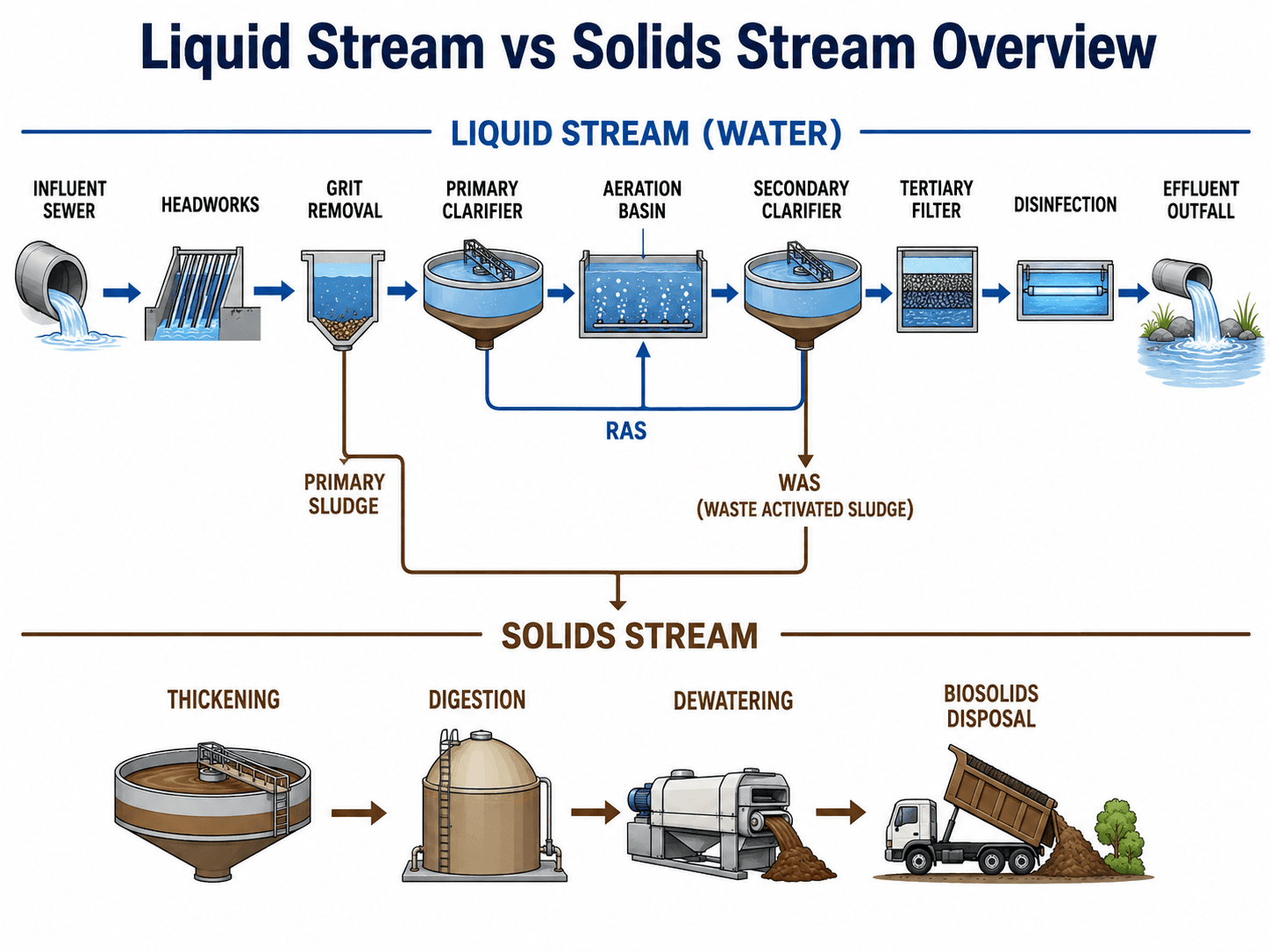
Start by tracing the blue liquid path from influent sewer to effluent outfall. Then trace the brown solids path from primary sludge and WAS to thickening, digestion, dewatering, and biosolids disposal.
What Are Wastewater Treatment Plant Components?
Wastewater treatment plant components are the individual structures, tanks, channels, pumps, mechanical equipment, chemical systems, sensors, and control systems that work together to treat sewage. Some components remove solids by physical separation, some support biological treatment, some disinfect treated water, and others process the sludge removed from the liquid stream.
The important engineering idea is that each component prepares wastewater for the next component. Screens protect pumps and basins. Grit removal protects mechanical equipment. Primary clarifiers reduce solids before biological treatment. Aeration basins remove dissolved and suspended organic matter. Secondary clarifiers separate biomass from treated water. Filters and disinfection systems polish the effluent before discharge or reuse.
| Component group | Main purpose | Typical components | What leaves this stage |
|---|---|---|---|
| Preliminary treatment | Protect downstream equipment and remove large or abrasive material. | Influent channel, screens, grit chamber, grit classifier, flow meter, odor control. | Screenings, grit, and screened wastewater. |
| Primary treatment | Remove settleable solids and floating scum before biological treatment. | Primary clarifier, scum skimmer, sludge scraper, primary sludge pumps. | Primary sludge, scum, and primary effluent. |
| Secondary treatment | Use microorganisms to remove organic matter and separate biomass from treated water. | Aeration basin, blowers, diffusers, secondary clarifier, RAS pumps, WAS pumps. | Clarified secondary effluent, RAS, and WAS. |
| Tertiary and final treatment | Polish effluent, remove remaining solids or nutrients, and reduce pathogens. | Filters, nutrient-removal zones, UV disinfection, chlorine contact basin, outfall. | Final effluent, backwash waste, and sometimes chemical residuals. |
| Solids handling | Thicken, stabilize, dewater, store, and dispose of removed solids. | Thickener, digester, centrifuge, belt press, screw press, biosolids storage. | Dewatered cake, biosolids, filtrate, centrate, or sidestream return. |
| Support systems | Keep the process measurable, controllable, safe, and reliable. | SCADA, laboratory sampling, chemical feed, standby power, pumps, alarms. | Control data, chemical dosing, alarms, records, and maintenance actions. |
A plant component is not defined only by what it removes. It should also be understood by its hydraulic role, solids output, maintenance needs, control points, failure modes, and relationship to upstream and downstream units.
How the Components Are Arranged in a Plant
A wastewater treatment plant layout is usually organized around gravity flow, maintenance access, odor control, safety, site constraints, and separation between clean, dirty, chemical, and solids-handling areas. Circular clarifiers, rectangular aeration basins, headworks buildings, blower rooms, digesters, and dewatering buildings are often easy to recognize from an aerial view.
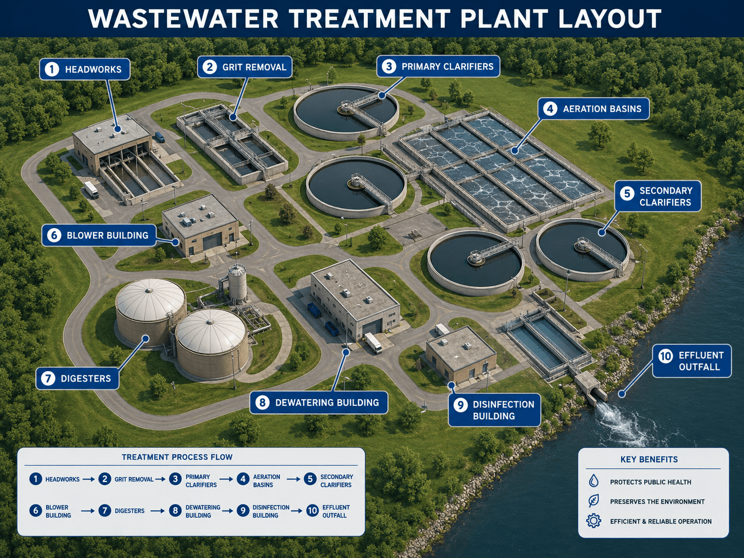
A simple flow diagram is useful for learning the process, but a plant layout adds the practical engineering layer: where equipment sits, how access roads work, where odors are generated, where trucks load biosolids, and how treated effluent reaches the receiving water or reuse system.
Preliminary Treatment Components
Preliminary treatment is the front end of a wastewater plant. Its purpose is not to remove dissolved pollution. Its purpose is to protect the rest of the facility from rags, wipes, plastics, sticks, sand, gravel, and other material that can damage pumps, plug pipes, reduce basin volume, or wear out mechanical equipment.
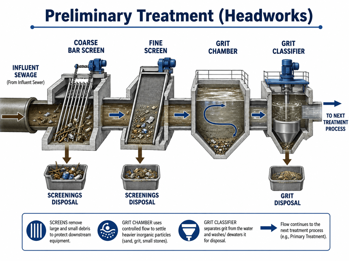
Influent sewer and headworks channel
The influent sewer or force main delivers wastewater from the collection system to the plant. The headworks channel may include gates, flow splitting, flow measurement, bypass structures, sampling points, and odor-control covers. Engineers look closely at hydraulic grade, peak wet-weather flow, grit deposition, and whether the channel can be isolated for maintenance.
Coarse screens and fine screens
Bar screens and fine screens remove large debris before it reaches pumps and basins. Coarse screens catch larger material such as rags, wipes, sticks, and plastics. Fine screens capture smaller debris and may reduce loading on downstream tanks. Screenings usually require washing, compacting, and disposal.
Grit removal and grit classification
Grit chambers slow or direct the flow so dense inorganic particles settle while lighter organic solids remain in the wastewater. A grit classifier or washer separates grit from water and removes excess organics before disposal. Poor grit removal can damage pumps, abrade valves, reduce tank capacity, and create maintenance problems throughout the plant.
Preliminary treatment should be reviewed at peak flow and low flow. A grit chamber that works at average flow may scour settled grit during storms or allow grit to accumulate during low-velocity periods.
Primary Treatment Components
Primary treatment removes solids that settle by gravity and materials that float to the surface. The main component is the primary clarifier, which reduces solids and organic load before secondary treatment. This helps the biological process operate more efficiently and reduces the amount of oxygen required downstream.
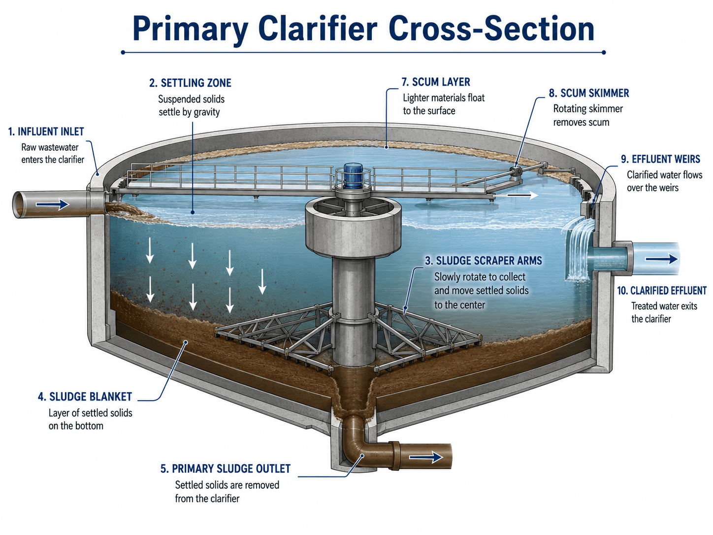
Primary clarifier
A primary clarifier may be circular or rectangular. Wastewater enters the tank, velocity drops, heavier solids settle to the bottom, scum floats to the surface, and clarified wastewater flows over effluent weirs. The settled solids become primary sludge and are pumped to solids handling.
Scum removal and sludge collection
Skimmers remove grease, oils, and floating material from the surface. Sludge scraper arms or chain-and-flight mechanisms move settled solids to a hopper. If sludge is not removed consistently, it can become septic, release gas, float, and carry solids into the secondary treatment process.
What controls primary treatment performance?
Primary clarifier performance depends on surface overflow rate, detention time, inlet energy, short-circuiting, sludge withdrawal frequency, scum handling, and whether industrial or wet-weather flows change the character of the influent.
Secondary Treatment Components
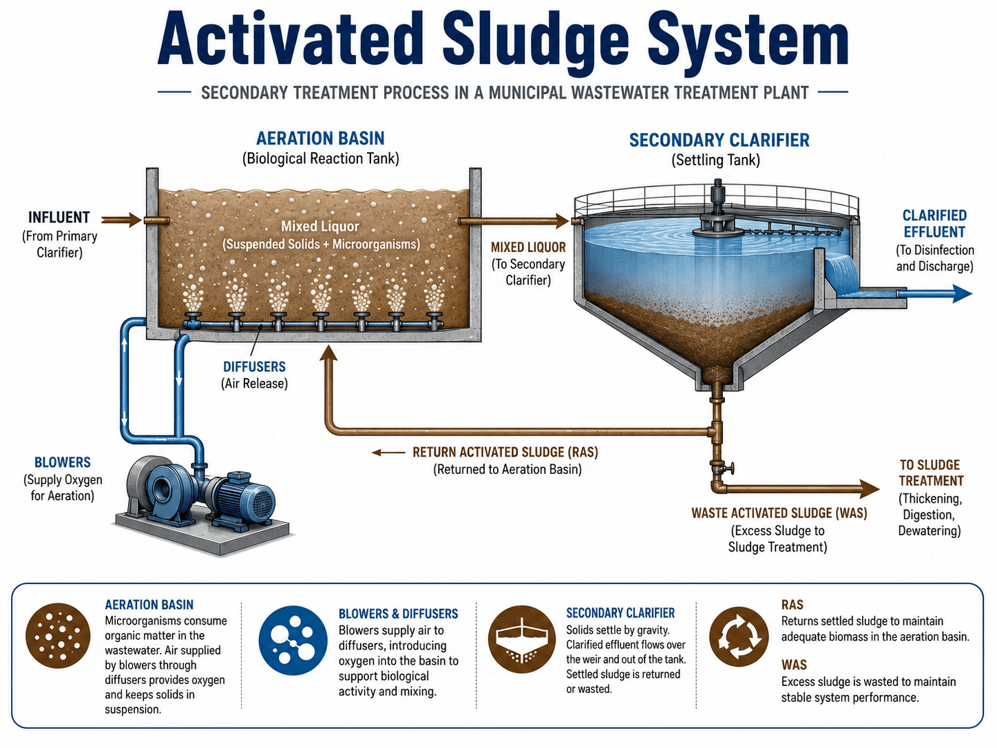
Secondary treatment is where most biological removal occurs. In a conventional activated sludge plant, the core components are the aeration basin, air supply system, secondary clarifier, return activated sludge system, and waste activated sludge system. Together, these components grow, mix, settle, return, and waste the microorganisms that perform treatment.
Aeration basin or biological reactor
The aeration basin holds mixed liquor, which is wastewater combined with suspended microorganisms. These microorganisms consume organic matter and, when conditions are right, convert ammonia to nitrate. The basin may include aerobic zones, anoxic zones, anaerobic zones, mixers, baffles, internal recycle pumps, and dissolved oxygen controls.
Blowers, air piping, and diffusers
Blowers supply air to diffusers at the bottom of the aeration basin. The air provides oxygen and mixing. Fine-bubble diffusers are efficient but can foul; coarse-bubble systems are often more robust but less efficient. Aeration is usually one of the largest energy uses in a wastewater treatment plant.
Secondary clarifier
The secondary clarifier separates biological solids from treated water. A well-settling sludge blanket allows clear effluent to flow over the weirs while settled biomass is pumped back to the aeration basin. Poor settling can cause solids washout, high effluent suspended solids, and disinfection problems.
RAS and WAS systems
Return activated sludge, or RAS, keeps enough biomass in the aeration basin. Waste activated sludge, or WAS, removes excess biomass from the system. Operators adjust RAS and WAS to control solids concentration, sludge age, settling behavior, oxygen demand, and biological process stability.
Nutrient Removal Components
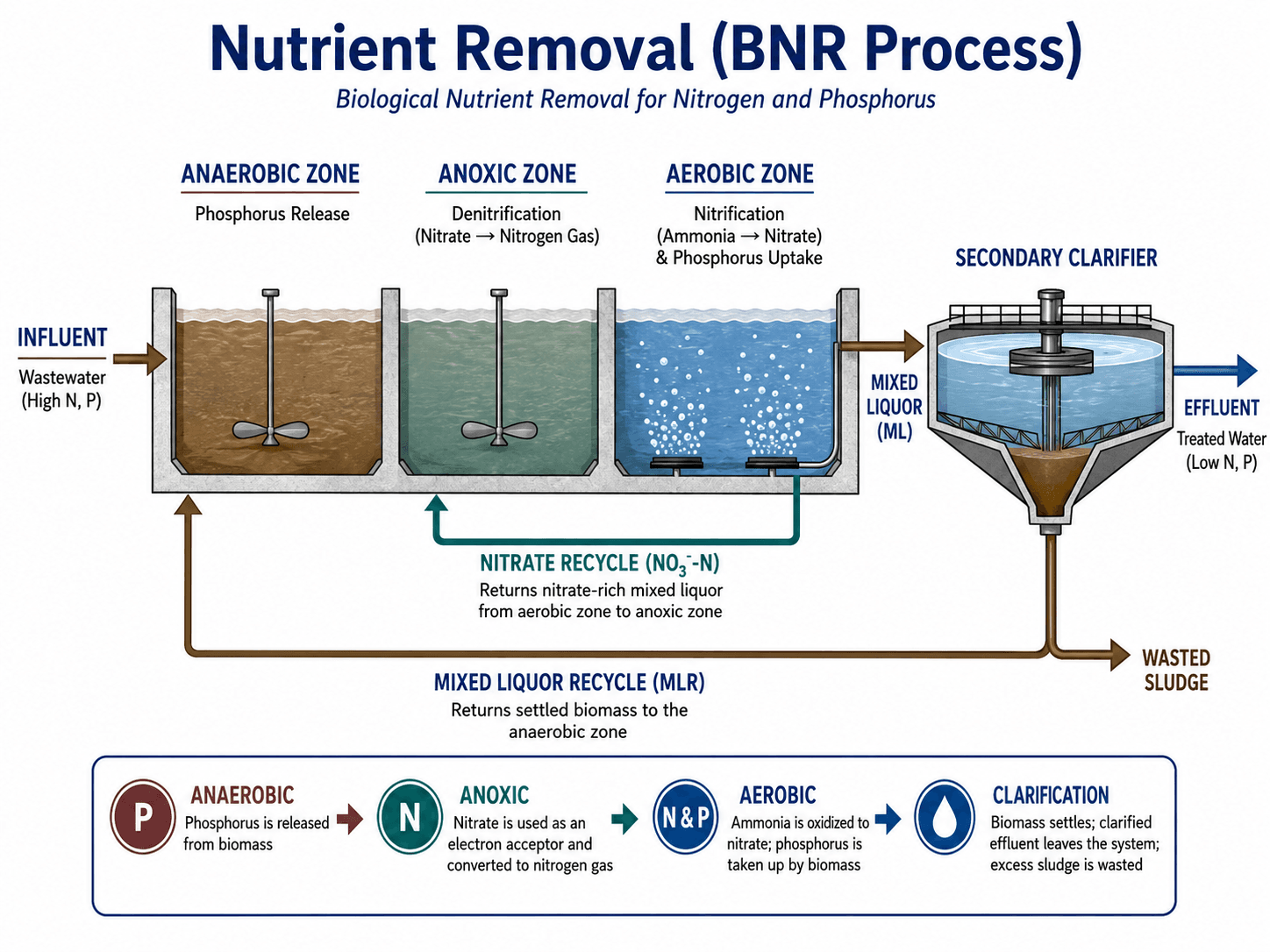
Many modern wastewater plants must remove nitrogen and phosphorus in addition to BOD and suspended solids. Nutrient-removal components may be built into the biological reactor, added as chemical feed systems, or combined with tertiary polishing. These systems are especially important when treated effluent discharges to nutrient-sensitive rivers, lakes, estuaries, or reuse systems.
Anaerobic, anoxic, and aerobic zones
Anaerobic zones support biological phosphorus release and later uptake. Anoxic zones allow denitrification, where nitrate is converted to nitrogen gas. Aerobic zones support BOD removal, nitrification, and phosphorus uptake. These zones only work properly when recycle flows, mixing, dissolved oxygen, and carbon availability are controlled.
Internal recycle and chemical feed
Internal mixed liquor recycle moves nitrate-rich flow from the aerobic zone back to the anoxic zone. Chemical feed systems may add alum, ferric salts, polymer, carbon source, alkalinity, or pH adjustment chemicals depending on the plant’s permit and process design.
Nutrient removal often fails because the biology is asked to do something the upstream hydraulics or chemistry will not support. Low alkalinity, low carbon, excessive dissolved oxygen carryover, poor recycle control, and variable industrial loading can all limit performance.
Tertiary Filtration, Disinfection, and Effluent Components
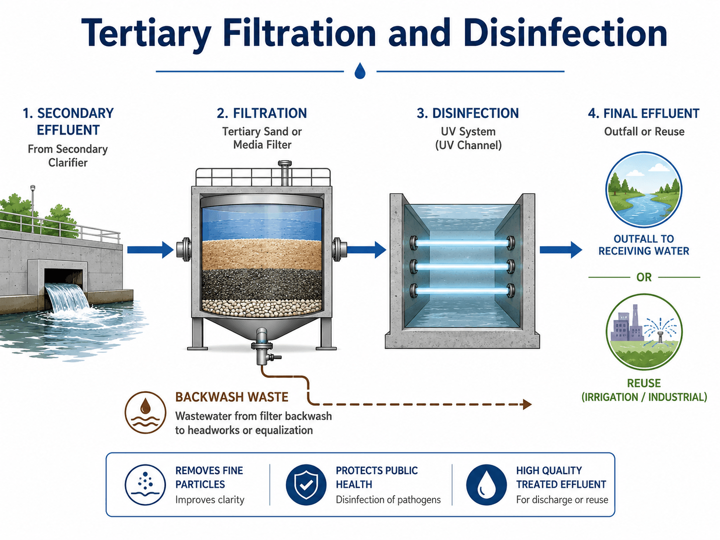
Tertiary and final-treatment components polish the secondary effluent before discharge or reuse. Not every facility has the same tertiary process, but filters, disinfection systems, effluent monitoring, and outfalls are common when high-quality effluent is required.
Tertiary filters
Tertiary filters may include sand filters, cloth media filters, disk filters, granular media filters, or membranes. Their role is to remove remaining suspended solids, improve clarity, and support downstream disinfection or reuse requirements. Backwash waste is commonly returned to the head of the plant or another suitable process point.
Disinfection systems
Disinfection reduces pathogens before treated effluent leaves the plant. Common systems include ultraviolet disinfection, chlorine contact basins, and dechlorination systems where chlorine residual must be removed before discharge. The selected system depends on flow range, turbidity, permit requirements, contact time, maintenance capacity, and safety considerations.
Effluent monitoring and outfall
The final effluent channel or outfall may include flow measurement, sampling, residual monitoring, turbidity monitoring, and access for compliance testing. The outfall must safely discharge treated water to a receiving stream, river, lake, reuse distribution system, or other permitted endpoint.
Sludge and Biosolids Handling Components
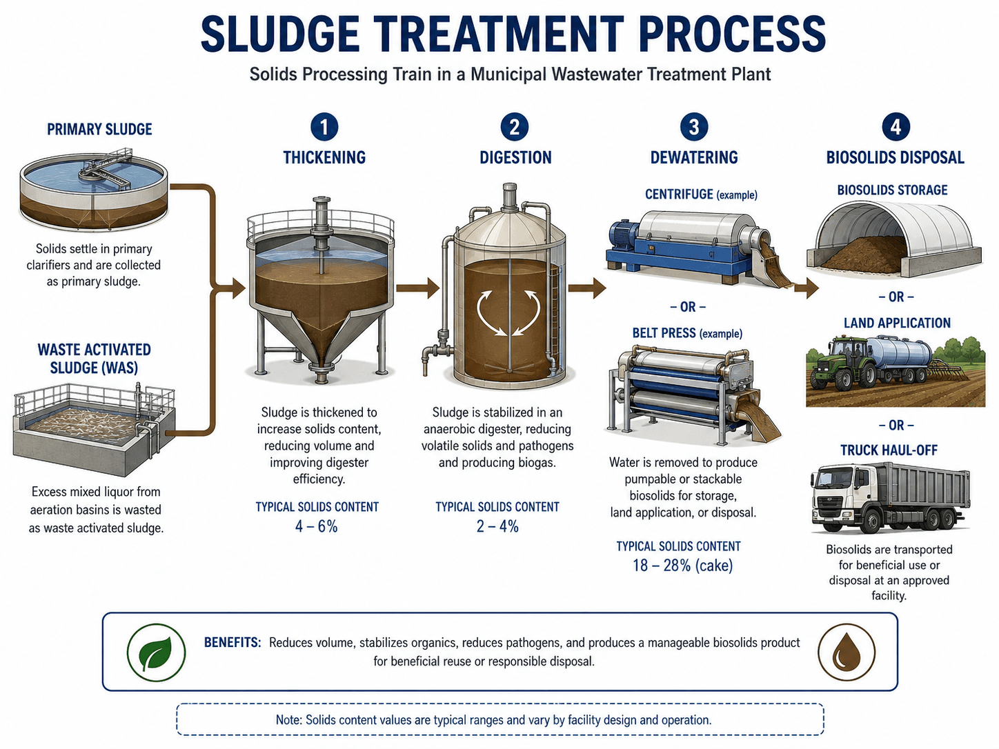
The solids train is a major part of a wastewater treatment plant. Primary sludge, waste activated sludge, scum, and other residuals must be thickened, stabilized, dewatered, stored, hauled, reused, or disposed of. A plant can meet liquid-treatment goals and still struggle if the sludge system becomes the bottleneck.
Sludge thickening
Thickening increases solids concentration before digestion or dewatering. Common equipment includes gravity thickeners, dissolved air flotation thickeners, rotary drum thickeners, and gravity belt thickeners. Thickening reduces downstream tank volume, heating load, polymer use, and hauling demand.
Digestion
Digesters stabilize sludge by reducing volatile solids, odors, and pathogen potential. Anaerobic digesters can produce biogas for heat or power. Aerobic digesters are often simpler but may require more energy. Digester performance depends on temperature, mixing, solids loading, retention time, alkalinity, and process stability.
Dewatering and biosolids management
Dewatering equipment removes water from sludge to produce a cake that can be stored, hauled, land-applied, composted, or disposed of. Common equipment includes centrifuges, belt filter presses, screw presses, and polymer feed systems. Poor dewatering can drive up hauling costs and create storage or odor issues.
Support Systems That Keep the Plant Working
Support systems are easy to overlook because they are not always shown in simple treatment diagrams. In real operations, pumps, instrumentation, chemical feed systems, standby power, odor control, and laboratory sampling often determine whether the visible process tanks perform as intended.
| Support component | What it does | Why it matters |
|---|---|---|
| Pump stations | Move influent, intermediate flow, return sludge, waste sludge, scum, backwash, and effluent. | Pump failures can stop flow, flood channels, starve treatment units, or overload backup systems. |
| Chemical feed systems | Add disinfectants, coagulants, polymer, alkalinity, carbon source, or pH adjustment chemicals. | Wrong dosing can cause poor settling, disinfection failure, nutrient-limit violations, or excess residuals. |
| SCADA and instrumentation | Monitor flow, levels, dissolved oxygen, pH, ORP, turbidity, ammonia, nitrate, and alarms. | Operators need reliable data to control process performance, respond to alarms, and document compliance. |
| Odor control | Captures and treats odorous air from headworks, sludge handling, and enclosed process areas. | Odor problems often indicate septicity, poor ventilation, or sludge-handling issues and can affect nearby communities. |
| Laboratory and sampling | Measures influent, process, sludge, and effluent quality. | Sampling confirms whether the plant is actually meeting treatment objectives and permit requirements. |
| Standby power and alarms | Support critical equipment during outages or abnormal conditions. | Wastewater plants must remain functional during storms, power interruptions, and emergency events. |
When reviewing a wastewater treatment plant layout, do not stop at the tanks. Check whether the pumps, chemical systems, controls, bypasses, sampling points, maintenance access, and residuals handling are sized and arranged to support the process.
Common Wastewater Plant Configurations
Not every wastewater treatment plant uses the same component arrangement. The same treatment goals can be met using different process configurations, and each configuration changes which components are most important for performance, maintenance, energy use, and operator control.
| Plant configuration | Typical components | Best fit | Component-level tradeoff |
|---|---|---|---|
| Conventional activated sludge | Headworks, primary clarifiers, aeration basins, secondary clarifiers, RAS/WAS, disinfection, sludge handling. | Municipal plants with steady loading and space for separate process units. | Clear process separation but more tanks, pumps, and sludge-control points. |
| Oxidation ditch | Looped aeration channel, rotors or aerators, secondary clarification, RAS/WAS, disinfection. | Small to mid-sized plants needing robust biological treatment. | Operationally stable but can require significant land and aeration energy. |
| Sequencing batch reactor | Batch reactor tanks, decanters, aeration, controls, sludge wasting, disinfection. | Sites where treatment steps can occur in timed cycles within the same basin. | Compact layout but more dependent on controls, valves, decanters, and cycle timing. |
| Membrane bioreactor | Biological reactor, membrane modules, blowers, pumps, chemical cleaning, disinfection or reuse systems. | High-quality effluent, reuse applications, or space-limited sites. | Excellent solids separation but higher energy, membrane maintenance, and cleaning complexity. |
| Lagoon or pond system | Screening, ponds or lagoons, polishing, disinfection, sludge accumulation management. | Smaller communities with available land and simpler operation needs. | Lower mechanical complexity but larger land area and stronger climate sensitivity. |
How Engineers Think About Component Selection
Wastewater treatment plant components are selected as a system, not as isolated pieces of equipment. A component that performs well in one plant may be a poor choice in another because flow variation, nutrient limits, land availability, operator staffing, industrial waste strength, climate, and residuals handling are different.
| Design question | Component decision affected | Practical engineering implication |
|---|---|---|
| How variable is the influent flow? | Equalization, headworks hydraulics, clarifier sizing, pump capacity. | High peak flow can wash solids through clarifiers and reduce disinfection contact time. |
| Is nutrient removal required? | Anoxic zones, anaerobic zones, internal recycle, chemical feed, tertiary filters. | Nitrogen and phosphorus limits may change the entire biological reactor layout. |
| How much land is available? | Oxidation ditch, conventional activated sludge, MBR, SBR, lagoon, clarifier layout. | Compact processes can save land but may increase energy, controls, and maintenance complexity. |
| What is the solids-handling strategy? | Thickening, digestion, dewatering, storage, hauling, odor control. | Solids handling can become the controlling cost and operating constraint. |
| What level of operator support is available? | Automation, instrumentation, process complexity, redundancy, equipment selection. | A highly automated or nutrient-sensitive plant may need stronger monitoring and maintenance resources. |
Wastewater Plant Component Review Checklist
Use this checklist as a practical review tool when studying, sketching, or evaluating a wastewater treatment plant. The goal is to confirm that every major component has a clear purpose, a known flow path, a residuals path, a control point, and a failure response.
Trace the plant in this order: influent flow path, preliminary removal, primary settling, biological treatment, secondary clarification, recycle flows, tertiary polishing, disinfection, effluent monitoring, sludge handling, chemical systems, instrumentation, standby power, and maintenance access.
| Check or decision | What to look for | Why it matters |
|---|---|---|
| Trace the liquid stream | Confirm each tank, channel, filter, and disinfection unit has a clear upstream and downstream connection. | This catches missing bypasses, poor hydraulic logic, and process gaps. |
| Trace the solids stream | Identify where primary sludge, WAS, scum, grit, screenings, and backwash waste go. | Residuals handling often controls operating cost, odor, and reliability. |
| Check recycle flows | Locate RAS, WAS, nitrate recycle, backwash recycle, filtrate return, and centrate return. | Recycle loads can overload the head of plant or disrupt biological treatment. |
| Review hydraulic bottlenecks | Look at peak flow through screens, channels, clarifiers, filters, and disinfection contact volume. | A plant can fail during storms even if it works well at average flow. |
| Review maintenance access | Check isolation gates, bypass channels, cranes, hatches, walkways, and equipment removal paths. | Components that cannot be safely maintained often become long-term reliability problems. |
| Review instrumentation | Confirm flow, level, dissolved oxygen, pH, turbidity, nutrient, and alarm points match the process-control needs. | Operators cannot control what they cannot reliably measure. |
Component Failure Modes and What They Affect
A #1-level component guide should explain what can go wrong. Wastewater treatment plant components fail in connected ways: one weak link can affect hydraulics, solids capture, biological stability, disinfection, odor, safety, and permit performance.
| Component | Common failure mode | Downstream effect | Practical check |
|---|---|---|---|
| Screens | Blinding, bypassing, rake failure, screenings buildup. | Rags and debris reach pumps, valves, clarifiers, or aeration basins. | Check headloss, bypass evidence, screenings volume, and mechanical operation. |
| Grit chamber | Scouring at high flow or deposition at low flow. | Grit accumulates in channels, basins, pumps, digesters, and sludge equipment. | Review velocity range, grit washer performance, and grit accumulation points. |
| Primary clarifier | Short-circuiting, septic sludge, poor scum removal, high sludge blanket. | Excess solids and organic load reach biological treatment. | Check sludge withdrawal, scum skimming, weir loading, and odor conditions. |
| Aeration basin | Low dissolved oxygen, diffuser fouling, poor mixing, toxic loading. | Incomplete BOD removal, nitrification failure, odors, or poor settling. | Review DO profile, blower output, diffuser condition, MLSS, and process trends. |
| Secondary clarifier | Bulking sludge, rising sludge, high blanket, hydraulic overload. | Solids washout, cloudy effluent, filter overload, and disinfection problems. | Check sludge volume index, blanket depth, RAS rate, and surface overflow rate. |
| Filters | Short filter runs, breakthrough, poor backwash, media fouling. | High turbidity and reduced disinfection reliability. | Review headloss trends, turbidity, backwash rate, and media condition. |
| Disinfection | Low UV intensity, poor chlorine contact time, high solids, failed residual control. | Pathogen reduction may not meet permit or reuse requirements. | Check dose, contact time, turbidity, lamp condition, residual, and flow distribution. |
| Dewatering | Poor polymer dose, low cake solids, centrifuge or press upset. | Higher hauling costs, wet biosolids, odor, and storage issues. | Review feed solids, polymer use, cake solids, centrate/filtrate quality, and equipment condition. |
Engineering Judgment and Field Reality
Simplified wastewater diagrams usually show a clean linear process, but real plants are full of feedback loops, side streams, isolation gates, standby equipment, seasonal loading changes, and maintenance constraints. Engineers and operators must think about how the plant behaves during peak wet-weather flow, low-flow septic conditions, equipment outages, sludge hauling delays, diffuser fouling, and process upsets.
The most important component is not always the largest tank. A small chemical feed pump, plugged screen, failed dissolved oxygen probe, overloaded sludge thickener, or poorly controlled RAS pump can determine whether the entire facility performs well.
Wastewater treatment performance depends on flow path discipline. If a recycle stream, bypass line, or sludge return is misunderstood, the plant may appear properly designed on paper while operating as a very different process in the field.
When This Breaks Down
A component-level explanation breaks down when it treats each unit as independent. Wastewater plants fail as connected systems. A change at the headworks can affect clarifier loading, biological oxygen demand, sludge production, filter run time, disinfection performance, and biosolids handling.
- Wet-weather surcharging: High inflow and infiltration can overwhelm screens, clarifiers, filters, and disinfection contact time.
- Solids carryover: Poor settling in a clarifier can overload filters, reduce UV effectiveness, and increase effluent suspended solids.
- Side-stream loading: Centrate, filtrate, or backwash returns can add ammonia, solids, or organic load back to the head of the plant.
- Instrumentation drift: Faulty dissolved oxygen, pH, turbidity, or nutrient probes can drive incorrect control decisions.
- Deferred maintenance: Screens, scrapers, blowers, diffusers, pumps, valves, and polymer systems can quietly degrade until process performance collapses.
Common Mistakes and Practical Checks
The biggest mistakes come from confusing treatment stages with physical components, ignoring the solids train, or assuming every plant uses the same layout. A strong component review connects each structure to the pollutant it controls, the flow it receives, the residual it produces, and the operating decision it requires.
- Confusing primary and secondary clarifiers: Primary clarifiers remove raw settleable solids; secondary clarifiers separate biological solids after aeration.
- Ignoring RAS and WAS: The activated sludge process cannot be understood without the return and wasting loops.
- Forgetting sludge handling: Treatment does not end when water leaves the clarifier; removed solids still require stabilization and disposal.
- Treating disinfection as a cure-all: Disinfection works better when upstream solids and turbidity are controlled.
- Assuming every plant has tertiary treatment: Tertiary filtration, membranes, and advanced nutrient removal depend on permit limits and reuse goals.
Do not describe a wastewater plant only as screening, settling, aeration, and disinfection. A complete component-level explanation must include recycle flows, RAS, WAS, sludge handling, support systems, monitoring, and operational failure points.
Engineering References and Design Guidance
Wastewater treatment plant components should be understood through both process fundamentals and project-specific requirements. Public technical references are useful for learning the treatment train, but final component design depends on permits, local criteria, hydraulic design, equipment selection, and site-specific operating requirements.
- U.S. EPA wastewater treatment primer: EPA Primer for Municipal Wastewater Treatment Systems explains municipal wastewater treatment stages, treatment objectives, and system-level context for public wastewater facilities.
- Project-specific criteria: Local discharge permits, owner standards, state environmental requirements, reliability class, wet-weather design flow, and reuse objectives can all change the required component layout.
- Engineering use: Engineers use references, permits, design manuals, equipment data, pilot testing, and operator input together when selecting screens, clarifiers, aeration systems, filters, disinfection systems, sludge equipment, and instrumentation.
Frequently Asked Questions
The main components include the influent sewer, headworks, screens, grit removal system, primary clarifiers, aeration basins or biological reactors, secondary clarifiers, tertiary filters, disinfection systems, effluent outfall, sludge thickeners, digesters, dewatering equipment, pumps, chemical feed systems, odor control, instrumentation, and sampling systems.
Primary treatment components remove settleable solids and floating scum using physical separation, usually in a primary clarifier. Secondary treatment components use biological activity, aeration, and secondary clarification to remove dissolved and suspended organic matter that primary treatment cannot remove effectively.
Return activated sludge, or RAS, sends settled biological solids back to the aeration basin to maintain enough microorganisms for treatment. Waste activated sludge, or WAS, removes excess biomass from the system so solids age, settling, oxygen demand, and biological process stability can be controlled.
No. Most municipal plants have some form of preliminary treatment, biological treatment, clarification, disinfection, and solids handling, but the exact components vary by flow, permit limits, land availability, climate, industrial contribution, nutrient requirements, reuse goals, and operator resources.
Sludge-handling components may include primary sludge pumps, waste activated sludge pumps, gravity thickeners, dissolved air flotation thickeners, anaerobic or aerobic digesters, polymer feed systems, centrifuges, belt filter presses, screw presses, biosolids storage areas, and truck loading systems.
Summary and Next Steps
Wastewater treatment plant components are the connected systems that move raw wastewater from influent collection to treated effluent while separating, stabilizing, and managing solids. The major groups include preliminary treatment, primary clarification, biological treatment, secondary clarification, tertiary polishing, disinfection, solids handling, and plant-wide support systems.
The best way to understand a plant is to trace both the liquid stream and the solids stream. Then review recycle flows, pumps, chemical systems, instrumentation, maintenance access, and failure modes because those details often determine real-world performance.
Where to go next
Continue your learning path with related Turn2Engineering resources.
-
Wastewater Treatment Plants
Step back to the broader treatment-plant overview and see how the stages fit together.
-
How Wastewater Treatment Plants Work
Follow the full process from raw wastewater entering the plant to treated effluent leaving the facility.
-
Biological Treatment
Learn how microorganisms remove organic matter and nutrients in secondary and advanced treatment systems.