Key Takeaways
- Core idea: Cable-stayed structures use inclined tension cables connected directly to pylons to support a deck, roof, or long-span structural element.
- Engineering use: They are common in medium- and long-span bridges because they create an efficient load path using cable tension, pylon compression, and deck stiffness.
- What controls it: Cable layout, pylon height, deck stiffness, anchorage detailing, wind response, fatigue, corrosion protection, and construction sequence all influence performance.
- Practical check: A cable-stayed system should be reviewed as a staged, highly interactive structure—not as separate cables simply “holding up” a deck.
Table of Contents
Introduction
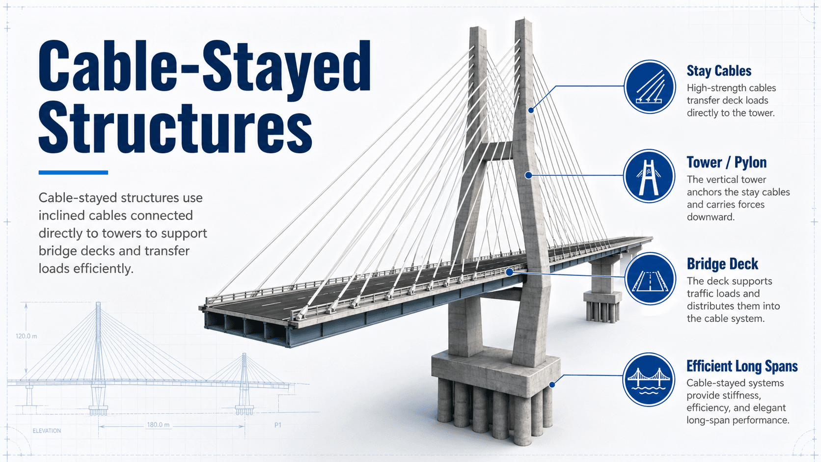
Cable-stayed structures are long-span systems where inclined tension cables connect a deck, roof, or other spanning element directly to one or more pylons. Loads move from the supported element into the stay cables, then into the pylons and foundations. The system is efficient because steel cables work well in tension while pylons carry large compression forces.
How Cable-Stayed Structures Work
Notice that each cable connects directly to the deck and pylon. That is the defining difference between a cable-stayed structure and a suspension system, where the deck hangs from vertical suspenders attached to a main cable.
What is a Cable-Stayed Structure?
A cable-stayed structure is a structural system that uses straight or nearly straight stay cables to support a spanning element from one or more pylons. In bridge engineering, the spanning element is usually a deck or girder. In other structures, the same idea can support roofs, canopies, pedestrian bridges, observation platforms, or specialty long-span systems.
The key engineering idea is not just the visual appearance of the cables. It is the force distribution. Stay cables carry tension, pylons carry compression and bending, the deck carries bending and axial force, and the foundations resist the combined vertical and horizontal effects. A cable-stayed structure is therefore a complete load-resisting system, not a collection of independent cables.
Load Path in a Cable-Stayed System
The load path begins at the deck. Dead load, live load, wind, temperature effects, seismic effects, and construction loads create demand in the deck. The inclined stay cables provide upward support, but because the cables are angled, each cable also introduces horizontal force into the deck and pylon.
Stay cable tension
A stay cable carries force primarily in tension. The vertical component of cable tension helps support the deck, while the horizontal component pushes or pulls on the deck and pylon. This is why deck stiffness and pylon stiffness matter: the whole system adjusts as cable forces change.
- T Stay cable tension, usually expressed in kips or kN.
- V Vertical component of cable tension that helps support the deck.
- H Horizontal component of cable tension that influences deck compression, pylon force, and anchorage demand.
- θ Cable angle measured relative to the deck or horizontal reference line.
Pylon compression and deck interaction
The pylon collects the forces from multiple stay cables and transfers them into the foundation. The deck is not passive; it usually participates as a stiffening element that resists bending and axial compression while helping balance the horizontal components from the cable system.
Main Components of Cable-Stayed Structures
A cable-stayed structure looks simple from a distance, but each component has a specific job. The efficiency of the system depends on how well the cables, pylons, deck, anchorages, and foundations work together.
- Stay cables: High-strength tension members that support the deck or roof and transfer force into the pylons.
- Pylons or towers: Vertical, inclined, A-shaped, H-shaped, or diamond-shaped members that collect cable forces and deliver them to the foundation.
- Deck or girder: The supported element that carries traffic, pedestrians, utilities, or roof loads while resisting bending, torsion, and axial effects.
- Anchorages: Critical connection zones where cable forces enter the deck and pylon.
- Foundations: Substructure elements that resist vertical reactions, overturning, lateral force, and foundation settlement effects.
- Dampers and protection systems: Components used to control cable vibration, fatigue, moisture intrusion, corrosion, and long-term durability.
When reviewing a cable-stayed structure, trace each cable force into the pylon, through the deck anchorage, and down into the foundation. Weakness often appears at connection zones, not in the middle of the cable.
Cable Arrangements: Fan, Harp, and Semi-Fan Systems
Cable arrangement affects cable force, deck bending, pylon detailing, appearance, constructability, and maintenance access. The three common layouts are fan, harp, and semi-fan systems.
| Cable arrangement | How it works | Engineering tradeoff |
|---|---|---|
| Fan | Cables converge near the top of the pylon, creating efficient cable angles. | Often efficient structurally, but pylon anchorage zones can become crowded and difficult to detail. |
| Harp | Cables are nearly parallel and spaced along the pylon height. | Visually clean and easier to space, but flatter lower cables may increase cable force and deck bending. |
| Semi-fan | Cables spread over the upper pylon rather than meeting at one point. | Often used as a practical compromise between structural efficiency, appearance, and constructability. |
The best cable layout depends on span length, pylon height, deck stiffness, aerodynamic behavior, construction method, and architectural goals. A layout that looks elegant may still create challenging anchorages or unfavorable cable force distribution.
Cable-Stayed Bridge vs. Suspension Bridge
Many readers confuse cable-stayed bridges with suspension bridges because both use cables and towers. The difference is the support system. Cable-stayed bridges use direct diagonal stays from pylon to deck. Suspension bridges use a main cable draped over towers, with vertical suspenders carrying the deck.
| Feature | Cable-stayed structure | Suspension structure |
|---|---|---|
| Main support system | Inclined stay cables connect directly from pylon to deck. | A main cable spans over towers and supports vertical suspenders. |
| Load path | Deck load enters individual stays, then pylons and foundations. | Deck load enters suspenders, then the main cable, towers, and anchorages. |
| Anchorages | Often less dependent on massive end anchorages. | Typically requires large anchorages for main cable tension. |
| Typical use | Efficient for many medium- and long-span crossings. | Often favored for very long spans where a continuous main cable is advantageous. |
| Common design focus | Cable force tuning, pylon stiffness, deck stiffness, stay vibration, and construction staging. | Main cable geometry, anchorage design, aerodynamic stability, and deck stiffening. |
What Controls the Design?
Cable-stayed structures are controlled by more than strength. Serviceability, stiffness, vibration, fatigue, construction sequence, and durability can be just as important as member capacity. A design that is strong enough may still perform poorly if cable forces are not tuned or if vibration and corrosion are not addressed.
| Design factor | Why it matters | Engineering implication |
|---|---|---|
| Span length | Longer spans increase gravity, wind, deflection, and dynamic demands. | Controls cable layout, pylon height, deck stiffness, and erection method. |
| Cable angle | Steeper cables provide more vertical support for a given tension. | Influences pylon height, cable force, deck compression, and anchorage demand. |
| Deck stiffness | The deck distributes loads and controls deflection, rotation, and torsion. | A flexible deck may need closer cable spacing, deeper girders, or different cable tuning. |
| Pylon stiffness | The pylon collects many cable forces and resists compression, bending, and lateral effects. | Pylon movement changes cable forces and deck geometry. |
| Wind response | Long cables and slender decks can be sensitive to wind and rain-wind vibration. | May require aerodynamic shaping, dampers, surface treatments, or wind-tunnel evaluation. |
| Durability | Stay cables, anchorages, and sheathing are exposed to long-term environmental attack. | Requires corrosion protection, inspection access, replaceability planning, and maintenance strategy. |
Construction Sequence and Cable Tuning
Cable-stayed bridges are commonly built using balanced cantilever construction. Deck segments are added outward from a pylon, and stay cables are installed and stressed as construction advances. Each new segment changes the force state of the partly completed structure.
Why construction stages matter
The final bridge may be stable and well balanced, but the incomplete bridge can experience temporary unbalanced moments, pylon deflection, deck rotation, and geometry errors. Engineers therefore analyze the structure in stages, not only in its final configuration.
What cable tuning does
Cable tuning adjusts stay forces so the deck profile, pylon position, internal forces, and long-term geometry remain within acceptable limits. The target is not simply equal cable force. The target is a force pattern that works with the deck, pylon, foundation, construction method, and service load behavior.
Geometry control is a construction issue and a design issue. Small cable force errors can accumulate into deck profile problems, pylon alignment issues, or unexpected locked-in forces.
Senior Engineer Review Checklist
A practical review of a cable-stayed structure should move from global behavior to local details. The checklist below is not a substitute for project design criteria, but it shows the types of questions experienced engineers use to avoid treating the structure as an idealized diagram.
Start with the span layout and support conditions. Trace the load path through cables, pylons, deck, anchorages, and foundations. Then check construction stages, serviceability, wind response, fatigue, durability, inspection access, and cable replacement assumptions.
| Check or decision | What to look for | Why it matters |
|---|---|---|
| Load path continuity | Clear transfer from deck loads into stay cables, pylons, anchorages, foundations, and soil or rock. | Discontinuous or poorly detailed load paths create stress concentrations and difficult-to-inspect weak points. |
| Cable force pattern | Reasonable force distribution across stays under dead, live, wind, thermal, and construction loads. | Uneven or poorly tuned cable forces can increase deck bending, pylon movement, and fatigue demand. |
| Deck and pylon stiffness | Deflection, rotation, drift, torsion, and vibration response under service loads. | Serviceability often controls long-span systems before strength becomes the governing issue. |
| Stay cable vibration | Long, lightly damped cables exposed to wind, rain-wind effects, or traffic-induced excitation. | Vibration can accelerate fatigue, damage protection systems, and reduce user confidence. |
| Anchorage detailing | Force transfer, fatigue detailing, corrosion protection, inspection access, and replaceability. | Anchorages are critical because they concentrate large cable forces into relatively compact regions. |
| Construction-stage stability | Temporary unbalanced cantilevers, erection equipment, cable stressing sequence, and geometry control. | The most demanding condition may occur before the final bridge is complete. |
Engineering Judgment and Field Reality
The simplified explanation of a cable-stayed structure says that cables hold the deck and pylons carry the force downward. That is useful for learning, but real projects are more interactive. Temperature changes, creep, shrinkage, bearing movements, cable replacement, deck resurfacing, wind response, and foundation movement can all change the force balance over time.
Field performance also depends on details that are easy to overlook in a concept sketch. Cable sheathing, water tightness, anchorage drainage, inspection ports, damper condition, fatigue detailing, and access for future maintenance all influence whether the structure remains serviceable for decades.
A beautiful cable-stayed form can still become a maintenance problem if the cables cannot be inspected, dampers cannot be serviced, anchorages trap water, or future cable replacement was not considered during design.
When This Breaks Down
The basic cable-stayed model breaks down when the structure is treated as a simple static picture instead of a staged, flexible, three-dimensional system. The more slender the deck and longer the cables, the more important dynamic behavior, construction sequence, and serviceability become.
- Long, lightly damped cables: Stay cables can be vulnerable to wind, rain-wind vibration, and fatigue-sensitive oscillations.
- Incomplete construction stages: The partially built structure may experience forces and deformations that do not appear in the final completed model.
- Poor corrosion protection: Moisture intrusion near cables or anchorages can undermine long-term reliability even if the original strength design was adequate.
- Oversimplified two-dimensional models: Torsion, transverse wind effects, pylon flexibility, and asymmetric live loading may require more advanced analysis.
- Foundation movement: Settlement, rotation, or lateral movement at the pylon foundation can alter cable forces and deck profile.
Common Mistakes and Practical Checks
The most common mistake is describing a cable-stayed structure only by its appearance. For engineering understanding, the important question is how forces move, how the system is built, and what controls long-term performance.
- Confusing cable-stayed and suspension systems: Cable-stayed systems use direct diagonal stays; suspension systems use a main cable and suspenders.
- Ignoring horizontal force components: Inclined cable tension creates horizontal effects that influence deck compression, pylon demand, and anchorages.
- Assuming final-stage analysis is enough: Construction stages can control stresses, alignment, and temporary stability.
- Overlooking serviceability: Deflection, vibration, fatigue, and user comfort can govern long before ultimate strength is reached.
- Treating durability as secondary: Cable protection, anchorage drainage, inspection access, and replaceability should be considered early.
Do not judge a cable-stayed structure only by the number of cables or pylon shape. The controlling issue is often the interaction between cable force, deck stiffness, pylon movement, construction sequence, and long-term durability.
Relevant Manuals and Engineering References
Cable-stayed structures require project-specific design criteria and detailed engineering analysis. The references below are commonly relevant for bridge and long-span cable-supported systems.
- AASHTO LRFD Bridge Design Specifications: Used for bridge load, resistance, serviceability, fatigue, and structural design criteria in many U.S. bridge projects.
- FHWA stay cable guidance and bridge research: Useful for understanding stay cable vibration, inspection, durability, and performance issues in cable-stayed bridges.
- Post-Tensioning Institute stay cable recommendations: Relevant for stay cable design, testing, installation, protection, and acceptance requirements.
- Project-specific wind and seismic criteria: Long-span cable-supported systems may require aerodynamic evaluation, wind engineering, seismic analysis, and construction-stage load cases beyond simplified checks.
Frequently Asked Questions
A cable-stayed structure is a structural system where a deck, roof, or other spanning element is supported directly by inclined tension cables connected to one or more pylons. The cables carry tension, the pylons carry compression, and the deck helps distribute gravity, lateral, and construction-stage forces.
A cable-stayed bridge uses individual diagonal cables that connect directly from the pylon to the deck. A suspension bridge uses a main cable draped over towers, with vertical suspenders hanging the deck from that main cable. Cable-stayed bridges usually need less massive end anchorages and are often efficient for medium-to-long spans.
The main parts are the stay cables, pylons or towers, deck or girder, cable anchorages, foundations, and often side spans or back spans that help balance forces. Practical systems also include cable protection, dampers, inspection access, and details that allow cables to be tensioned, monitored, and sometimes replaced.
Cable-stayed structures change behavior as each deck segment and stay cable is added. Temporary unbalanced forces, cable stressing, pylon deflection, deck camber, and geometry control can govern the project before the completed structure reaches its final load path. Construction-stage analysis helps keep alignment, stress, and stability within acceptable limits.
Summary and Next Steps
Cable-stayed structures use inclined tension cables, pylons, deck stiffness, anchorages, and foundations to create an efficient long-span structural system. Their strength comes from a clear load path: deck loads enter the stay cables, cable forces collect in the pylons, and the foundations resist the final reactions.
The practical engineering challenge is that cable-stayed structures are highly interactive. Cable angle, cable force tuning, deck stiffness, pylon movement, wind response, fatigue, corrosion protection, and construction sequence all influence the final behavior. Good design starts with the structural concept, but it succeeds through detailing, staging, inspection, and long-term maintainability.
Where to go next
Continue your learning path with related Turn2Engineering resources.
-
Bridges and Overpasses
Understand how bridge systems are selected, supported, and evaluated across different span types.
-
Load Path Analysis
Learn how structural loads move through members, connections, supports, foundations, and soil.
-
Wind Design
Review the wind effects that often control slender bridges, towers, long spans, and cable-supported systems.