
Key Takeaways
- Core idea: Distributed generation places smaller power sources near loads or inside distribution networks instead of relying only on remote central power plants.
- Engineering use: Engineers use distributed generation to support resilience, reduce some local losses, offset facility demand, serve remote areas, and integrate renewable energy.
- What controls it: Feeder strength, export level, inverter settings, protection coordination, transformer loading, storage control, and the point of common coupling determine how the system behaves.
- Practical check: A distributed generator is not automatically a microgrid or backup source; islanding capability, controls, protection, and defined load boundaries must be intentionally designed.
Table of Contents
Introduction
Distributed generation systems are small or medium power sources located close to the loads they serve or connected directly to the distribution grid. Examples include rooftop solar, batteries, fuel cells, CHP units, and backup generators. These systems can reduce grid demand, but they also affect voltage, protection, metering, and interconnection requirements.
How a Distributed Generation System Connects to the Grid
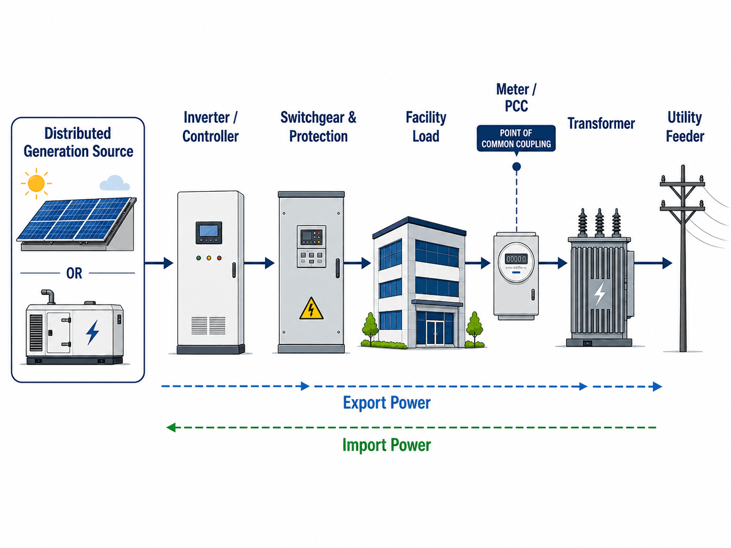
The most important idea is the bidirectional relationship at the point of common coupling: the facility can import power from the grid, export excess local generation, or reduce grid demand when local production serves the load directly.
What is a Distributed Generation System?
A distributed generation system is a power generation system located near the point of use or connected to a local distribution network. Instead of producing all electricity at large centralized plants and transmitting it long distances, distributed generation places smaller resources closer to homes, buildings, campuses, industrial facilities, rural loads, or distribution feeders.
Common examples include rooftop solar PV, commercial solar arrays, small wind turbines, combined heat and power units, fuel cells, backup generators, and hybrid systems that combine generation with battery storage. In practical power systems work, the term is less about the fuel source and more about where the source connects and how it interacts with local loads and the distribution grid.
Distributed generation is not automatically off-grid. Many DG systems remain grid-connected and depend on utility interconnection equipment, metering, protection, and control settings to operate safely.
Distributed Generation vs Centralized Generation
Centralized generation relies on large power plants that send electricity through transmission and distribution networks to many customers. Distributed generation places smaller sources closer to the load or within the distribution system. The tradeoff is that DG can reduce local demand and improve flexibility, but it also makes distribution planning more complex.
| Comparison point | Centralized generation | Distributed generation |
|---|---|---|
| Typical location | Large power plant connected through the transmission system. | Near a building, campus, industrial load, community site, or distribution feeder. |
| Power flow pattern | Historically one-way from plant to transmission to distribution to load. | Can create local serving, reduced import, limited export, or reverse power flow. |
| Planning focus | Generation dispatch, transmission capacity, fuel supply, and system-wide reliability. | PCC behavior, feeder voltage, transformer loading, protection, metering, and local controls. |
| Operational visibility | Usually monitored and dispatched by utilities or grid operators. | May require additional monitoring, smart inverter settings, DER management, or utility coordination. |
| Engineering challenge | Large-scale dispatch and grid stability. | Many smaller systems interacting with feeders that were not always designed for two-way flow. |
Distributed Generation vs DER, Microgrids, and Stand-Alone Systems
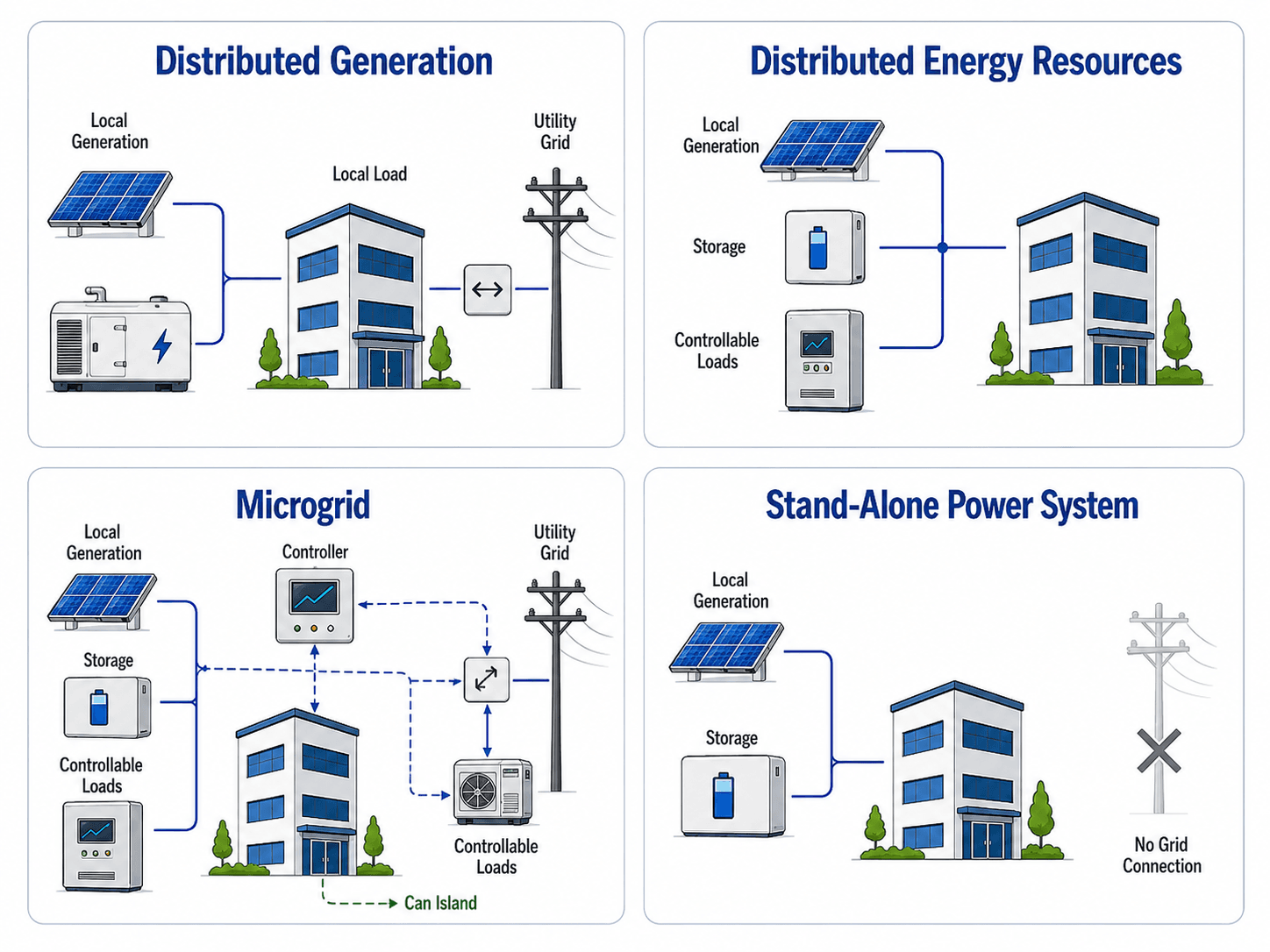
Distributed generation is often grouped with related terms, but those terms are not identical. A rooftop solar array can be distributed generation. A battery, controllable load, or EV charger may be a distributed energy resource. A microgrid is a more complete local system with controls and islanding capability. A stand-alone system operates without a utility grid connection.
| Term | What it means | Key distinction |
|---|---|---|
| Distributed generation | Local power generation connected near a load or within the distribution system. | The focus is on generation location and electrical connection. |
| Distributed energy resources | A broader category that can include generation, storage, flexible loads, EV charging, and control devices. | DER is broader than generation alone. |
| Microgrid | A defined local electrical system with generation, loads, controls, and the ability to operate connected to or separated from the grid. | Intentional islanding and control are central features. |
| Stand-alone power system | An independent power system serving loads without a utility grid connection. | The system must meet the load without relying on grid import. |
How Distributed Generation Works in a Power System
A distributed generation system begins with a local source, such as solar PV, a generator, CHP equipment, or a fuel cell. That source is connected through power conversion equipment, protection, metering, and sometimes storage or controls. The system may serve nearby loads first, export surplus generation, or import from the grid when the local source cannot meet demand.
Point of common coupling
The point of common coupling, or PCC, is the electrical interface where the distributed generation system connects to the facility or utility system. It is a major review point because voltage, power quality, export behavior, utility metering, anti-islanding protection, and interconnection settings are often evaluated at or near this location.
Import and export behavior
A facility with distributed generation can still draw power from the grid during high load, low solar output, generator downtime, or battery depletion. It may export power when local generation exceeds local load and export is allowed. Non-export systems use controls or protective functions to keep net export near zero.
Inverter-based generation
Solar PV and many battery systems connect through inverters. Inverters control voltage, frequency response, reactive power behavior, ride-through settings, and disconnection logic. That makes inverter settings central to modern distributed generation design, especially when many systems are connected to the same feeder.
Distributed Generation Operating Modes and Export Control
One of the most important early design decisions is how the DG system is allowed to operate at the grid interface. A system that only offsets local load is reviewed differently from a system that exports power, and a backup-only generator is reviewed differently from a microgrid-capable system.
| Operating mode | What it means | Typical use | Main engineering issue |
|---|---|---|---|
| Non-export DG | Controls prevent the system from exporting power past the PCC. | Facilities that want local energy offset without feeder export. | Controls and protection must reliably prevent backfeed under fast load changes. |
| Limited-export DG | Export is allowed but capped at a defined value. | Solar-plus-storage projects or constrained feeder connections. | Metering, controller response, and utility-approved export limits become critical. |
| Full-export DG | Excess generation can flow to the utility feeder when local production exceeds load. | Community solar, commercial PV, and local generation projects designed to export. | Feeder hosting capacity, voltage rise, protection coordination, and transformer loading must be checked. |
| Backup-only DG | Generation serves loads during an outage or transfer condition rather than continuous grid-parallel operation. | Emergency generators and standby power systems. | Transfer sequence, grounding, load priority, and separation from the utility source must be correct. |
| Islandable DG or microgrid mode | The system can intentionally separate from the grid and serve a defined local load boundary. | Campuses, critical facilities, remote communities, and resilience projects. | Controls, protection, black-start logic, load shedding, and resynchronization require detailed design. |
Export control is not just a software setting. It affects metering, utility screens, protection requirements, equipment ratings, commissioning tests, and the operating agreement for the system.
Main Components of Distributed Generation Systems
A complete distributed generation installation is more than a generator or solar array. The balance-of-system equipment determines whether the installation can operate safely, coordinate with the utility, protect equipment, and deliver useful power to the load.
| Component | Role in the system | Engineering implication |
|---|---|---|
| Generation source | Produces electrical power from solar, wind, fuel, heat recovery, or another local energy source. | Source type controls dispatchability, emissions, variability, maintenance, and operating cost. |
| Inverter or generator controls | Converts and controls electrical output so it can serve loads or connect to the grid. | Settings affect voltage support, ride-through behavior, power factor, and trip response. |
| Switchgear and protection | Provides switching, fault interruption, isolation, and safety functions. | Protection must coordinate with utility devices, facility equipment, and generator behavior. |
| Metering and PCC equipment | Measures import, export, production, or net energy at the interconnection point. | Metering determines billing, operating visibility, and interconnection compliance. |
| Transformer | Matches voltage levels between generation, facility distribution, and the utility feeder. | Transformer rating, grounding, impedance, and connection type influence loading and fault behavior. |
| Battery storage | Stores energy and can support peak shaving, backup operation, or controlled export. | Storage changes the time profile of DG output and can reduce or increase feeder stress depending on controls. |
| Communications and monitoring | Provides data for operators, utility coordination, alarms, or automated dispatch. | Visibility becomes more important as DG penetration increases across a feeder. |
Common Types of Distributed Generation
Distributed generation can be renewable, fuel-based, dispatchable, intermittent, or hybrid. The electrical behavior of the system depends less on the marketing label and more on whether the source is controllable, inverter-based, export-limited, storage-supported, or designed for backup operation.
| DG type | Typical use | Power systems consideration |
|---|---|---|
| Rooftop or ground-mounted solar PV | Offset building load, reduce daytime energy purchases, and support clean energy targets. | Output varies with sunlight and can create midday export or feeder voltage rise at high penetration. |
| Battery-supported solar | Shift solar energy, reduce peaks, provide backup power, or smooth export. | Control strategy matters as much as battery size; poor dispatch can worsen feeder loading. |
| Combined heat and power | Serve facilities with steady electric and thermal loads, such as hospitals or industrial plants. | Can be dispatchable and efficient when thermal energy is used productively. |
| Fuel cells | Provide relatively steady local generation for buildings, campuses, and critical facilities. | Often suited for continuous operation but still needs interconnection and protection review. |
| Diesel or natural gas generators | Backup power, emergency power, peak shaving, or temporary local supply. | Fault contribution, emissions, fuel logistics, transfer equipment, and operating limits must be reviewed. |
| Small wind or renewable hybrid systems | Rural, remote, coastal, agricultural, or site-specific renewable applications. | Production profile depends heavily on local resource quality and storage or grid support. |
Benefits and Limitations of Distributed Generation Systems
Distributed generation can improve a power system, but the benefits are not automatic. A DG project is useful when the generation profile, load profile, interconnection design, controls, and feeder conditions support the intended objective.
| Potential benefit | Why it helps | Limitation engineers must check |
|---|---|---|
| Reduced local grid demand | Generation near the load can reduce the amount of power imported from the feeder. | Demand reduction only occurs when DG output aligns with the facility load profile. |
| Lower electrical losses | Serving power close to the load can reduce some distribution and transmission losses. | Loss reduction is not guaranteed if excess generation causes reverse flow or poor feeder utilization. |
| Improved resilience | Local generation can support critical loads during outages when designed for backup or islanded operation. | Grid-connected DG normally disconnects during outages unless islanding controls and transfer equipment are included. |
| Renewable energy integration | Rooftop and local solar projects can add clean generation near customers. | Solar variability can create voltage, ramping, and export challenges at high penetration. |
| Peak demand management | DG and storage can reduce facility peak demand when dispatched correctly. | Controls must match the tariff, load shape, demand interval, and battery operating limits. |
| Infrastructure deferral | Local generation may reduce loading on constrained equipment during critical periods. | This only works if DG output is available when the feeder, transformer, or substation is constrained. |
Grid Impacts of High Distributed Generation Penetration
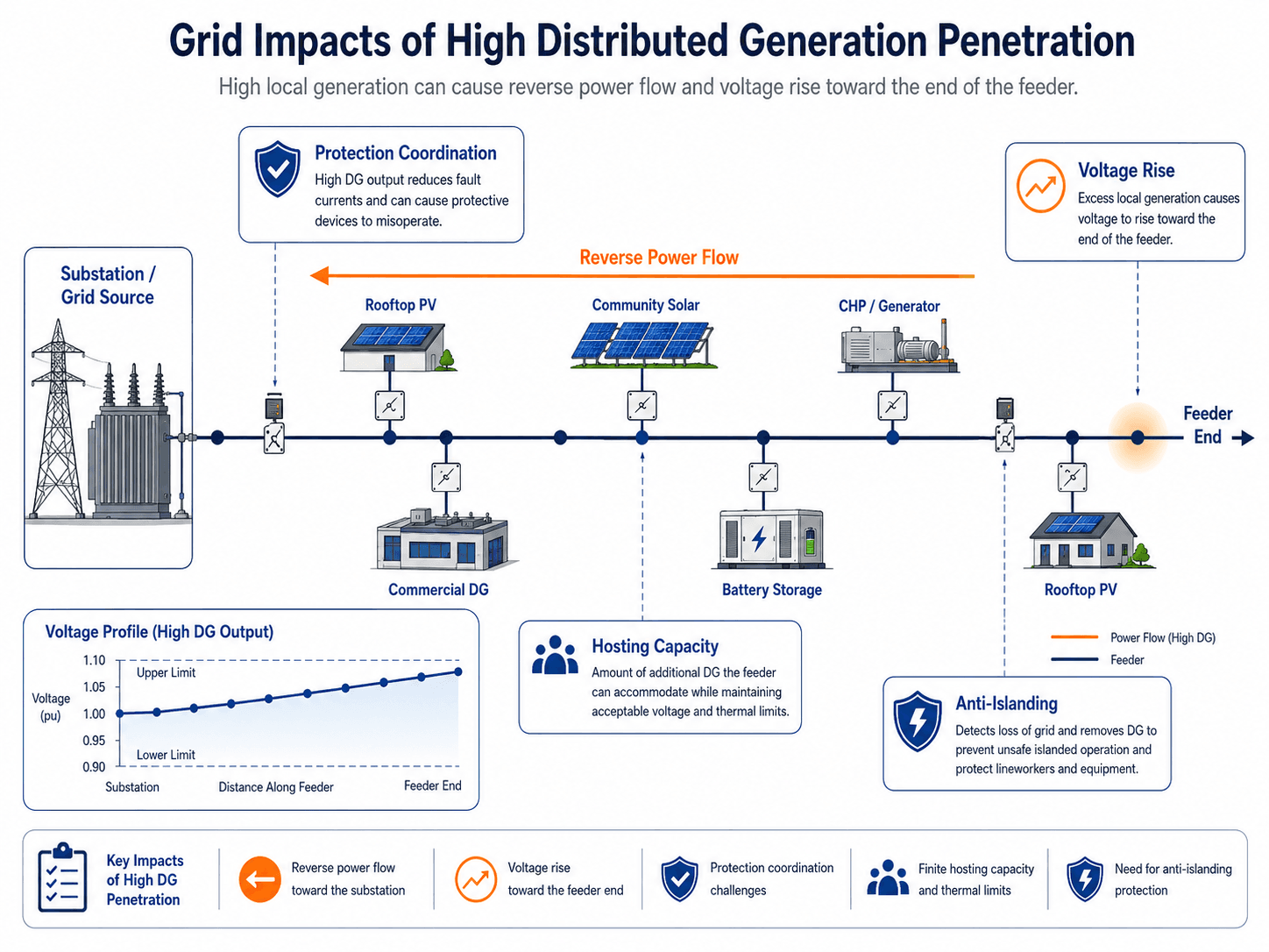
A small generator connected to a strong feeder may have little visible system impact. Many generators connected to the same feeder can change the way the distribution system behaves. The most common concerns are reverse power flow, voltage rise, protection coordination, hosting capacity, and islanding risk.
Reverse power flow
Traditional distribution feeders were usually planned for power to flow from the substation toward customers. When local generation exceeds local load, power can flow in the opposite direction. This may affect voltage regulators, transformer loading, feeder automation, protection coordination, and utility operating procedures.
Voltage rise
Distributed generation can raise local voltage, especially at the end of long or lightly loaded feeders. A solar-heavy feeder may stay within limits most of the year but approach voltage constraints during high generation and low load conditions.
Protection and islanding
Distributed generation changes available fault current and can make protective device coordination more difficult. Anti-islanding functions are required so local generation does not unintentionally energize a section of grid that utility crews expect to be de-energized.
Power quality and inverter behavior
DG can also affect harmonics, flicker, voltage fluctuation, and reactive power behavior. Modern inverters may help support voltage and frequency, but only when their settings, grid code requirements, and utility operating practices are aligned.
What Controls Distributed Generation Performance?
The usefulness of a distributed generation system depends on more than its nameplate capacity. Engineers evaluate how the system behaves across time, loading conditions, feeder conditions, outage scenarios, and utility operating limits.
| Control factor | Why it matters | Engineering implication |
|---|---|---|
| Minimum daytime load | Low local demand during high generation increases the chance of export. | Export limits, storage dispatch, or inverter controls may be needed. |
| Feeder impedance and length | Weak or long feeders are more sensitive to voltage rise and fluctuation. | Voltage studies and hosting capacity checks become more important. |
| Transformer rating and connection | Transformers may see reverse loading, thermal limits, or grounding-related impacts. | Equipment ratings and grounding configuration must match the interconnection design. |
| Inverter ride-through settings | Modern inverters may remain connected through certain voltage and frequency events. | Settings must align with utility requirements and system stability expectations. |
| Storage control strategy | A battery can reduce peaks or increase export depending on dispatch logic. | Control objectives should be defined before sizing or interconnection review. |
| Protection coordination | DG can change fault current direction and magnitude. | Relays, fuses, breakers, reclosers, and inverter trip behavior need coordinated review. |
How Engineers Evaluate DG Interconnection
Distributed generation interconnection is both a technical review and an operating agreement. The goal is to confirm that the system can connect without creating unacceptable voltage, protection, power quality, safety, or operational problems for the facility or the utility feeder.
Define the operating mode → identify the PCC → compare generation output to load → check feeder hosting capacity → review voltage and power quality → evaluate protection and anti-islanding → confirm metering and communications → complete commissioning and witness testing.
| Review step | What engineers check | Why it matters |
|---|---|---|
| Operating mode | Non-export, limited export, full export, backup-only, or islandable operation. | The operating mode determines the study scope, controls, and protection requirements. |
| PCC and service voltage | Exact electrical interface, meter location, service voltage, transformer connection, and ownership boundary. | The PCC is where voltage, export, power quality, and utility requirements are usually evaluated. |
| Generation and load profile | Hourly generation, minimum load, peak load, seasonal variation, and expected export. | Annual energy estimates do not reveal high-generation/low-load edge cases. |
| Hosting capacity | Feeder voltage, thermal ratings, nearby DG, regulator behavior, and operating configuration. | The feeder may limit DG size even when the facility service equipment appears adequate. |
| Protection coordination | Relays, fuses, breakers, reclosers, inverter fault current, transfer equipment, and trip settings. | Fault detection and isolation must still work with generation connected in different operating states. |
| Commissioning | Meter verification, anti-islanding tests, shutdown function, settings confirmation, and utility witness requirements. | Commissioning proves that the installed system matches the reviewed design and operating assumptions. |
Distributed Generation Design Review Checklist
A distributed generation review should test whether the system can operate safely under normal operation, abnormal grid conditions, high-generation/low-load periods, and outage scenarios. The checklist below is not a replacement for a utility study, but it shows the practical questions engineers usually need to answer before a DG installation is considered mature.
Start with the load profile and generation profile, define the intended operating mode, identify the PCC, check export behavior, review feeder and transformer constraints, verify protection and anti-islanding functions, then confirm that metering, controls, commissioning, and maintenance responsibilities are clear.
| Review check | What to look for | Why it matters |
|---|---|---|
| Operating objective | Energy offset, peak shaving, backup power, export revenue, resilience, or microgrid operation. | The objective changes equipment selection, controls, interconnection requirements, and economics. |
| Generation-to-load relationship | Compare DG output against minimum, average, and peak facility load. | High output during low load can create export, voltage rise, or curtailment needs. |
| Point of common coupling | Confirm the exact electrical interface used for utility review and metering. | Power quality, voltage, export, and protection requirements often reference the PCC. |
| Export mode | Full export, limited export, non-export, or backup-only operation. | Export behavior strongly affects feeder studies, metering, relay settings, and utility approval. |
| Feeder hosting capacity | Review nearby DG, voltage limits, thermal limits, regulator behavior, and feeder configuration. | A project that looks acceptable at the facility may still be constrained by the local distribution feeder. |
| Protection and anti-islanding | Verify breaker, fuse, relay, inverter, transfer, and disconnection behavior. | Protection must keep workers, equipment, and customers safe during faults and grid outages. |
| Storage and controls | Confirm charge/discharge limits, backup reserve, export schedules, and controller priorities. | Storage can solve or create grid problems depending on how it is dispatched. |
| Commissioning and O&M | Check test procedures, shutdown access, labeling, maintenance intervals, and monitoring alarms. | Good design still fails if field crews cannot operate, isolate, test, or maintain the system safely. |
Example: Commercial Facility With Solar, Storage, and Grid Connection
Consider a commercial facility with rooftop solar, a battery storage system, and a normal utility service connection. During the middle of the day, solar production may serve building loads directly. If production exceeds the building load and export is allowed, power may flow through the PCC toward the utility feeder.
Normal operation
During typical business hours, the system may reduce utility demand by serving part of the facility load locally. If the battery is programmed for peak shaving, it may discharge during high-demand periods and charge during low-cost or high-solar periods.
Low-load, high-solar operation
On a mild weekend with low building load and strong solar output, the system may produce more than the facility consumes. This is where export limits, voltage rise, inverter settings, and utility rules become important.
Outage operation
Unless the system is specifically designed with islanding controls, transfer equipment, protection, and a defined load boundary, it should disconnect during a utility outage. A grid-connected DG system does not automatically provide backup power.
Distributed Generation in Smart Grids, DERMS, and Virtual Power Plants
As more distributed generation connects to feeders, utilities and operators need better visibility and control. Smart grid systems, distributed energy resource management systems, and virtual power plant concepts help coordinate many smaller resources so they behave more like an organized grid asset instead of isolated installations.
This does not remove the need for local engineering review. It adds another layer of control: communication, telemetry, dispatch signals, aggregation rules, customer participation, and utility operating constraints must work together with the physical interconnection.
At low penetration, DG is often reviewed one project at a time. At high penetration, the feeder becomes a coordinated operating environment where visibility, hosting capacity, inverter settings, and dispatch rules become system-level concerns.
Engineering Judgment and Field Reality
In real projects, distributed generation design often comes down to site-specific constraints. A system that is technically simple at one building may require detailed studies at another because of feeder length, existing DG penetration, transformer limits, utility protection philosophy, or the facility’s minimum load profile.
The nameplate rating is not the whole story. A 500 kW DG system serving a steady 1 MW industrial load behaves very differently from the same 500 kW system connected near the end of a lightly loaded rural feeder.
Experienced engineers also separate energy value from reliability value. Solar PV may reduce annual energy purchases, but it does not provide firm backup unless the project includes storage, controls, transfer equipment, and a tested operating sequence for outage conditions.
When This Breaks Down
Simplified distributed generation diagrams are useful for learning, but they can hide the conditions that control real performance. The concept breaks down when readers assume every local generator improves reliability, reduces costs, lowers emissions, and helps the grid without checking operating context.
- A solar-only system may not support critical loads during an outage unless it is designed for islanded operation.
- High DG penetration can raise feeder voltage during low-load periods even when each individual project seems reasonable.
- Backup generators can improve resilience but may introduce fuel logistics, emissions constraints, maintenance needs, and fault-current concerns.
- Battery storage can reduce peak demand or worsen feeder export depending on dispatch settings.
- Protection devices may not coordinate correctly if DG changes fault current magnitude, direction, or duration.
Common Mistakes and Practical Checks
Distributed generation is easy to describe but easy to oversimplify. The most common mistakes come from treating all local generation as interchangeable or assuming that a clean energy source automatically behaves well on every distribution feeder.
- Calling any DG system a microgrid even when it has no islanding controller, defined boundary, or backup sequence.
- Using annual energy production to judge a project without checking hourly load, minimum demand, and export conditions.
- Ignoring the PCC and assuming the utility sees the same behavior that the facility sees internally.
- Assuming inverter settings are generic instead of project-specific and utility-reviewed.
- Forgetting that storage is a control problem as much as a sizing problem.
Do not assume behind-the-meter means invisible to the grid. If the system can export, alter voltage, change fault behavior, or remain energized during abnormal conditions, the distribution system still has to account for it.
Standards, Interconnection, and Design References
Distributed generation becomes a power systems engineering issue when it connects to a utility feeder, facility service, or shared electrical system. Interconnection requirements help define how generation should respond to abnormal voltage and frequency, how it should disconnect or ride through events, and how it should communicate or coordinate with the electric power system.
- IEEE 1547: IEEE 1547 interconnection and interoperability requirements for distributed energy resources provide a widely recognized technical basis for DER interconnection with electric power systems.
- Utility interconnection rules: Local utility procedures, screens, studies, export limits, metering requirements, commissioning tests, and witness requirements often control how a specific project is reviewed.
- Engineering use: Engineers use these references alongside load data, equipment ratings, protection studies, inverter settings, feeder models, and field commissioning records to evaluate whether a DG project can connect safely.
Frequently Asked Questions
A distributed generation system is a smaller power generation resource located close to the load or connected at the distribution level rather than only at a large central power plant. Common examples include rooftop solar, small generators, CHP units, fuel cells, and battery-supported hybrid systems.
No. Distributed generation means local generation near a load or distribution feeder. A microgrid is a controllable local electrical system that usually includes generation, loads, controls, and the ability to operate connected to or separated from the main grid.
Distributed generation can provide backup power only if the system is designed for that operating mode. A grid-connected solar or generator system normally needs transfer equipment, protection, controls, storage or dispatchable generation, and a defined load boundary before it can safely support loads during a utility outage.
Reverse power flow occurs when local distributed generation produces more power than the nearby load consumes, causing power to flow back toward the utility feeder or substation. It can affect voltage regulation, protection coordination, transformer loading, metering, and utility operating practices.
Distributed generation can create reverse power flow, voltage rise, protection coordination issues, power quality concerns, transformer loading changes, and islanding risks. These issues depend on feeder strength, system size, export limits, inverter settings, protection design, and local utility requirements.
The point of common coupling is where the distributed generation system electrically interfaces with the utility or facility system. It matters because voltage, power quality, export behavior, protection settings, metering, and interconnection requirements are often evaluated at or near this point.
Summary and Next Steps
Distributed generation systems place local power sources near the loads they serve or within the distribution network. They can reduce grid demand, support resilience, integrate renewable energy, and improve local energy flexibility when designed correctly.
The engineering challenge is that distributed generation also changes power flow, voltage behavior, protection coordination, metering, interconnection requirements, and utility operating practices. A strong review looks beyond nameplate capacity and checks load profile, export mode, PCC location, feeder limits, inverter settings, storage controls, commissioning, and field maintainability.
Where to go next
Continue your learning path with related Turn2Engineering power systems resources.
-
Load Flow Analysis
Learn how engineers study voltage, power transfer, loading, and operating conditions across electrical networks.
-
Stand-Alone Power Systems
Compare grid-connected distributed generation with off-grid systems that must serve loads independently.
-
Smart Grids
Explore how sensors, communications, automation, and controls help manage DERs across modern power systems.