Key Takeaways
- Core idea: A load bearing wall supports vertical loads from floors, roofs, beams, or walls above and transfers those loads toward the foundation.
- Engineering use: Engineers evaluate load bearing walls by tracing the load path, checking tributary area, and verifying studs, headers, beams, posts, connections, and foundation support.
- What controls it: Joist direction, wall alignment, roof framing, openings, span length, material capacity, and the support below usually control whether a wall is structural.
- Practical check: Wall location and joist direction are clues, not proof; a wall should not be removed until the load path and replacement support are confirmed.
Table of Contents
Introduction
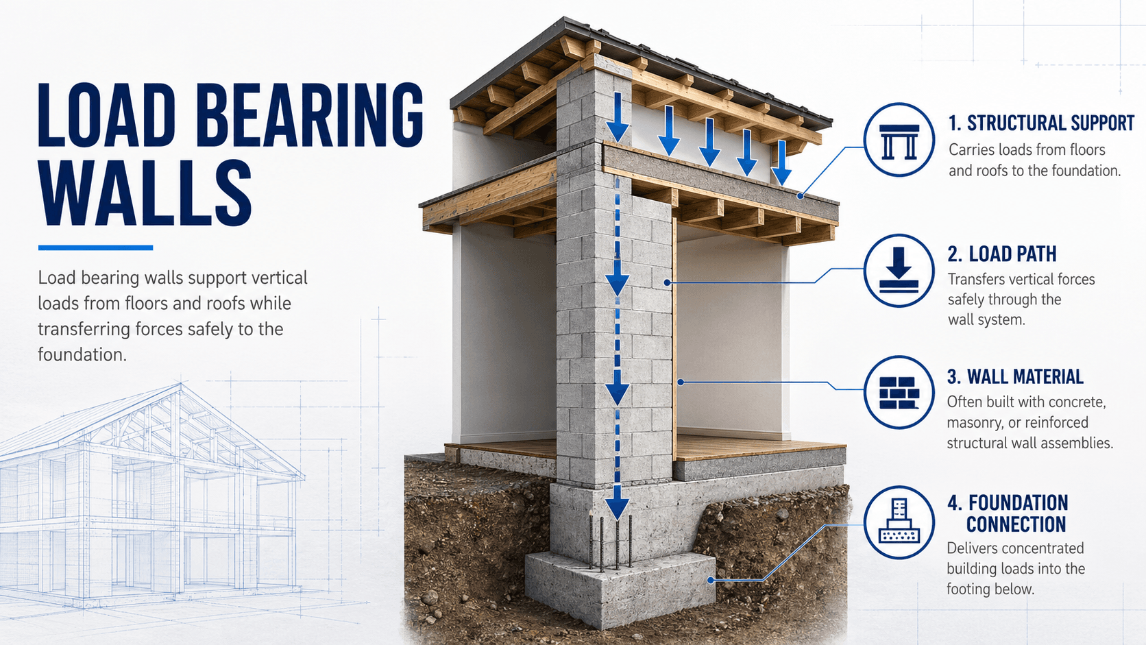
Load bearing walls are structural walls that support vertical loads in addition to their own weight and transfer those loads down through the building to the foundation. They matter because removing, cutting, or weakening one without a replacement beam, header, post, or foundation support can interrupt the load path and cause cracking, sagging, or structural failure.
How Load Bearing Walls Transfer Loads
Notice that the wall is not judged by appearance alone. The important question is where the load comes from, how it enters the wall, and what structural element carries it next.
What Is a Load Bearing Wall?
A load bearing wall is a wall that supports more than its own weight. In a typical building, it may carry floor joists, roof rafters, trusses, beams, headers, masonry above, or another wall stacked on a higher floor. The wall then transfers those loads through studs, masonry units, concrete, or other vertical elements to the structure below.
The key engineering concept is load path analysis. A wall is structural when it forms part of the path that carries gravity or lateral forces to the foundation. A wall can be thin and still load bearing, thick and still nonbearing, or both load bearing and lateral-force-resisting depending on how the building is framed.
How Load Bearing Walls Work
Load bearing walls work by collecting load from framing above and delivering it to a stable support below. For gravity loads, the wall acts like a vertical compression element. For lateral loads, some bearing walls may also act as braced walls or shear walls if they include sheathing, masonry, reinforced concrete, hold-downs, anchors, or other lateral-force-resisting details.
Gravity load path
In a wood-framed floor, joists may bear directly on an interior wall. In that case, floor dead load, live load, and sometimes partition load are delivered into the top plate, then through studs, bottom plate, floor framing, beams, footings, and soil. If that wall is removed, the load still exists; it must be redirected through another structural system.
Openings and headers
Doors, windows, and large room openings interrupt the vertical studs that normally carry load. A header or beam is used to bridge the opening and transfer load to jack studs, posts, or supporting masonry at each side. The larger the opening and the greater the load above, the more important header sizing, bearing length, and support below become.
Vertical support below the wall
A wall that carries load must have a credible support path below it. That support might be another wall, a beam, a girder, a foundation wall, a continuous footing, isolated footings, or a slab designed for the load. A replacement beam that bears on weak framing or an unsupported slab can simply move the problem to a different location.
How to Tell If a Wall Is Load Bearing
The best way to identify a load bearing wall is to trace the load path using plans, attic framing, basement framing, crawlspace conditions, and visible beams or supports. Simple rules can help, but they should be treated as clues rather than final proof.
- Check structural drawings: Framing plans, foundation plans, and beam schedules are more useful than architectural room layouts.
- Look at joist direction: Walls perpendicular to joists are more likely to support them, while walls parallel to joists may still carry point loads, roof loads, or bracing loads.
- Check the basement or crawlspace: Beams, posts, foundation walls, or continuous footings below a wall are strong clues that the wall carries load.
- Look for stacked walls: Walls aligned vertically through multiple floors often form a continuous gravity load path.
- Inspect roof framing: Rafters, trusses, purlins, struts, or ceiling joists may deliver loads to interior walls.
- Treat exterior walls carefully: Exterior walls commonly support roof, floor, wind, and bracing loads.
If you cannot draw a continuous arrow from the load above the wall to a beam, wall, footing, or foundation below it, the wall needs closer review before it is altered.
Load Bearing Wall vs Partition Wall vs Shear Wall
Not every wall performs the same structural job. Some walls mainly divide space, some carry vertical load, some resist wind or seismic forces, and some do more than one of those jobs at the same time.
| Wall type | Main purpose | Typical engineering concern |
|---|---|---|
| Load bearing wall | Supports vertical loads from floors, roofs, beams, or walls above. | Compression capacity, load path, headers, bearing length, support below, and foundation demand. |
| Partition wall | Divides rooms and usually supports only its own weight and finishes. | Attachment, deflection compatibility, sound separation, fire rating, and finishes. |
| Shear wall or braced wall | Resists lateral loads from wind or earthquakes. | Sheathing, anchors, hold-downs, chord forces, collectors, openings, and overturning. |
| Masonry bearing wall | Uses brick, block, stone, or reinforced masonry to carry gravity load. | Compression, slenderness, eccentricity, reinforcement, mortar condition, and lateral stability. |
| Curtain wall | Provides enclosure while gravity load is carried by the main frame. | Wind load transfer, anchors, movement joints, water control, and deflection compatibility. |
What Controls Whether a Wall Is Structural?
A wall becomes structurally important because of the load it receives and the support it provides, not because of a single visual clue. Engineers look at framing direction, supported area, material capacity, openings, and whether the load continues safely into the foundation.
| Factor | Why it matters | Engineering implication |
|---|---|---|
| Tributary area | The wall may support a portion of floor, roof, snow, or attic load. | Larger tributary area increases wall line load, header demand, beam size, and foundation reaction. |
| Joist or truss bearing | Framing members may deliver load directly into the wall. | Removing the wall usually requires a beam or other transfer element. |
| Openings in the wall | Openings interrupt vertical load-carrying studs or masonry. | Headers, jack studs, posts, lintels, and bearing lengths must be checked. |
| Support below | Loads must continue into framing, walls, beams, footings, or foundations below. | A new beam may require posts, pads, footings, or foundation strengthening. |
| Lateral bracing role | A wall may resist wind or seismic loads even if it is not heavily loaded vertically. | Removal can reduce stiffness, overturning resistance, or braced wall length. |
| Material and condition | Wood, steel, masonry, and concrete walls fail differently. | Stud crushing, buckling, masonry cracking, corrosion, settlement, and moisture damage change capacity. |
Basic Load Estimate for a Bearing Wall
Engineers often start with a simplified line load estimate before moving into detailed member checks. The idea is to convert the supported floor or roof area into a load per foot of wall. This does not replace design, but it explains why longer spans, wider tributary widths, snow load, and heavier construction quickly increase demand.
In this simplified expression, \(w\) is the approximate line load on the wall, usually in pounds per linear foot or kilonewtons per meter. The terms \(q_D\), \(q_L\), and \(q_R\) represent dead, live, and roof-related area loads, while \(b_D\), \(b_L\), and \(b_R\) represent the tributary widths that deliver those loads to the wall.
- w Wall line load, commonly expressed in plf or kN/m.
- q Area load from dead, live, roof, snow, or attic loading, commonly expressed in psf or kPa.
- b Tributary width of framing that delivers load to the wall.
The next checks usually include stud capacity, header or beam design, bearing stress, deflection, connection detailing, and the support below. For deeper background on applied forces, see Structural Loads.
Load Bearing Wall Identification Checklist
Use this checklist as a practical screening tool. It helps organize observations before engineering review, but it should not be used as permission to remove or cut a wall.
Start above the wall and trace load downward: roof or floor framing → joists, trusses, beams, or rafters → wall, header, or post → lower framing or foundation → soil. If the path stops, jumps, or relies on an unknown element, the wall should be treated as structural until verified.
| Check or decision | What to look for | Why it matters |
|---|---|---|
| Plans and framing drawings | Beam tags, bearing wall notes, joist direction, truss layout, foundation walls, or footing lines. | Drawings provide the most direct evidence of intended load path. |
| Framing direction | Joists, rafters, or trusses bearing on or crossing over the wall. | Members that bear on the wall usually deliver gravity load into it. |
| Support below | Beam, girder, post, crawlspace pier, foundation wall, thickened slab, or continuous footing below the wall. | A structural wall typically needs a credible load path beneath it. |
| Stacked walls | Walls located directly above or below on multiple levels. | Stacked walls often transfer vertical load floor by floor. |
| Openings and headers | Double or built-up headers, jack studs, posts, lintels, or beams over doors and openings. | Heavier headers may indicate load is being transferred around an opening. |
| Lateral resistance | Sheathing panels, hold-downs, anchor bolts, braced wall lines, or reinforced masonry. | The wall may be important even if vertical gravity load appears modest. |
Can a Load Bearing Wall Be Removed?
A load bearing wall can often be removed, but the wall’s structural job must be replaced. That usually means adding a beam or header to span the opening, posts or built-up studs to support the beam ends, connections to transfer load, and adequate support below the posts.
Typical removal sequence
A proper removal workflow usually starts with determining what the wall carries, estimating tributary loads, checking whether the wall is part of a lateral bracing system, selecting a beam or header, verifying end bearing, and checking the support below. Temporary shoring is commonly installed before the existing wall is cut or removed.
What the replacement beam actually does
The replacement beam collects the loads that used to flow through many studs along the wall and concentrates them at fewer support points. That is why posts, bearing plates, connectors, and foundation support matter just as much as the beam itself.
Replacing a wall with a strong beam is not enough if the beam ends bear on framing that cannot carry the concentrated reactions.
Engineering Judgment and Field Reality
Real buildings are not always framed exactly as shown in simplified diagrams. Remodels, undocumented additions, cut joists, old masonry, sagging beams, concealed utilities, fire damage, water damage, and previous wall removals can all change the actual load path. Engineers therefore combine drawings with field observations before deciding whether a wall is bearing or nonbearing.
Older buildings require special care because framing may not follow modern assumptions. A wall that looked secondary during original construction may have become important after later alterations. Likewise, a wall may support a short point load from a beam, roof strut, or column even if most of the wall length is not heavily loaded.
The riskiest wall removals are often not the obvious exterior bearing walls; they are interior walls that quietly support a roof valley, stair opening, beam end, stacked wall, or interrupted joist system.
When This Breaks Down
Simplified load bearing wall rules break down when the framing is irregular, the building has been modified, or the wall also participates in lateral resistance. In those cases, a simple visual inspection may miss the actual structural function of the wall.
- Parallel joists do not guarantee nonbearing: The wall may still carry roof framing, a beam end, ceiling load, bracing, or a point load.
- Wall thickness is not reliable by itself: A thin stud wall can be load bearing, and a thick finish wall can be nonstructural.
- Openings can change behavior: Large openings concentrate load into headers, posts, and local bearing points.
- Slabs are not always adequate footings: A post reaction from a new beam may exceed what an ordinary slab-on-grade was intended to support.
- Lateral systems can be hidden: Sheathing, hold-downs, anchors, or masonry reinforcement may make a wall important for wind or seismic resistance.
Common Mistakes and Practical Checks
Most load bearing wall mistakes come from treating one clue as a final answer. A safe evaluation looks at the full system: loads above, framing layout, wall condition, openings, support below, and the lateral-force-resisting role of the wall.
- Assuming a wall is nonbearing because it sounds hollow: Wood stud bearing walls are often hollow behind drywall.
- Ignoring the foundation: New posts may need footings or verified support below, not just a beam above.
- Forgetting about roof loads: Interior walls may carry roof struts, ceiling joists, or loads from complex roof geometry.
- Removing bracing: A wall may resist wind or seismic loads even if gravity loading appears small.
- Oversizing the opening without checking deflection: Strength is not the only issue; excessive sag can crack finishes and affect doors, windows, and floors.
The most common mistake is designing the beam but not checking the complete load path through the posts, floor framing, foundation, and soil below.
Relevant Codes, Manuals, and Design References
Load bearing wall decisions are project-specific, but several common references help engineers classify loads, evaluate framing, and design replacement support systems.
- International Residential Code and local building codes: Commonly used for residential wall framing, headers, wall bracing, foundations, and prescriptive construction requirements.
- International Building Code: Used for broader building classifications, structural design requirements, occupancy conditions, and code-level load combinations.
- ASCE 7: Provides minimum design loads for buildings, including dead, live, roof, snow, wind, and seismic loading used to evaluate bearing systems.
- National Design Specification for Wood Construction: Used for wood member design, including studs, beams, columns, bearing, and connection behavior.
- TMS 402/602 masonry standards: Used when load bearing walls are built with structural masonry rather than light-frame construction.
Frequently Asked Questions
Common clues include walls that align with beams or foundation walls below, walls perpendicular to floor joists, stacked walls above and below, exterior walls, and walls supporting roof framing. These are clues, not proof. The reliable method is to trace the load path from roof or floor framing down to the foundation.
A load bearing wall can often be removed, but the load must be replaced by an engineered beam, header, posts, connections, and adequate support below. The replacement system must carry the same gravity and sometimes lateral loads without creating excessive deflection, overstressed members, or foundation problems.
Exterior walls are usually treated as load bearing because they often support roof, floor, wall, wind, and bracing loads. Some exterior cladding systems are non-load-bearing curtain walls, but in typical wood, masonry, and light-frame residential construction, exterior walls should be assumed structural until verified otherwise.
A load bearing wall primarily carries vertical gravity loads from floors, roofs, or walls above. A shear wall primarily resists lateral loads from wind or earthquakes. Some walls do both, which is why wall removal can affect not only vertical support but also the building’s lateral bracing system.
Summary and Next Steps
Load bearing walls are structural elements that carry roof, floor, wall, beam, or lateral system loads and transfer those forces through a continuous path to the foundation. The important issue is not whether a wall “looks structural,” but whether loads depend on it.
A strong evaluation traces the load path, checks framing direction, identifies support below, reviews openings, considers lateral bracing, and verifies that any replacement beam or header has adequate end support. The most reliable wall decisions combine drawings, field inspection, engineering judgment, and project-specific design checks.
Where to go next
Continue your learning path with related Turn2Engineering resources.
-
Load Bearing Structures
Learn how walls, beams, columns, slabs, and foundations work together as a complete load-carrying system.
-
Load Path Analysis
Deepen the most important concept behind wall evaluation: tracing where forces go next.
-
Structural Inspections
See how field observations, distress signs, and framing conditions are translated into engineering decisions.